
Related Manuals for Fiilex Q6 COLOR


Summary of Contents for Fiilex Q6 COLOR
- Page 1 USER MANUAL USER MANUAL Model No:FLXQ6CLR English Version 175W LED Fresnel Light Rev.01 - 08/14/2024...
- Page 2 firmware updates. Q6 Webpage The Fiilex Logo, Fiilex names, and all other trademarks in this document pertaining to Fiilex services or Fiilex products are trademarks of DiCon FiberOptics, Inc., its affiliates, and subsidiaries. Fiilex is a registered trademark. All rights reserved. DiCon FiberOptics 1689 Regatta Blvd. Richmond, CA 94804 USA.
-
Page 3: Table Of Contents
INDEX INTRODUCTION ................................... INDEX......................................03 SAFETY INFORMATION..............................05 WARRANTY..................................... PACKAGING..................................09 PACKAGE CONTENTS OPTIONAL ACCESSORIES SPECIFICATIONS................................09 3 - TECHNICAL DRAWING INFORMATION.........................10 4 - PHOTOMETRIC DATA..............................5 - BEAM PROFILE................................. INSTALLATION..................................12 MOUNTING 8 - START UP..................................... CONNECT AND DISCONNECT POWER 9 - PRODUCT OVERVIEW..............................14 PARTS DIAGRAM 10 - CONTROL PANEL................................ - Page 4 14 - RDM FUNCTIONS................................. 15 - ACCESSORIES ADJUSTMENTS..........................ADDITIONAL ACCESSORIES 16 - MAINTENANCE................................MAINTENANCE AND CLEANING VISUAL CHECK OF PRODUCT HOUSING 17 - TROUBLESHOOTING..............................57 18 - ERROR CODES LIST……………………………………………………………………………………………………………………..58...
-
Page 5: Safety Information
• Do not reapply power until repairs have been completed. • Refer any service operation not described in this manual to the Fiilex Customer Service team. Installation • Make sure that all visible parts of the product are in good condition before its use or installation. - Page 6 • Warning! Disconnect the fixture from AC power and allow it to cool for at least 10 minutes before handling. • Only technicians who are authorized by Fiilex or Authorized service partners are permitted to open the fixture. • Users may carry out external cleaning, following the warnings and instructions provided, but any service operation not described in this manual must be referred to a qualified service technician.
- Page 7 SAFETY INFORMATION Disposal • This product is supplied in compliance with European Directive 2012/19/EU – Waste Electrical and Electronic Equipment (WEEE). To preserve the environment please dispose/ recycle this product at the end of its life according to the local regulation. The products to which this manual refers comply with •...
-
Page 8: Warranty
Unless otherwise stated, your product is covered by a one-year parts and labor limited warranty. Fiilex guarantees, to the original buyer, that this product is to be free of defects in both workmanship and material for a period of one year from the date of shipment. This warranty extends to all products which have proved defective through normal use but excludes products that have been disassembled, modified, or misused by the buyer or any other person. -
Page 9: Packaging
•1x Q6 COLOR w/ LumenRadio •1x FLXQ6CLR-PSU-185V •1x FLXQ6CLR-PSU-ACJ6-TRUE1 •1x FLXQ6CLR-BD8 Optional accessories The most updated accessories list, descriptions, and information about the product can be found on the Fiilex webpage at www.fiilex.com 2 - SPECIFICATION Field Angle 19° / 36°/ 50° lens tube... -
Page 10: Technical Drawing Information
3 - TECHNICAL DRAWING INFORMATION FLXQ6CLR - Weight Fixture: 8.4lbs / 3.8kg (With yoke, barndoors) Power adapter: 3.2lbs / 1.5kg 4 - PHOTOMETRIC DATA... -
Page 11: Beam Profile
5 - BEAM PROFILE Beam Profile of Q6 COLOR... -
Page 12: Installation
Warning! When clamping the fixture to a truss or other structure at any angle, use clamps of half coupler type. Do not use any type of clamp that does not completely encircle the structure when fastened. Attach Clamp *Fiilex does not include a clamp with lighting products. -
Page 13: Start Up
7 - CONNECTION TO AC POWER Warning! The max power consumption is 175W. To protect from electric shock, the fixture must be grounded. The product is equipped with auto-switching power supply that automatically adjusts to any 50-60Hz AC power source from 100-240 Volts. -
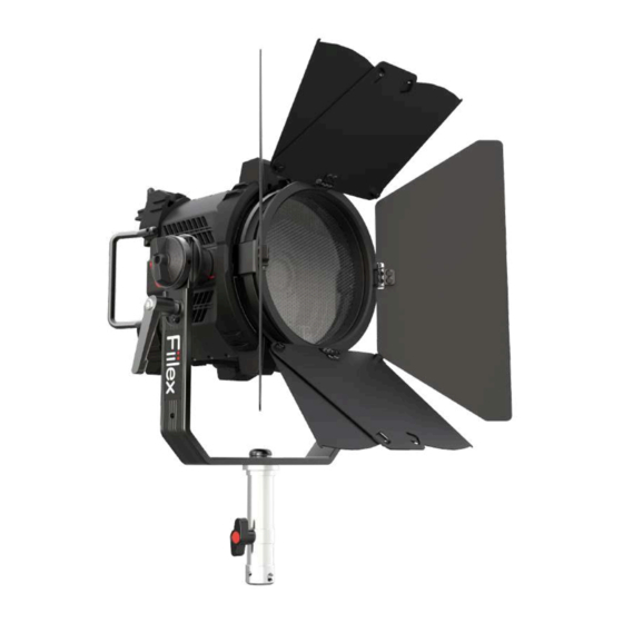
Page 14: Product Overview
9 - PRODUCT OVERVIEW Parts diagram 1. Handles 10. Fresnel Lens 19. DMX Input (XLR-Male 5-pin) 2. Fresnel Zoom 11. Fresnel Lens Holder 20. Antenna 3. Tilt Lock Lever 12. Dual Locking V-Mount 21. Navigation Pad 4. Yoke (1/4"-20 UNC Screw Hole) 13. -
Page 15: Control Panel
10 - CONTROL PANEL The product has a display and buttons to access the control panel functions. Display and buttons layout 1. OLED Panel : Used to view all menu functions 2. Knobs : Adjustments (Parameter adjusted depends on DMX operating mode) 3. -
Page 16: Knob Function
10 - CONTROL PANEL Knob Function Knob Turn Press Turn Press Turn Press Press Press CCT/HUE Quick GN/SAT Quick Up/Down Left/Right Confirm Actions Adjust Adjust Adjust Adjust Adjust Move Move Knob behavior for all modes 11 - DMX CONNECTION... -
Page 17: Connection Of The Dmx Signal
11 - DMX CONNECTION Connection of the DMX signal The product has XLR-5 sockets for DMX input and output. The default pin-out on both sockets is shown below: Instructions for a reliable DMX connection Use a shielded twisted-pair cable designed for RS-485 devices: standard microphone cables cannot transmit control data reliably over long runs. -
Page 18: Dmx Termination
11 - DMX CONNECTION DMX termination The termination is prepared by soldering a 120 Ohm 1/4 W resistor between pins 2 and 3 of the male XLR-5 connector, as shown in figure. X control circuit is not isolated. • Cumulative leakage current on the DMX control circuit is less than 3.5 mA. DMX addressing In order to start controlling the product via DMX, the first step is to select a DMX address, also known as the start channel. -
Page 19: Menu Structure
12 - MENU STRUCTURE Menu * Double click center button to return to the upper level. * Enter the current mode function of the Dashboard by pressing the center button. * Please refer to the Dashboard section for detailed flow of each function. - Page 20 12 - MENU STRUCTURE Menu * Double click center button to return to the upper level. * Enter the current mode function of the Dashboard by pressing the center button. * Please refer to the Dashboard section for detailed flow of each function.
-
Page 21: Dmx Mapping
13 - DMX MAPPING The product can communicate using RDM (Remote Device Management) protocol over a DMX512 Network. RDM is a bi-directional communications protocol for use in DMX512 control systems. RDM is the open standard for DMX512 device configuration and status monitoring. RDM protocol allows data packets to be inserted into a DMX512 data stream without affecting existing non-RDM equipment. -
Page 22: Dmx Modes
13 - DMX MAPPING DMX Modes Standard Modes Mode 8-bit ( DMX Footprint ) 16-bit ( DMX Footprint ) Page Mode 1 ( 6 ) Mode 9 ( 10 ) HSI* Mode 2 ( 6 ) Mode 10 ( 10 ) RGBW * Mode 3 ( 8 ) - Page 23 13 - DMX MAPPING DMX Modes ALL Modes Mode 8-bit ( DMX Footprint ) 16-bit ( DMX Footprint ) Page ALL MODES Mode 76 ( 12 ) Mode 77 ( 20 )
- Page 24 13 - DMX MAPPING Mode 1 (8-bit) / Mode 9 (16-bit) : CCT 8-bit 16-bit Function 8-bit/16-bit Value Range Master Intensity 0 – 255 0 – 65, 535 0% – 100% 0 – 255 0 – 65, 535 2000K – 10000K 0 –...
- Page 25 13 - DMX MAPPING Mode 2 (8-bit) / Mode 10 (16-bit) : HSI 8-bit 16-bit Function 8-bit/16-bit Value Range Master Intensity 0 – 255 0 – 65, 535 0% – 100% 0 – 255 0 – 65, 535 0° – 360° Saturation 0 –...
- Page 26 13 - DMX MAPPING Mode 3 (8-bit) / Mode 11 (16-bit) : RGBW 8-bit 16-bit Function 8-bit/16-bit Value Range Master Intensity 0 – 255 0 – 65, 535 0% – 100% Intensity Red 0 – 255 0 – 65, 535 0% –...
- Page 27 13 - DMX MAPPING Mode 4 (8-bit) / Mode 12 (16-bit) : CCTHSI 8-bit 16-bit Function 8-bit/16-bit Value Range Master Intensity 0 – 255 0 – 65, 535 0% – 100% 0 – 255 0 – 65, 535 2000K – 10000K 0 –...
- Page 28 13 - DMX MAPPING Mode 5 (8-bit) / Mode 13 (16-bit) : CCTRGBW 8-bit 16-bit Function 8-bit/16-bit Value Range Master Intensity 0 – 255 0 – 65, 535 0% – 100% 0 – 255 0 – 65, 535 2000K – 10000K 0 –...
- Page 29 13 - DMX MAPPING Mode 6 (8-bit) / Mode 14 (16-bit) : CIExy 8-bit 16-bit Function 8-bit/16-bit Value Range Master Intensity 0 – 255 0 – 65, 535 0% – 100% 0 – 255 0 – 65, 535 0.0 – 0.8 0 –...
- Page 30 13 - DMX MAPPING Mode 7 (8-bit) / Mode 15 (16-bit) : GEL 8-bit 16-bit Function 8-bit/16-bit Value Range Master Intensity 0 – 255 0 – 65, 535 0% – 100% 0 – 9 None 10 – 19 Bastard Amber 20 –...
- Page 31 13 - DMX MAPPING Mode 40 (8-bit) / Mode 45 (16-bit) : RGB 8-bit 16-bit Function 8-bit/16-bit Value Range Intensity Red 0 – 255 0 – 65, 535 0% – 100% Intensity Green 0 – 255 0 – 65, 535 0% –...
- Page 32 13 - DMX MAPPING Mode 41 (8-bit) / Mode 46 (16-bit) : CCTxy 8-bit 16-bit Function 8-bit/16-bit Value Range Master Intensity 0 – 255 0 – 65, 535 0% – 100% 0 – 255 0 – 65, 535 2000K – 10000K 0 –...
- Page 33 13 - DMX MAPPING Mode 42 (8-bit) / Mode 47 (16-bit) : ICTHS 8-bit 16-bit Function 8-bit/16-bit Value Range Master Intensity 0 – 255 0 – 65, 535 0% – 100% 0 – 255 0 – 65, 535 2000K – 10000K 0 –...
- Page 34 13 - DMX MAPPING Mode 43 (8-bit) / Mode 48 (16-bit) : ICTRGBW 8-bit 16-bit Function 8-bit/16-bit Value Range Master Intensity 0 – 255 0 – 65, 535 0% – 100% 0 – 255 0 – 65, 535 2000K – 10000K 0 –...
- Page 35 13 - DMX MAPPING Mode 44 (8-bit) / Mode 49 (16-bit) : ICTxy 8-bit 16-bit Function 8-bit/16-bit Value Range Master Intensity 0 – 255 0 – 65, 535 0% – 100% 0 – 255 0 – 65, 535 2000K – 10000K 0 –...
- Page 36 13 - DMX MAPPING Mode 50 (8-bit) / Mode 63 (16-bit) : EZ CCT 8-bit 16-bit Function 8-bit/16-bit Value Range Master Intensity 0 – 255 0 – 65, 535 0% – 100% 0 – 255 0 – 65, 535 2000K – 10000K 0 –...
- Page 37 13 - DMX MAPPING Mode 53 (8-bit) / Mode 66 (16-bit) : EZ CCTHSI 8-bit 16-bit Function 8-bit/16-bit Value Range Master Intensity 0 – 255 0 – 65, 535 0% – 100% 0 – 255 0 – 65, 535 2000K – 10000K 0 –...
- Page 38 13 - DMX MAPPING Mode 55 (8-bit) / Mode 68 (16-bit) : EZ CIExy 8-bit 16-bit Function 8-bit/16-bit Value Range Master Intensity 0 – 255 0 – 65, 535 0% – 100% 0 – 255 0 – 65, 535 0.0 – 0.8 0 –...
- Page 39 13 - DMX MAPPING Mode 58 (8-bit) / Mode 71 (16-bit) : EZ ICTHS 8-bit 16-bit Function 8-bit/16-bit Value Range Master Intensity 0 – 255 0 – 65, 535 0% – 100% 0 – 255 0 – 65, 535 2000K – 10000K 0 –...
- Page 40 13 - DMX MAPPING Mode 60 (8-bit) / Mode 73 (16-bit) : EZ ICTxy 8-bit 16-bit Function 8-bit/16-bit Value Range Master Intensity 0 – 255 0 – 65, 535 0% – 100% 0 – 255 0 – 65, 535 2000K – 10000K 0 –...
- Page 41 13 - DMX MAPPING Mode 76 (8-bit) / Mode 77 (16-bit) : ALL MODES 8-bit 16-bit Function 8-bit/16-bit Value Range Master Intensity 0 – 255 0 – 65, 535 0% – 100% 0 – 9 10 – 19 20 – 29 RGBW 30 –...
- Page 42 13 - DMX MAPPING 8-bit 16-bit Function 8-bit/16-bit Value Range Function 8-bit/16-bit Value Range 0 – 255 0 – 65, 535 2000K – 10000K 0 – 255 0 – 65, 535 0° – 360° Neutral (0) 0 – 9 0 – 9 Green Full magenta ~ Full Saturation 0 –...
- Page 43 13 - DMX MAPPING DEMO 8-bit 16-bit Function 8-bit/16-bit Value Range Function 8-bit/16-bit Value Range 0 – 9 None 10 – 19 Bastard Amber 0 – 9 No effect(Stop Effect) 20 – 29 Straw 10 – 19 Candle 30 – 39 Light Amber 20 –...
- Page 44 13 - DMX MAPPING CIExy 8-bit 16-bit Function 8-bit/16-bit Value Range 0 – 255 0 – 65, 535 0.0 – 0.8 0 – 255 0 – 65, 535 0.0 – 0.8...
- Page 45 13 - DMX MAPPING Candle Fireworks Television 16-bi 8-bit 8-bit/16-bit 8-bit/16-bit 8-bit/16-bit Function Range Function Range Function Range Value Value Value 0 – 9 Action 0 – 9 Warmer 0 – 9 Color 10 – 19 Horror Color 10 – 19 Neutral Color 10 –...
- Page 46 13 - DMX MAPPING Color Chase Paparazzi Strobe 0 – 9 Warmer Saturati 0 – 255/ 0 – 255 / 0% -100% Color 10 – 19 Neutral 0 – 360º 0 – 65,535 0 – 65,535 20 – 29 Cooler 0 –...
-
Page 47: Rdm Functions
14 - RDM FUNCTIONS Table of Contents Page RDM Identification DMX Personality Identification Network Management Status Collection RDM Information Product Information DMX512 Setup Dimmer Settings RDM E1.37 version (not supported yet) Power/Lamp Settings Control Manufacturer Command... -
Page 48: Rdm Identification
QUAD COLOR FLXQ8CLRLR Q8 COLOR-LR FLXMOTOQUADCLR MOTOQUAD 6124 FLXG3CLR G3 COLOR FLXQ3CLRLR Q3 COLOR-LR FLXRPU FLXMOTOK40 MOTOK40 FLXQ6CLR Q6 COLOR FLXG6CLR G6 COLOR FLXMOTOQ3 MOTOQ3 FLXK10CLR K10 COLOR UID Example 6 1 2 4 0 1 0 0 0 2... - Page 49 14 - RDM FUNCTIONS Personality Description Description [Decimal Data: Mode Description (Footprint)] P3/Q5/Q8/Q10/Q3/ G3/G9/Q6/G6 0x01 1: CCT 8-bit (Footprint 6 ) 0x02 2: HSI 8-bit (Footprint 6 ) 0x03 3: RGBW 8-bit (Footprint 8 ) 0x04 4: CCTHSI 8-bit (Footprint 9 ) 0x05 5: CCTRGBW 8-bit (Footprint 11 ) 0x06...
- Page 50 14 - RDM FUNCTIONS 0x020 57: EZ CCTxy 8-bit (Footprint 6 ) 0x021 58: EZ ICTHS 8-bit (Footprint 5 ) 0x022 59: EZ ICTRGBW 8-bit (Footprint 7 ) 0x023 60: EZ ICTxy 8-bit (Footprint 5 ) 0x024 61: EZ 3200K 8-bit (Footprint 1 ) 0x025 62: EZ 5600K 8-bit (Footprint 1 ) 0x026...
-
Page 51: Network Management
14 - RDM FUNCTIONS Network Management Command Description DISC UNIQUE BRANCH 0x0001 Devices respond to discovery messages. DISC MUTE 0x0002 Mute the device. DISC UNMUTE 0x0003 Unmute the device. Status Collection (For Art-Net) Command Description The QUEUED_MESSAGE parameter shall be used to retrieve a message from the QUEUED MESSAGE 0x0020 responder‘s message queue. -
Page 52: Product Information
14 - RDM FUNCTIONS Product Information Command Description This parameter is used to retrieve a variety of information about the device that is DEVICE INFO 0x0060 normally required by a controller This parameter provides a text description of up to 32 characters for the device DEVICE MODEL DESCRIPTION 0x0080 model type. -
Page 53: Power/Lamp Settings
GET/SET WHITE POINT 0x8001 Range 2000 ~ 10000 Kelvin Applies to HSI, RGBW and RGB modes GET/SET FIILEX_FAN 0x8002 0:Silent, 1:Auto, 2:Full speed, 3:OFF FIILEX_ERROR 0x8003 GET Fiilex error code Format: (X, Y) FIILEX_CIEXY 0x8004 Range: X: 0~0.8 Y: 0~0.8... -
Page 54: Accessories Adjustments
15 - ACCESSORIES ADJUSTMENTS Press the pin (1) and the snap will automatically open upwards (2). Slide(3) barndoor down to barndoor holder. NOTE: To remove the accessory, reverse the procedure. Additional accessories... -
Page 55: Maintenance
» Electrical, photometric and functional checks; eventual repairs. Warning! The use of alcohol or any other detergent could damage the lenses. • All other service operations on the product must be carried out by Fiilex, its approved service agents or trained and qualified personnel. -
Page 56: Visual Check Of Product Housing
16 - MAINTENANCE Visual check of product housing • The parts of the product cover/housing should be checked for signs of damage at least every two months. In addition, the front lens holder should be checked mechanically to ensure if it is firmly fastened to the fixture. -
Page 57: Troubleshooting
• Check that power is switched ON and cables are plugged in. • Internal fault. • Contact the Fiilex Service or authorized service partner. Do not remove parts and/or covers, or carry out any repairs or service that are not described in this Safety and User Manual unless you have both authorization from Fiilex and the service documentation. -
Page 58: Error Codes List
• Reboot Fixture Error • Contact fiilex@fiilex.com • Error code number indicates which component caused error. • Reboot Fixture Provide this to Fiilex Customer Driver Board • Dry fixture thoroughly (8+ hours) if 11-18 Service if unable to resolve Disconnect subject to rain or high humidity •... - Page 59 18 - ERROR CODES LIST Troubleshooting Error Code Description Notes Steps •Ensure power inputs are supplying the correct voltage. 70-74 System Boot Up Error •Reboot Fixture. •Contact fiilex@fiilex.com •Ensure power inputs are supplying the correct voltage Insufficient Voltage •Use a new power source to main input (Main Circuit) •Replace power cable •Reboot fixture...
Need help?
Do you have a question about the Q6 COLOR and is the answer not in the manual?
Questions and answers