Table of Contents
Advertisement
Unauthorized reproduction or copying of all or part of this operating manual is prohibited.
If you have damaged or misplaced the operating manual and require a new copy, contact your nearest
Oriental Motor office.
The operating manual is subject to change without prior notice for the purpose of improvement or change
in product specifications, or to improve the manual itself.
The utmost care has been taken to ensure that all information contained in the operating manual is cor-
rect. However, please contact your nearest Oriental Motor office should you find any unclear descrip-
tions, errors or omissions.
is a trademark of Oriental Motor Co., Ltd., registered in Japan and other countries.
Windows is a registered trademark of Microsoft Corp.
Other products and companies referred to in this manual are the trademarks or registered trademarks
of the respective companies. All references to other manufacturer's products made in this manual are
intended strictly for reference purposes and do not constitute a requirement or recommendation re-
garding the use thereof. Oriental Motor Co., Ltd. shall in no way be liable for the performance or com-
patibility of other manufacturers' products.
© Copyright ORIENTAL MOTOR CO., LTD. 2001
Please contact your nearest ORIENTAL MOTOR office for further information.
ORIENTAL MOTOR U.S.A. CORP.
Technical Support Line Tel:(800)468-3982
Available from 8:30 AM to 5:00 PM, P.S.T.
ORIENTAL MOTOR (EUROPA) GmbH
Headquarters and Düsseldorf Office
Tel:0211-5206700
Fax:0211-52067099
Munich Office
Tel:08131-59880
Fax:08131-598888
Hamburg Office
Tel:040-76910443
Fax:040-76910445
ORIENTAL MOTOR (UK) LTD.
Tel:01252-519809
Fax:01252-547086
ORIENTAL MOTOR (FRANCE) SARL
Tel:01 47 86 97 50
Fax:01 47 82 45 16
ORIENTAL MOTOR ITALIA s.r.l.
Tel:02-3390541
Fax:02-33910033
TAIWAN ORIENTAL MOTOR CO., LTD.
Tel:(02)8228-0707
Fax:(02)8228-0708
SINGAPORE ORIENTAL MOTOR PTE LTD.
Tel:(745)7344
Fax:(745)9405
ORIENTAL MOTOR (MALAYSIA) SDN BHD
Tel:(03)79545778
Fax:(03)79541528
INA OM LTD. (KOREA)
Tel:(032)822-2042~3 Fax:(032)819-8745
ORIENTAL MOTOR CO., LTD.
Headquarters
Tokyo, Japan
Tel:(03)3835-0684
Fax:(03)3835-1890
Printed on Recycled Paper
5-Phase Stepping Driver with Built-in Oscillator
TD
Series
V
Type
(potentiometer type)
OPERATING MANUAL
Thank you for purchasing an Oriental Motor product.
This operating manual describes product handling
procedures and safety precautions.
Please read it thoroughly to ensure safe operation.
Always keep the manual where it is readily available.
HP-0021
Table of Contents
Introduction ................................. 2
Safety precautions ........................ 3
Precautions for use ..................... 5
Preparation ................................. 6
Checking the product .................. 6
Applicable motors ..................... 6
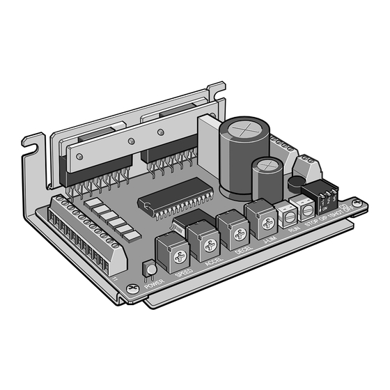
Names and functions of parts ...... 7
Installation ................................. 8
Location for installation ............... 8
Installation method ..................... 8
Connection ................................. 9
Power connection ..................... 9
Motor connection........................ 9
I/O Connection ........................10
Connection of I/O .....................11
Explanation of I/O .....................12
Timing chart ...........................14
Setting .......................................15
acceleration / deceleration rates ...15
Switch settings ........................16
Setting of motor currents ............17
Overvoltage protection function ......19
Inspection .................................20
Troubleshooting and
corrective actions ........................20
Specifications ...........................22
Dimensional drawing ..................23
Advertisement
Table of Contents

Related Manuals for Oriental motor VEXTA TD Series


Summary of Contents for Oriental motor VEXTA TD Series
-
Page 1: Table Of Contents
All references to other manufacturer’s products made in this manual are intended strictly for reference purposes and do not constitute a requirement or recommendation re- garding the use thereof. Oriental Motor Co., Ltd. shall in no way be liable for the performance or com- patibility of other manufacturers’ products. -
Page 2: Introduction
ø3.5(0.14 DIA.)-2 Holes component for general industrial equipment. Do not use the prod- uct for any other purpose. Oriental Motor shall not be liable what- soever for any damage arising from failure to observe this warning. This product is a compact, lightweight bipolar constant-current dri-... -
Page 3: Safety Precautions
Safety precautions The precautions provided in this section are intended to ensure safe Specifications and correct use of the product, thereby preventing damage or injury to the user or other personnel. Fully understand the meaning of each TD514-V TD528-V Model item before using the product. - Page 4 Turn off the power to the driver in case of a power failure. Failure Operation Symptom Possible cause Corrective action to do so may result in injury or equipment damage when the mo- The motor Either the START input or RUN input is Confirm that both signal input to ON tor starts suddenly upon power recovery.
-
Page 5: Precautions For Use
TD Series unit. The driver uses semiconduc- Should an abnormality be noted, discontinue any use and contact tor elements, so exercise your nearest Oriental Motor office. due caution when handling Keep the driver’s heat-sink temperature the driver. The driver may at 80°C (176°F) or below during use... -
Page 6: Preparation
When the driver’s protection function is activated, remove the Setting of motor currents …………17 Overvoltage protection function ……19 Inspection ……………………………20 Troubleshooting and Thank you for purchasing an Oriental Motor product. This operating manual describes product handling corrective actions ……………………20 procedures and safety precautions. Specifications ………………………22 Please read it thoroughly to ensure safe operation. -
Page 7: Names And Functions Of Parts
The minimum settable motor current varies depending on the con- This section covers the names and functions of the driver’s respec- Names and nected motor and power-source voltage. Shown below are repre- tive parts. functions of parts sentative values when the driver is combined with each of the ap- See the reference page indicated for details on each part. -
Page 8: Installation
Installation This section covers the driver’s installation location and method. The motor operating current is set to 1.4 A/phase ( TD514-V ) or 2.8 Setting of motor TD528-V A/phase ( ) at the factory. If the rated current of the con- currents nected motor is other than these values, be sure to use the motor The driver is designed and manufactured for use as an internal com-... -
Page 9: Connection
Connection Setting the acceleration / deceleration rates This section covers the methods of connecting the driver, motor, power and controller, as well as the connection examples and inputs /outputs. Acceleration rate and deceleration rate can be set independently us- ing the potentiometer. Turning the potentiometer clockwise increases Connect the power source, motor and I/Os to the driver’s corre- the acceleration/deceleration rate. -
Page 10: I/O Connection
Setting A connection example is given in the figure below. In addition to the driver’s internal potentiometer, an external poten- I/O connection Setting of operating tiometer or external DC voltage may also be used to set the motor’s speeds and operating speed. -
Page 11: Connection Of I/O
Connection of I /O cables Timing chart Connection of I /O Connect the I/O cables to the driver. Use shielded wire for the cables. Oscillator mode, Level input (SW 1-1 off, SW 1-2 off ) NOTE Table of I / O functions in oscillator mode The following two modes are Pin no. -
Page 12: Explanation Of I/O
Input signals Explanation of I/O EXTVR input All input signals to the driver are photocoupler inputs. All input signals are invalid in oscillator mode (communication). External VR / built-in VR selection Signal status indicates the ON (current supplied) or OFF (current not When this input is OFF, built-in potentiometer is selected and the supplied) status of the internal photocoupler rather than the voltage speed is set via the built-in potentiometer becomes effective.
Need help?
Do you have a question about the VEXTA TD Series and is the answer not in the manual?
Questions and answers