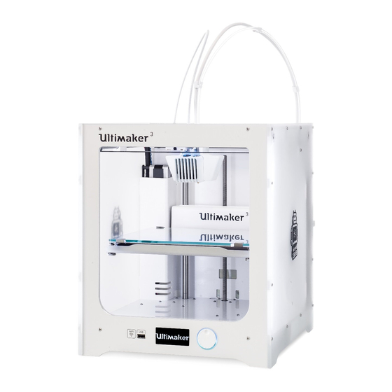
Ultimaker 3 Repair Manual
Hide thumbs
Also See for 3:
- User manual ,
- Original manual (60 pages) ,
- Installation and user manual (50 pages)
Advertisement
Quick Links
Repair manual Ultimaker 3
Replacing
the Ultimainboard
For internal use only
Replacing the Ultimainboard
Important: First make sure you are working ESD safe. The
Ultimainboard is very vulnerable to ESD events. There is a high chance
that the Olimex will be damaged if this repair is not done in an ESD
safe way.
Important: Make sure the filament is removed, the Ultimaker is
turned off and the power supply is disconnected before you start the
replacement.
Tip: All orientations are noted as seen from the front of the printer
Note: These instructions are the same for the Ultimaker 3 and
Ultimaker 3 Extended.
Equipment/supplies needed
Tools
•
ESD mat
•
ESD bracelet
•
2.0 hex screwdriver
•
Ball head screwdriver
Parts
•
1x 1548 - Ultimainboard
1
Page.
Advertisement

Summary of Contents for Ultimaker 3
- Page 1 Tip: All orientations are noted as seen from the front of the printer Note: These instructions are the same for the Ultimaker 3 and Ultimaker 3 Extended. Equipment/supplies needed Tools •...
- Page 2 • Manually lift the Z stage all the way up. all the way down. • Gently place the Ultimaker 3 on its left side. • Grab the motor cover at the top. • Pull it forwards and then to the left to detach it from the panels.
- Page 3 Disassembly 5. Remove the Ultimainboard from the bottom panel 6. Remove all connections from the Ultimainboard • Remove the four M3x20 bolts that secure the Ultimainboard to Tip: The bolt in the back right corner under the ferrite core can be hard •...
- Page 4 Disassembly • Remove the right feeder motor • Remove the single flatwire • Remove the print head cable • Remove the left feeder motor • Heated bed heater wires • Remove the Z motor • When the Ultimainboard is completely loose, lastly take the •...
- Page 5 Note: If the thermal conductive pad does not stick anymore, please replace the pad. Do not glue the thermal conductive pad to the Ultimainboard. 3. Align the Ultimainboard with the bolts 4. Attach the Ultimainboard to the bottom panel 5. Reconnect all cables to the Ultimainboard •...
- Page 6 Re-assembly • Connect the single flatwire to the ten pins at the opposite side of • There are three motor wires coming from the left side of the • The middle one is the Z motor, you can see it coming from the the mainboard.
- Page 7 Re-assembly • Connect the white heated bed sensor to ‘HEATED BED’. • Connect the LED cable to the connector on the middle of the board. • Put the print head cable into the connector at the end of the • Connect the filament detection cable coming from the right board.
- Page 8 Slide the cover over the Ultimainboard, making sure that no • Secure the Ultimainboard cover to the bottom panel with the two • Turn the Ultimaker 3 upright again. cables are stuck between the cover and the frame. M3x12 bolts. •...


Need help?
Do you have a question about the 3 and is the answer not in the manual?
Questions and answers