Advertisement
Advertisement
Table of Contents

Related Manuals for Triplett PCAL200


Summary of Contents for Triplett PCAL200
- Page 1 User Manual PCAL200 Voltage and Current (mA) Source Calibrator...
-
Page 2: Safety Information
4 Safety Information User should use the calibrator in accordance with the instructions of the manual, or the protective devices provided for the calibrator may be damaged. The Company is not responsible for any damage caused by failure to follow the safety warning information provided. “... - Page 3 the insulation around the connector. • Select the proper function and range according to the measurement requirements. • Make sure that the battery door is securely closed before using the calibrator. • Remove the test lead from the calibrator before opening the battery door. •...
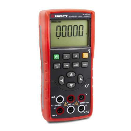
- Page 4 Figure 1. Overall Diagram Figure 2. Output Terminals...
-
Page 5: Output Terminals
5.1 Output terminals 5.2 Buttons Figure 2 shows the input and output terminals of the calibrator. Figure 3 shows the calibrator buttons. Table 3 explains their Table 2 explains their purposes. functions 2. Output terminals Terminal Function description mA-: DCI output (-) terminal SIMULATE output (+) terminal mA+: DCI output (+) terminal SIMULATE output (-) terminal... - Page 6 Figure 3. Button Functions Button name Description Power button Power on/off V button Press this button to switch the function to voltage output Output waveform Select output waveform of current output automatic waveform switch button Output START button Start/stop button for automatic waveform output in the output current function 5, 7 Output setting button Increase/decrease output setting position...
-
Page 7: Display Screen
5.3 Display screen a: Output status mark b: Main display area for output data c: Automatic sawtooth wave mode output current mark d: Output data polarity indicator e: Auto-stepping mode output current mark f: Automatic triangular wave mode output current mark g: Output current automatic waveform operation mark h: Output setting position indicator i: Output current percentage data polarity indicator... - Page 8 6 Preparations ◼ Operating precautions Safe use for the calibrator ⚫ When using the calibrator for the first time, be sure to read the safety information listed in Section IV. ⚫ Do not open the instrument housing. To inspect or repair the instrument’s internal components, please contact the seller from whom you purchased the product. ⚫...
- Page 9 ⚫ Use the instrument in a flat and horizontal area ◼ Do not use the instrument in the following environment ⚫ Places directly exposed to sunlight or close to heat sources ⚫ Places close to mechanical vibrations ⚫ Approaching to any interference source, such as high-voltage equipment or engine power ⚫...
- Page 10 WARNING ⚫ To avoid electric shock, the test lead must be removed from the calibrator before opening the battery door. The battery door must be closed tightly before using the calibrator. Caution ⚫ To prevent the risk of liquid leakage or battery explosion, install the positive and negative poles of the battery correctly. ⚫...
- Page 11 Step 1: Before replacing the battery, remove the test lead and turn off the calibrator. Step 2: Use a slotted screwdriver to rotate the battery door screw by a quarter turn counterclockwise and remove the battery door. Step 3: Correctly install 3 pieces of AA LR6 alkaline batteries into the battery compartment in the direction as it indicates. Step 4: After replacing the battery, close the battery door tightly again.
- Page 12 7 Use of output mode The calibrator should be used for outputting a DC signal. WARNING To avoid electric shock, it is not allowed to apply voltage exceeding the rated voltage indicated on the calibrator between the terminals or between any terminal and ground of the calibrator. The calibrator should be used in situations where the voltage to ground at any terminal does not exceed a peak value of 30V.
- Page 13 Step 1: Press 〔V〕 button to switch to the voltage output function and the character ‘V’ on the display screen will light up. At this time, the DC voltage output function will take into force. Step 2: Use output setting button to set the output value. ...
- Page 14 screen shows the parameters to be set; ⚫ Set the required span by pressing the〔〕/〔〕key Parameter '0' means: When pressing the 〔〕/〔〕key, the corresponding value of the setting bit increases/decreases by 1; Parameter '25' means: When pressing the〔〕/〔〕key, the output value increases/decreases by 25% of the measuring range;...
- Page 15 7.2.1 Automatic stepping output mode of output current Step 1: Press 〔 〕 button in the output current function state to switch to the stepping mode function of DC current. At this time, the symbol on the display screen will light up. Step 2: Press 〔CONFIG〕...
- Page 16 period (5-200S) and press 〔ZERO〕 button to save the settings. Press 〔CONFIG〕 button again to exit the settings interface. Step 3: Press 〔START〕 button to initiate the automatic stepping of output current and the logo 〔RUN〕 on the display screen will light up at this time.
- Page 17 7.3 Output DC current (passive) Step 1: Connect the lead to the target device ⚫ Connect the black lead to the SIMULATE - end and the red lead to the SIMULATE + end. ⚫ Connect the other end of the two leads to the input end of the controlled device and ensure that the terminal polarity is correct.
-
Page 18: Factory Settings
8. Factory settings The calibrator can be used for changing the default factory settings. To enter: Press and hold the Backlight button, and then press the Power button to turn on the instrument. After the instrument enters the settings interface, release the Backlight button. 8.1 Automatic shutdown time setting Step 1: After entering the settings interface, you will find “APOF”... -
Page 19: Factory Default Setting
8.3 Flashlight time setting Step 1: Press 〔V〕 button to make the display screen show “LTOF”, which indicates the flashlight time setting. Step 2: Use 〔 〕/〔 〕/〔 〕/〔 〕 to set the required parameters. The display unit of flashlight time is minute. Setting range: 0-30 minutes;... - Page 20 9 Replace the battery or fuse WARNING To avoid electric shock, the test conductor must be removed from the calibrator before opening the battery door. The battery door must be closed tightly before using the calibrator. Caution ◼ To prevent the risk of liquid leakage or battery explosion, install the battery correctly.
- Page 21 10 Maintenance 10.1 Cleaning of calibrator WARNING Designated replacement parts should be used to avoid personal injury or damage to the calibrator. Do not allow water to enter the housing. Caution Do not use solvent or abrasive cleaner to avoid damage to the plastic lens and housing. Clean the calibrator with a soft cloth dampened with a little water or mild soapy water.
- Page 22 11 Index Analog output function [Used within one year after calibration, 23℃±5℃, 20~70% RH, accuracy = ± (% set value + reading)] Output Measurement Output range Resolution Accuracy Remarks function range DC voltage -1.000V~11.000V 0.001V 0.05%+2mV Maximum output current of 5mA At 20 mA, a maximum load of 1000Ω...
Need help?
Do you have a question about the PCAL200 and is the answer not in the manual?
Questions and answers