Table of Contents
Advertisement
Available languages
Available languages
Quick Links
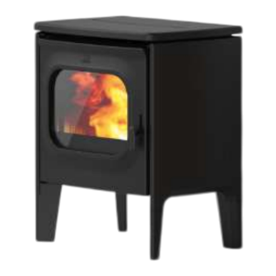
JØTUL PF 980
IT
- Manuale di installazione, uso e manutenzione
2
EN - Installation, operation and maintenance manual
66
PF 980
IT - Prima dell'uso, leggere attentamente le istruzioni generali di installazione, uso e manutenzione
EN - Before use, read the general instructions of installation, use and maintenance carefully
Le istruzioni fornite devono essere conservate per tutta la vita del prodotto. The instruction manual
provided with the product must be kept throughout the entire period of the products use.
Advertisement
Chapters
Table of Contents

Related Manuals for Jøtul PF 980


Summary of Contents for Jøtul PF 980
- Page 1 JØTUL PF 980 - Manuale di installazione, uso e manutenzione EN - Installation, operation and maintenance manual PF 980 IT - Prima dell’uso, leggere attentamente le istruzioni generali di installazione, uso e manutenzione EN - Before use, read the general instructions of installation, use and maintenance carefully Le istruzioni fornite devono essere conservate per tutta la vita del prodotto.
- Page 2 ITALIANO INFORMAZIONI PER APPARECCHI DI RISCALDAMENTO A COMBUSTIBILE SOLIDO In base al regolamento (UE) n. 1185/2015 Produttore Jotul Identificativo del modello PF 980 Marchio Jotul Funzionalità di riscaldamento indiretto Potenza termica diretta 8,8 kW Potenza termica indiretta -- kW Combustibile...
-
Page 3: Table Of Contents
ITALIANO INDICE 10.12 Termini e condizioni ..................40 10.13 Gestione accessi ....................40 10.14 Licenze opensource ....................41 10.15 Elimina account ....................41 IDENTIFICAZIONE ���������������������������������������������������������������������������������������4 10.16 Esci ........................41 Identificazione dell’apparecchio ................4 Identificazione del costruttore ................4 1.3 Norme di riferimento ..................4 MENÙ... -
Page 4: Identificazione ���������������������������������������������������������������������������������������4 10.15 Elimina Account
Assistenza Tecnica Autorizzata da Jøtul. 1�3 NORME DI RIFERIMENTO Tutti i diritti sono riservati. Nessuna parte di questo Le stufe PF 980 oggetto del presente manuale, sono manuale d’istruzioni potrà essere riprodotta o trasmessa conformi al regolamento: con qualsiasi mezzo elettronico o meccanico, incluso... -
Page 5: Garanzia
ITALIANO 2 GARANZIA 3 INFORMAZIONI GENERALI Prendere visione delle condizioni di garanzia sotto 3�1 FORNITURA E CONSERVAZIONE riportate. Il manuale è parte integrante ai fini della sicurezza, 2�1 CONDIZIONI DI GARANZIA pertanto: La garanzia al Cliente viene riconosciuta dal Rivenditore •... -
Page 6: Sicurezze
ITALIANO 4 SICUREZZE È v i e t a t o f a r f u n z i o n a r e l’apparecchio con la porta o 4�1 AVVERTENZE GENERALI cassetto ceneri aperti o con il DI SICUREZZA vetro rotto. -
Page 7: Rischi Residui
ITALIANO sistemi di sicurezza potrebbero RISCHIO DESCRIZIONE ED i n t e r v e n i r e s p e g n e n d o RESIDUO INFORMAZIONI l’apparecchio. Non disabilitare PROCEDURALI mai i sistemi di sicurezza. Quando l’apparecchio Per il collegamento diretto alla è... -
Page 8: Descrizione Dell'apparecchio
ITALIANO 5 DESCRIZIONE 5�2 USO SCORRETTO RAGIONEVOLMENTE DELL’APPARECCHIO PREVEDIBILE 5�1 USO PREVISTO L’uso scorretto ragionevolmente L’apparecchiatura in oggetto prevedibile, viene di seguito è destinata al riscaldamento elencato: degli ambienti domestici e/o • utilizzo dell’apparecchio come commerciali mediante inceneritore; combustione di pellet di legno; •... -
Page 9: Obblighi E Divieti
ITALIANO 5�3 OBBLIGHI E DIVIETI 5�3�2 Divieti 5�3�1 Obblighi L’utente non deve: • rimuovere o modificare senza L’utente deve: autorizzazione i dispositivi di • leggere il presente manuale sicurezza; istruzioni prima • utilizzare combustibili liquidi compiere qualsiasi operazione infiammabili per l’accensione; sull’apparecchio;... -
Page 10: Caratteristiche Del Pellet
L’utilizzo di combustibile non conforme a quanto sopra specificato fa decadere la garanzia. 5�5 DESCRIZIONE DEL FUNZIONAMENTO Le stufe a pellet Jøtul PF 980 sono apparecchi per il riscaldamento domestico alimentati a pellet di legno a caricamento automatico. Il calore generato dalla combustione del pellet viene diffuso nel locale di installazione grazie al sistema di ventilazione oltre che per irraggiamento. -
Page 11: Formazione Degli Utenti
ITALIANO 5�7 FORMAZIONE DEGLI UTENTI Se la ventola si ferma, la scheda Guasto ventola Una volta conclusa l’installazione l’utente finale deve elettronica blocca la fornitura di fumi essere sempre formato sulle funzioni e caratteristiche pellet e viene visualizzato l’allarme dell’apparecchio in modo esauriente dal tecnico Guasto autorizzato da Jøtul per garantirne un utilizzo ottimale e Se il motoriduttore si guasta, il... -
Page 12: Trasporto Einstallazione
ITALIANO 6 TRASPORTO E 3) Togliere l’eventuale involucro 4) Togliere l’apparecchio dal bancale e posizionare INSTALLAZIONE l’apparecchiatura nel luogo prescelto, facendo attenzione che sia conforme a quanto previsto. 6�1 AVVERTENZE DI SICUREZZA PER IL Per rimuovere le assi o parti in legno dell’imballo utilizzare TRASPORTO E L’INSTALLAZIONE adeguate attrezzature. -
Page 13: Installazione
ITALIANO comunque coibentata e può essere inserita in un cavedio non soddisfa questo requisito, occorre prendere misure purché rispetti le normative relative all’intubatura; appropriate (ad esempio utilizzando una piastra per la • il canale da fumo va collegato alla canna fumaria distribuzione del carico). - Page 14 ITALIANO della canna fumaria è stato montato un raccordo di tipo montato un raccordo di tipo “T” con tappo di ispezione. “T” con tappo di ispezione; in modo che il tratto esterno È sconsigliato installare come primo tratto iniziale una sia ispezionabile.
-
Page 15: Collegamenti
ITALIANO 7 COLLEGAMENTI 7�4 INSTALLAZIONE POSTERIORE (KIT OPZIONALE) I collegamenti devono essere eseguiti da un tecnico qualificato e/o autorizzato dal Costruttore. La tipologia di cavo da montare in caso di sostituzione, con relativa sezione, è: H05RR-F sez.3G0,75. 7�1 COLLEGAMENTO CON PRESA D’ARIA ESTERNA Per eseguire il collegamento con presa d’aria esterna, procedere come descritto di seguito:... -
Page 16: Collegamento Elettrico
ITALIANO 7�5 COLLEGAMENTO ELETTRICO La spina del cavo di alimentazione dell’apparecchio deve essere collegata solo dopo la conclusione dell’installazione e dell’assemblaggio dell’apparecchio, e deve rimanere accessibile dopo l’installazione. Per eseguire il collegamento elettrico, procedere come descritto di seguito: • Collegare il cavo di alimentazione prima alla spina sul retro dell’apparecchio e poi ad una presa elettrica a parete. -
Page 17: Procedure Preliminari
ITALIANO 8 PROCEDURE PRELIMINARI Una volta scaricata e installata l’applicazione procedere come di seguito. 8�1 CARICAMENTO PELLET Accettare le condizioni proposte mentre si usa l’app. La prima operazione da eseguire prima di accendere il prodotto è quella di riempire il serbatoio di combustibile (pellet) utilizzando preferibilmente una apposita paletta. -
Page 18: Creazione Di Un Account
ITALIANO 8�5 CREAZIONE DI UN ACCOUNT nuovamente la propria mail (Fig 8.7). Selezionando la voce “Submit” (Fig. 8.8) si riceverà Per creare un nuovo account, se non se ne possiede già un’ulteriore email; aprirla e selezionare la voce “Verify uno, selezionare la voce “Non hai un account?” Mail”... -
Page 19: Recupero Della Password
ITALIANO 8�6 RECUPERO DELLA PASSWORD Se si possiede già un account, ma non si ricorda la password, selezionare la voce “Password dimenticata?” e inserire l’email associata all’account di cui si vuole recuperare la password. Fig. 8.8 Fig. 8.11 Fig. 8.9 Fig. -
Page 20: Condizioni Di Utilizzo
ITALIANO Fig. 8.14 Prestare attenzione all’inserimento corretto dell’Email per il recupero. Nel caso l’Email non venga ricevuta, verificare che non sia stata inserita nella lista delle “spam/ posta indesiderata”. 8�7 CONDIZIONI DI UTILIZZO Il passo successivo alla creazione dell’account è accettare le condizioni di utilizzo. - Page 21 ITALIANO Scansionare il codice QR che si trova o sul retro del Inserire manualmente il nome della stufa (Fig. 8.20) o corpo della stufa o sul foglio di controllo, nella busta scegliere il nome tra quelli suggeriti (Fig. 8.21). pluriball contenuta all’interno della tramoggia. In alternativa, inserire il codice a 16 caratteri manualmente –...
- Page 22 ITALIANO Selezionare la rete Wi-Fi da utilizzare e inserire la Prima di eseguire il precarico della coclea assicurarsi di aver password. riempito il serbatoio del pellet e verificare che la coclea non sia già piena. Durante il precarico non aprire la porta della Successivamente scegliere il profilo di installazione della stufa.
- Page 23 ITALIANO 8�8�2 Errore di connessione con una nuova stufa • sulla schermata “Gestione accessi” cliccare sul bottone “Richiedi nuovo accesso” (Fig. 8.28); Se dovesse comparire il messaggio “Questa stufa è già • si aprirà una finestra di dialogo (Fig. 8.29); configurata, vuoi chiedere un permesso di accesso?”...
- Page 24 ITALIANO Fig. 8.28 Fig. 8.30 Fig. 8.31 Fig. 8.29...
- Page 25 ITALIANO Fig. 8.32 Fig. 8.34 Richiesta di accesso Adesso Il proprietario della stufa ha accettato la tua richiesta Fig. 8.35 8�8�4 Errore di connessione con una stufa già configurata Se dovesse comparire il messaggio “Si è verificato un errore” verificare: •...
-
Page 26: Telecomando O Schermata Iniziale
ITALIANO 9 TELECOMANDO O SCHERMATA INIZIALE 9�1 DESCRIZIONE Il telecomando è composto da: Nome della stufa Menù principale Tasto di accensione Bluetooth on/o Stato della stufa Wi-Fi on/o Temperatura desiderata Potenza di funzionamento desiderata Tipologia di gestione della potenza Potenza attuale della stufa Temperatura ambiente attuale Sonda ambiente attiva Accensione o spegnimento ritardati attivi... -
Page 27: Albero Di Navigazione
ITALIANO 9�2 ALBERO DI NAVIGAZIONE Storico Telecomando Pianificazione Menù principale Le mie stufe Supporto/Email xxxxx@email.com xxxxx@email.com Impostazioni Fig. 9.2... -
Page 28: Menù "Impostazioni
ITALIANO 10 MENÙ “IMPOSTAZIONI” Scorrere la pagina per vedere tutto l’elenco delle impostazioni possibili. 10�1 IMPOSTAZIONI Premere sulla voce desiderata per aprire la schermata di modifica o visualizzazione della stessa. Dal telecomando (o dalla schermata iniziale) premere sull’icona per accedere al menù principale. Premere poi sull’icona per accedere al menù... -
Page 29: Nome Stufa E Zone
ITALIANO 10�1�1 Lista impostazioni IMPOSTAZIONI SOTTOMENÙ DESCRIZIONE Consente di scegliere il nome da attribuire alla stufa e alle zone di Nome stufa e zone riscaldamento Configurazione stufa Consente di modificare alcuni parametri Rete Wi-Fi Consente di scegliere la rete Wi-Fi a cui collegare l’apparecchio Dettagli stufa Informazioni relative all’apparecchio Impostazioni stufa... - Page 30 ITALIANO 10�3�1 Lista configurazioni VALORI VALORI PARAMETRO DESCRIZIONE IMPOSTABILI DEFAULT È possibile impostare manualmente la posizione Posizione stufa Imposta geografica della stufa Precarico manuale Caricamento manuale della coclea Avvia; Interrompi Avvia È possibile impostare la modalità di utilizzo e la velocità Manuale;...
- Page 31 ITALIANO Fig. 10.9 Fig. 10.11 Per interromperla, invece: 10�3�4 Funzione “Velocità ventola zona 1” Questa funzione è utilizzabile solamente con stufa accesa (Fig. 10.13), altrimenti non sarà modificabile (Fig. 10.12). Sarà possibile scegliere tra funzionamento manuale o automatico. Nel caso in cui si scelga il funzionamento manuale sarà possibile modificare la velocità...
- Page 32 ITALIANO Fig. 10.13 Fig. 10.15 10�3�6 Funzione “Stand-by” Abilitando questa funzione si fa in modo che l’apparecchio, al raggiungimento della temperatura desiderata in ambiente, si spenga. Se tale funzione non è abilitata, l’apparecchio modula il proprio funzionamento non spegnendosi. Per attivare tale funzione premere il tasto “On”. Fig.
- Page 33 ITALIANO 10�3�7 Funzione “Silenzia buzzer” 10�3�9 Funzione “Resetta pianificazione” Per resettare la pianificazione premere il tasto “Reset”. Questa funzione è utilizzabile solamente quando un allarme è presente, altrimenti non sarà utilizzabile. Per silenziare temporaneamente il cicalino premere il tasto “Silenzia”. Fig.
- Page 34 ITALIANO Fig. 10.21 Fig. 10.23 10�3�11 Funzione “Spegnimento ritardato” 10�3�12 Funzione “Offset zona 1” Tramite questa funzione è possibile ritardare lo Questa funzione permette di correggere la lettura della spegnimento dell’apparecchio solo se quest’ultimo è temperatura ambiente della zona 1. acceso e se la pianificazione non è...
- Page 35 ITALIANO 10�3�13 Funzione “Termostato” e collegarlo al connettore EP 10 della scheda elettronica come mostrato in figura. Quando l’apparecchio viene comandato da un termostato (o cronotermostato) esterno l’installatore deve attivarlo tramite il tasto “On” EP10 Procedere manualmente alla sostituzione della sonda ambiente con il termostato esterno, tramite modifica del cablaggio (kit opzionale).
-
Page 36: Rete Wi-Fi
ITALIANO 10�4 RETE WI-FI 10�5 DETTAGLI STUFA Dalla lista delle impostazioni selezionare la voce “Rete Wi- È possibile visualizzare alcune delle informazioni relative Fi” per selezionare la rete a cui collegare l’apparecchio. all’apparecchio, attraverso lo scorrimento della schermata. Wi-Fi 1 Jotul Fig. -
Page 37: Storico Eventi
ITALIANO 10�6 STORICO EVENTI 10�7 STATISTICHE La lista riporta gli eventi verificatesi nell’apparecchio, in La lista riporta la registrazione del modo e delle ore di ordine temporale, secondo la suddivisione riportata nella funzionamento, in ordine temporale. seguente tabella: Scorrendo la schermata sarà possibile visualizzare tutte le statistiche acquisite. -
Page 38: Aggiornamento Ble
ITALIANO 10�8 AGGIORNAMENTO BLE Nel caso in cui il dispositivo smart abbia la connessione dati attiva e il software presente sulla stufa sia di una versione antecedente all’ultima rilasciata, appare un messaggio all’apertura dell’applicazione (Fig. 10.33). Qualora l’utente non visualizzasse il messaggio all’apertura dell’applicazione, potrà... -
Page 39: Reset Dati Fabbrica
ITALIANO 10�9 RESET DATI FABBRICA Dalla lista delle impostazioni, selezionare la voce “Reset dati fabbrica” per ripristinare i dati impostati dal costruttore e azzerare gli account essa associati (compreso l’account “proprietario”). Prima di effettuare un “Reset dati di fabbrica”, si deve: •... -
Page 40: Termini E Condizioni
ITALIANO 10�11 CAMBIA PASSWORD 10�12 TERMINI E CONDIZIONI Tramite questa schermata sarà possibile cambiare la Tramite questa schermata sarà possibile cambiare password dell’account utilizzato per la registrazione. i termini e le condizioni della privacy, tranne quelli obbligatori precedentemente selezionati durante la prima configurazione dell’applicazione. -
Page 41: Licenze Opensource
ITALIANO 10�14 LICENZE OPENSOURCE Dalla lista delle impostazioni, selezionando la voce “Licenze opensource” si aprirà una schermata in cui sarà possibile visualizzare le licenze dell’applicazione. Fig. 10.45 Questa azione non è reversibile. È necessario contattare un Centro Assistenza Autorizzato per ripristinarlo. 10�16 ESCI Fig. -
Page 42: Menù "Pianificazione
ITALIANO 11 MENÙ “PIANIFICAZIONE” 11�1 PIANIFICAZIONE Dal menù principale premere sull’icona per accedere al menù “Pianificazione”. Da questa schermata (Fig. 11.2) sarà possibile pianificare il funzionamento dell’apparecchio e la temperatura desidera nell’arco della giornata, per ogni giorno della settimana; essa si presenterà di default come nella figura riportata. Premere sul giorno desiderato per aprire la schermata di modifica dello stesso. -
Page 43: Descrizione
ITALIANO 11�2 DESCRIZIONE A ciascun giorno della settimana è possibile assegnare diverse fasce orarie con temperature differenti, una ogni 15 minuti. Per ciascuna fascia si può impostare: ora di inizio, ora di fine e temperatura desiderata. Sarà sempre possibile creare o eliminare nuove fasce e copiare l’intera pianificazione della giornata per gli altri giorni della settimana. -
Page 44: Utilizzo
ITALIANO 11�3 UTILIZZO fascia, in modo analogo alle operazioni precedenti. Le temperature impostabili sono: OFF (stufa spenta) e 11�3�1 Gestione delle fasce orarie da 10°C a 30°C. Per modificare l’orario di inizio premere il pulsante, indicante l’ora, sotto la parola “Inizio”. Agendo sui tasti scelgo l’orario di inizio della fascia. -
Page 45: Reset Della Pianificazione
ITALIANO 12 MENÙ “STORICO” 11�3�3 Copiare la pianificazione di un giorno Esempio: se volessi copiare la pianificazione fatta per 12�1 STORICO lunedì anche per martedì basterebbe premere sull’icona e selezionare “martedì”. Dal menù principale premere sull’icona per accedere al menù “Storico”. Da questa schermata (Fig. -
Page 46: Menù "Le Mie Stufe
ITALIANO 13 MENÙ “LE MIE STUFE” 14 MENÙ “SUPPORTO” 13�1 LE MIE STUFE 14�1 SUPPORTO Dal menù principale premere sull’icona per accedere Dal menù principale premendo sull’icona si verrà al “Le mie stufe”. reindirizzati alla propria mail per la richiesta di supporto. Da questa schermata (Fig. -
Page 47: Utilizzo
ITALIANO 15 UTILIZZO Accensione automatica: l’apparecchio è dotato di un dispositivo automatico che consente l’accensione del pellet 15�1 ACCENSIONE senza l’utilizzo di altri accenditori tradizionali. Evitare di accendere manualmente l’apparecchio se il Prima di ogni accensione, accertarsi che il cassetto cenere sistema di accensione automatico è... -
Page 48: Modifica Dei Parametri
ITALIANO Fig. 15.8 Fig. 15.5 Fig. 15.9 Fig. 15.6 I valori impostati verranno mantenuti fino alla successiva 15�4 MODIFICA DEI PARAMETRI variazione, anche ad apparecchio spento o scollegato È possibile modificare alcuni parametri di funzionamento dall’alimentazione elettrica. secondo quanto riportato al capitolo “Menù Impostazioni”. Si raccomanda di spegnere l’apparecchio seguendo Per effettuare una nuova accensione si consiglia di scrupolosamente quanto sopra riportato. -
Page 49: Anomalie E Possibili Rimedi
ITALIANO 16 ANOMALIE E POSSIBILI RIMEDI Quando si verifica un’anomalia di funzionamento viene attivato un allarme acustico (beep) e nell’applicazione appare la possibile causa con una breve descrizione. Gli errori sono suddivisi in: • Warning (avviso) : semplici avvertimenti che non bloccano il funzionamento dell’apparecchio (in alcuni casi lo limitano). -
Page 50: Tabella Riassuntiva Delle Possibili Anomalie
ITALIANO 16�4 TABELLA RIASSUNTIVA DELLE POSSIBILI ANOMALIE TIPOLOGIA TESTO VISUALIZZATO MOTIVAZIONE POSSIBILI SOLUZIONI Errore HW trasduttore Mancato o non corretto collegamento delle Verificare il collegamento delle pressione aria (AL 14) prese di pressione prese di pressione Verificare la presenza di pellet nel Mancanza pellet (AL 33) Pellet in esaurimento serbatoio. -
Page 51: 17 Pannello Comandi
ITALIANO TIPOLOGIA TESTO VISUALIZZATO MOTIVAZIONE POSSIBILI SOLUZIONI Allarme sovratemperatura Intervento del termostato a riarmo serbatoio pellet (AL 01) automatico collegato alla tramoggia Sovratemperatura scheda (AL Superamento della temperatura massima ammessa per la scheda Errore HW sonda fumi (AL Sonda guasta o interrotta Critical Sovratemperatura fumi (AL Superamento della temperatura massima... -
Page 52: Descrizione
ITALIANO 17�2 VISUALIZZAZIONI DI STATO ICONA STATO DESCRIZIONE Connessione al servizio Cloud valida, con indicazione della qualità del Accesa segnale Animazione crescente Connessione Wi-Fi in corso o parametri Wi-Fi non validi Spenta Parametri Wi-Fi non impostati Spenta Stufa spenta Animazione accensione Stufa in fase di accensione Animazione spegnimento Stufa in fase di spegnimento automatico... -
Page 53: Manutenzione
ITALIANO 18 MANUTENZIONE 17�3�1 Menù utente del pannello comandi Dopo aver tenuto premuto il tasto verranno visualizzati 18�1 AVVERTENZE DI SICUREZZA PER LA e sarà possibile modificare, in ordine progressivo, le MANUTENZIONE seguenti voci: La manutenzione dell’apparecchio deve essere effettuata DESCRIZIONE VALORI almeno una volta all’anno, e programmata per tempo con... - Page 54 ITALIANO 18�2�1 Pulizia del braciere 18�2�4 Pulizia della camera di combustione E’ necessario controllare che il braciere dove avviene la Per eseguire la pulizia della camera di combustione combustione sia ben pulito e che scorie o residui non procedere come descritto di seguito: ne ostruiscano i fori.
-
Page 55: Manutenzione Programmata
ITALIANO 18�2�6 Pulizia del condotto di aspirazione Verificare periodicamente che il condotto di aspirazione sia libero da ostruzioni (polveri, peli di animali...) ed eventualmente rimuoverle. 18�3 MANUTENZIONE PROGRAMMATA Le operazioni di manutenzione devono essere eseguite a stufa fredda e con alimentazione elettrica disconnessa. Le operazioni di manutenzione programmata devono essere eseguite da personale del Centro di Assistenza Autorizzato. - Page 56 ITALIANO Fig. 18.9 Fig. 18.12 Dopo aver effettuato la pulizia della camera di combustione si consiglia di procedere con la pulizia delle botole di ispezione come indicato nel paragrafo “Pulizia condotto fumi“. 18�3�2 Controllo delle guarnizioni Questa operazione deve essere svolta da un Centro Assistenza Jøtul.
- Page 57 ITALIANO 18�3�3 Pulizia condotto fumi Questa operazione deve essere svolta da un Centro Assistenza Jøtul. Programmare con il Centro Assistenza Jøtul questo tipo di pulizia. L’apparecchio è dotata di alcune botole per la pulizia dei condotti fumo interni. Per effettuare la pulizia dei condotti fumo, procedere come descritto di seguito: PASSO AZIONE...
-
Page 58: 19 Casistica Guasti
ITALIANO 19 CASISTICA GUASTI 20 SMALTIMENTO A FINE VITA 19�1 L’APPARECCHIO NON FUNZIONA 20�1 AVVERTENZE PER IL CORRETTO SMALTIMENTO DEL PRODOTTO • Seguire attentamente quello che è riportato nel capitolo dedicato di questo manuale; La demolizione e lo smaltimento dell’apparecchio è ad •... - Page 59 ITALIANO Se presente smaltire separatamente secondo il materiale che lo compone: - Metallo - Vetro RIVESTIMENTO - Mattonelle o ceramica ESTERNO - Pietra - Legno Se presente smaltire separatamente secondo il materiale che lo compone: - Vetroceramico (porta fuoco): smaltire negli inerti o rifiuti misti VETRI PORTE - Vetro temperato (porta forno): smaltire nel vetro Se presente smaltire separatamente secondo il materiale che lo compone:...
-
Page 60: Schema Di Collegamento Elettrico
ITALIANO SCHEMA DI COLLEGAMENTO ELETTRICO PF 980 MOTORIDUTTORE PULITORE FUSIBILE DI SICUREZZA INGRESSO (5A) P.E. EP18 RETE P.E. 230V AC Sensore hall 1 CANDELETTA CAND - N VENTOLA FUMI CAND - L Sensore hall 1 V.FUMI - N (ventola fumi) V.FUMI - L... -
Page 61: Dati Tecnici
ITALIANO DATI TECNICI PF 980 (in conformità con la norma EN 14785) UNITÀ DI MISURA PF 980 ⭐ Classe di qualità ambientale Classe di efficienza energetica Potenza introdotta Rid. - Nom. 4,2 - 10 Potenza resa Rid. - Nom. 3,9 - 8,8 Rendimento Rid. -
Page 62: Descrizione
ITALIANO DESCRIZIONE PF 980 USCITA ARIA CALDA PORTA CAMERA DI COMBUSTIONE GRIGLIA PER LA CENERE BRACIERE CASSETTO CENERE SERBATOIO PELLET SPORTELLO SERBATOIO PELLET CONNETTORE PER PANNELLO COMANDI... -
Page 63: Dimensioni
ITALIANO DIMENSIONI PF 980 80 USCITA FUMI 80 USCITA FUMI OPZIONALE 50 ENTRATA ARIA UNITÀ DI PF 980 MISURA ALTEZZA LARGHEZZA PROFONDITÀ PESO A VUOTO... -
Page 64: Etichetta
ITALIANO ETICHETTA CE PF 980 Nell’etichetta sono utilizzati i seguenti simboli Model: PF 980 APPARECCHIO PER IL RISCALDAMENTO DOMESTICO ALIMENTATO A PELLET DI LEGNO Potenza introdotta (max) RESIDENTIAL SPACE HEATING APPLIANCE FIRED BY WOOD PELLETS IN,nom APPAREIL DE CHAUFFAGE DOMESTIQUE À CONVECTION À GRANULES DE BOIS... - Page 65 ITALIANO...
- Page 66 ENGLISH INFORMATION ON SOLID FUEL HEATING APPLIANCES According to Regulation (EU) No. 1185/2015 Manufacturer Jotul Model identifier(s) PF 980 Brand Jotul Indirect heating functionality Direct heat output 8,8 kW Indirect heat output -- kW Other η Preferred fuel Space heating emissions at...
- Page 67 ENGLISH TABLE OF CONTENTS 10.12 Terms and conditions ..................103 10.13 Access manager ....................103 10.14 Opensource licenses ..................104 10.15 Delete account ....................104 IDENTIFICATION ����������������������������������������������������������������������������������������68 10.16 Exit ........................104 Stove identification ....................68 Manufacturer Identification ................68 1.3 Reference standards ..................68 “PLANNING”...
-
Page 68: Identification ����������������������������������������������������������������������������������������68 10.15 Delete Account
All rights reserved. No part of this instructions manual 1�3 REFERENCE STANDARDS can be reproduced or transmitted through any electronic The stoves PF 980 that this manual refers to are or mechanical means, including photocopies, recordings compliant with the regulation:... -
Page 69: Warranty
ENGLISH 2 WARRANTY 3 GENERAL INFORMATION Read the warranty conditions contained below. 3�1 SUPPLY AND SAFE-KEEPING 2�1 WARRANTY CONDITIONS The manual is supplied in printed format. For a user to be able to take advantage of the legal Keep this manual safe, with the appliance, so that the user guarantee as per Directive 1999/44/EC, they must can consult it easily. -
Page 70: Safety Measures
ENGLISH 4 SAFETY MEASURES reach hot temperatures to the touch. 4�1 GENERAL SAFETY The appliance may be used by WARNINGS children of at least 8 years of Read this instructions manual age and by persons with reduced carefully before appliance physical, sensory or mental installation and use. -
Page 71: Residual Risks
ENGLISH 5 DESCRIPTION OF THE category III, in accordance with the installation rules. APPLIANCE 4�2 RESIDUAL RISKS 5�1 INTENDED USE The appliance was designed so as The appliance in question is to guarantee the user’s essential intended for domestic and/or safety requirements. -
Page 72: Obligations And Forbidden Actions
ENGLISH • using the appliance with liquid • keep objects that are not heat fuels; and/or flame-resistant at a • using the appliance with the safe distance; door open and the ash drawer • only and exclusively load the out. appliance with pellet with Any use of the appliance the characteristics described... -
Page 73: Characteristics Of The Fuel
Using fuel that is not compliant with the above will void the warranty. 5�5 DESCRIPTION OF OPERATION Jøtul PF 980 pellet stoves are home heating appliances powered by wood pellets with automatic loading. The heat generated by the combustion of the pellets is diffused in the installation room thanks to the ventilation system as well as by radiation. -
Page 74: User Training
ENGLISH If the anomalies listed below occur, the stove automatically switches itself off: ANOMALIES DESCRIPTION If the temperature probe at High/low the smoke outlet detects temperature in temperatures that are too high, the combustion the stove is switched off and the chamber relative alarm is displayed If the fan stops, the electronic... -
Page 75: Shipping And Installation
ENGLISH 6 SHIPPING AND compliant with the directions. INSTALLATION Use suitable equipment to remove the boards or wooden parts of packing. 6�1 SAFETY WARNINGS FOR The end user is responsible for disposing of the packaging TRANSPORTATION AND in accordance with the laws in force in the country of INSTALLATION installation. -
Page 76: Installation
ENGLISH type of insulating material that needs to be used is on the area bounded by the minimum distances indicated above. chimney data plate. Appliance installation must guarantee easy access to clean the appliance, the exhaust ducts and the chimney. Use watertight pipes with silicone seals. - Page 77 ENGLISH installed with inspection cap just like for the chimney pot. It is prohibited to install a 90° bend for the initial segment, since the ashes would quickly obstruct smoke passage, causing draught problems in the stove. (Fig. 6.2) Fig. 6.3 This type of installation (Fig.
-
Page 78: Connections
ENGLISH 7 CONNECTIONS 7.4 REAR INSTALLATION (OPTIONAL KIT) The connections must be set up by a technician that is qualified and/or authorised by the Manufacturer. By the installer the type of cable, with relative section, to be installed in case of replacement is: H05RR-F sez.3G0,75 7�1 CONNECTION WITH EXTERNAL AIR INTAKE... -
Page 79: Electrical Connection
ENGLISH 7�5 ELECTRICAL CONNECTION The plug of the stove’s power cable must only be connected after the installation and assembly has been completed appliance, must remain accessible after installation. To make the electrical connection, proceed as described below: • First connect the power cable to the plug on the back of the stove and then to a wall socket. -
Page 80: Preliminary Procedures �������������������������������������������������������������� 80 18.2 Cleaning
ENGLISH 8 PRELIMINARY PROCEDURES Once the application has been downloaded and installed, proceed as follows. 8�1 PELLET LOADING Accept the suggested conditions while using the App. The first operation to do before turning on the product is to fill the fuel hopper (pellet) preferably using a special pan. -
Page 81: Creating An Account
ENGLISH 8�5 CREATING AN ACCOUNT By selecting “Submit” (Fig. 8.8) you will receive an additional email; open it and select “Verify Mail” (Fig. To create a new account, if you do not already have one, 8.9), which will redirect to the verification confirmation select “I don’t have an account”. -
Page 82: Password Recovery
ENGLISH 8�6 PASSWORD RECOVERY If you already have an account but do not remember your password, select “Forgot password?” and enter the email associated to the account that you wish to recover the password for. Fig. 8.8 Fig. 8.11 Fig. 8.9 Fig. -
Page 83: Conditions Of Use
ENGLISH Fig. 8.14 Be sure to correctly enter the Email for recovery. If you do not get the Email, check whether it has been sent to the “spam” / “junk” list. 8�7 CONDITIONS OF USE The next step to create an account is to accept the conditions of use. - Page 84 ENGLISH Scan the QR code located either on the back of the body Manually enter the stove label (Fig. 8.20) or choose a of the stove or on the check sheet, in the bubble-wrap name from the suggestions (Fig. 8.21). bag contained inside the hopper.
- Page 85 ENGLISH Select the Wi-Fi network and enter the password. Before preloading the auger, be sure you have filled the pellet hopper and check that the auger is not already full. Then choose the stove installation profile. During preloading do not open the stove door. After filling the stove hopper, start auger preloading.
- Page 86 ENGLISH 8.8.2 Connection error with new stove • in “Serial code” enter the stove code manually (all 16 characters, no spaces) If this message appears “This stove is already setup. Do • in “Message” it is not compulsory to enter anything you want to request an access permission?”...
- Page 87 ENGLISH Fig. 8.28 Fig. 8.30 Fig. 8.31 Fig. 8.29...
- Page 88 ENGLISH Fig. 8.32 Fig. 8.34 Request for access The stove owner has accepted your request Fig. 8.35 8.8.4 Connection error with an already configured stove If the “An error has occurred” message appears, check: • that the stove’s 16-digit code has been entered correctly; •...
-
Page 89: Remote Control Or Home Page �������������������������������������������������89 20 Disposal At End Of Service Life
ENGLISH 9 REMOTE CONTROL OR HOME PAGE 9�1 DESCRIPTION The remote control is composed of: Stove label Main menu Switching on button Bluetooth on/o Stove status Wi-Fi on/o Desired temperature Desired operating power Type of power management Current stove power Current room temperature Room probe enabled Delayed switching on or switching o enabled... -
Page 90: Navigation Tree
ENGLISH 9�2 NAVIGATION TREE History Remote control Planning Main Menu My stoves Supporto/Email xxxxx@email.com xxxxx@email.com Settings Fig. 9.2... -
Page 91: 10 "Settings" Menu
ENGLISH 10 “SETTINGS” MENU Scroll the page to see the full list of possible settings. Press the required item to open its editing or viewing 10�1 SETTINGS screen. From the remote control (or home page) press the icon to access the main menu. Then press the to access the “Settings”... -
Page 92: Exit
ENGLISH 10.1.1 List of Settings SETTINGS SUB-MENU DESCRIPTION Stove and zones name Allows you to choose the name to be given to the stove and heating zones Stove configuration To edit some parameters Wi-Fi To choose the Wi-Fi network to connect the appliance to Stove details Information about the appliance Stove settings... - Page 93 ENGLISH 10.3.1 Parameter List SETTABLE DEFAULT PARAMETER DESCRIPTION VALUES VALUES The geographical location of the stove can be set Stove location Get position manually Manual preload Manual loading of the auger Start; Stop Start Manual; Auto; Fan speed zone 1 You can set the usage mode and fan speed of zone 1 Auto 1...5 (Manual)
- Page 94 ENGLISH Fig. 10.9 Fig. 10.11 On the other hand, to pause it: 10.3.4 “Fan speed zone 1” function This function can only be used with the stove on (Fig. 10.13), otherwise it cannot be changed (Fig. 10.12). You can choose between manual or automatic operation. If manual operation is chosen, the fan speed can be changed.
- Page 95 ENGLISH Fig. 10.13 Fig. 10.15 10.3.6 “Stand-by” function By enabling this function the appliance reaches the desired room temperature and then switches off. If this function is not enabled, the appliance modulates its operation by not switching off. To enable this function press “On”. Fig.
- Page 96 ENGLISH 10.3.7 “Silence buzzer” function 10.3.9 “Reset planning” function To reset planning press “Reset”. This function can only be used when an alarm is present, otherwise it will not be usable. To silence the buzzer temporarily, press “Silence”. Fig. 10.19 10.3.10 “Delayed ignition”...
- Page 97 ENGLISH Fig. 10.21 Fig. 10.23 10.3.11 “Delayed shutdown” function 10.3.12 “Offset zone 1” function This function allows you to delay switching off the This function is used to correctly read room temperature appliance only if this is switched on and if the schedule of zone 1.
- Page 98 ENGLISH 10.3.13 “Thermostat” function and connect it to the EP 10 connector on the electronic board as shown in the figure. When the appliance is controlled by an external thermostat (or chronothermostat), the installer must turn it on using the “On” button EP10 Manually proceed with replacing the room probe with the external thermostat, by changing the wiring (optional kit).
-
Page 99: Wi-Fi
ENGLISH 10�4 WI-FI 10�5 STOVE DETAILS From the list of settings, select “Wi-Fi” to select which It is possible to view some of the information relative to network to connect the appliance to. the appliance, by scrolling the screen. Wi-Fi 1 Jotul Fig. -
Page 100: Events History
ENGLISH 10�6 EVENTS HISTORY 10�7 STATISTICS The list includes the events that happened on the The list of recorded mode and operating hours, in appliance, in chronological order, according to the division chronological order. reported in the table below: By scrolling the screen it will be possible to view all of the acquired statistics. -
Page 101: Ble Update
ENGLISH 10�8 BLE UPDATE In the event that the smart device has an active data connection and the software on the stove is of a version prior to the latest release, a message appears when opening the application (Fig. 10.33). If the user does not see the message when opening the application, he can always select the “BLE update”... -
Page 102: Factory Reset
ENGLISH 10�9 FACTORY RESET From the list of settings, select “Factory reset” to restore the data set by the manufacturer and clear the accounts associated to it (including the “owner” account). Before running a “Factory reset” you must: • place the stove in “off” without any active errors; •... -
Page 103: Terms And Conditions
ENGLISH 10�11 CHANGE PASSWORD 10�12 TERMS AND CONDITIONS From this screen you can change the password of the From this screen you can change the privacy terms and account used for signing in. conditions, except for the compulsory ones selected previously during the first configuration of the application. -
Page 104: Opensource Licenses
ENGLISH 10�14 OPENSOURCE LICENSES From the settings list, select “Opensource licenses” to open a screen displaying the licenses of the application. Fig. 10.45 This action is not reversible. You must contact an Authorised Service Centre to reset it. 10�16 EXIT Fig. -
Page 105: 11 "Planning" Menu
ENGLISH 11 “PLANNING” MENU 11�1 PLANNING From the main menu, press the icon to access the “Planning” menu. From this screen (Fig. 81), it will be possible to plan appliance operation and the desired temperature over the course of the day, for each day of the week. By default, this will appear as shown in the picture. -
Page 106: Description
ENGLISH 11�2 DESCRIPTION For each day of the week, it is possible to assign various time slots with different temperatures, one every 15 minutes. For each slot you can set: start time, end time and desired temperature. It will always be possible to create or delete new time slots and copy the entire schedule of the day to the other days of the week. -
Page 107: Use
ENGLISH 11�3 USE The settable temperatures are: OFF (stove off) and from 10°C to 30°C. 11.3.1 Managing time slots Change the start time by pressing the button, indicating the time, under the word “Start”. Use the buttons to choose the start time of the slot. -
Page 108: Reset Planning
ENGLISH 12 “HISTORY” MENU 11.3.3 Copying the planning of a day Example: if you wish to copy Monday’s planning on 12�1 HISTORY Tuesday as well, simply press the icon and select “Tuesday”. From the main menu, press the icon to access the “History”... -
Page 109: 13 "My Stoves" Menu
ENGLISH 13 “MY STOVES” MENU 14 “SUPPORT” MENU 13�1 MY STOVES 14�1 SUPPORT From the main menu, press the icon to access the From the main menu press the icon to go to your “My stoves” menu. email to send the support request. From this screen (Fig. -
Page 110: 15 Use
ENGLISH 15 USE Automatic switching on: the appliance is equipped with an automatic device that switches on the pellet without 15�1 SWITCHING ON using other igniters. Avoid switching the appliance on manually if the automatic Before each switching on, make sure that the ash drawer switching on system is compromised. -
Page 111: Setting The Parameters
ENGLISH Fig. 15.8 Fig. 15.5 Fig. 15.9 Fig. 15.6 The set values will apply until the next variation, also 15�4 SETTING THE PARAMETERS with the appliance switched off or disconnected from the It is possible to change some of the operating parameters electrical power supply. -
Page 112: Anomalies And Possible Remedies
ENGLISH 16 ANOMALIES AND POSSIBLE REMEDIES When an operating anomaly happens, an audible alarm sounds (beep) and the possible cause appears in the application with a brief description. The errors are divided into: • Warning: simple warning that do not stop appliance operation (in some cases it can limit it). -
Page 113: Outlining Table Of Possible Anomalies
ENGLISH 16�4 OUTLINING TABLE OF POSSIBLE ANOMALIES TYPE DISPLAYED TEXT REASON POSSIBLE SOLUTIONS Air pressure transducer HW No or incorrect connection of the pressure Check the connection of the error (AL 14) outlets pressure outlets Verify pellet presence in the tank. Pellet shortage (AL 33) Pellets running low Load if needed. -
Page 114: Control Panel
ENGLISH TYPE DISPLAYED TEXT REASON POSSIBLE SOLUTIONS Pellet hopper over- Automatic re-arming thermostat connected temperature alarm to the hopper has tripped (AL 01) Board over-temperature (AL The maximum temperature allowed for the board has been exceeded HW error flue gas probe (AL Faulty or blown probe Smoke over-temperature (AL The maximum temperature allowed for the... -
Page 115: Description
ENGLISH 17�2 STATUS VIEWS ICON STATUS DESCRIPTION Valid connection to the Cloud service, with indication of signal quality Increasing animation Wi-Fi connecting or invalid Wi-Fi parameters Wi-Fi parameters not entered Stove off Switching on animation Stove in switching on phase Switching off animation Stove in automatic switching off phase Flashing... -
Page 116: Maintenance
ENGLISH 18 MAINTENANCE 17.3.1 Control panel user menu After pressing the key the following items will appear 18�1 SAFETY WARNINGS FOR in ascending order and it will be possible to edit them: MAINTENANCE DESCRIPTION VALUES Maintenance of the stove must be performed at least once Enable weekly a year and should be planned in advance with the Technical P on, P oFF... - Page 117 ENGLISH 18.2.1 Fire pot cleaning 18.2.4 Combustion chamber cleaning It is necessary to check that the fire pot where combustion To clean the combustion chamber, proceed as described takes place is well cleaned and that slag or residues do not below: obstruct the holes.
-
Page 118: Extraordinary Maintenance
ENGLISH 18.2.6 Air intake duct cleaning Periodically check that the air intake duct is free from obstructions (dust, animal hair ...) and remove them if necessary. 18�3 EXTRAORDINARY MAINTENANCE Maintenance operations must be carried out with the stove cold and with the power supply disconnected. Extraordinary maintenance activities must be carried out by staff from the Authorised Assistance Centre. - Page 119 ENGLISH Fig. 18.9 Fig. 18.12 After cleaning the combustion chamber, it is advisable to proceed with the cleaning of the inspection hatches as indicated in the paragraph “Smoke duct cleaning”. 18.3.2 Checking the gaskets This operation must be carried out by a Jøtul Service Centre.
- Page 120 ENGLISH 18.3.3 Smoke duct cleaning This operation must be carried out by a Jøtul Assistance Centre. Schedule this type of cleaning with the Jøtul Assistance Centre. The stove is equipped with some hatches for cleaning the internal smoke ducts. To clean the smoke ducts, proceed as described below: STEP ACTION Remove the right side (Fig.
-
Page 121: 19 Troubleshooting
ENGLISH 19 TROUBLESHOOTING 20 DISPOSAL AT END OF SERVICE LIFE 19�1 THE STOVE DOES NOT WORK • closely follow the directions in the dedicated chapter of this 20�1 WARNINGS FOR CORRECT DISPOSAL manual. OF THE PRODUCT • make sure that the air intake duct is not obstructed; Demolition and disposal of the stove is under the exclusive •... - Page 122 ENGLISH If present, dispose of it according to the material it is made of: - Metal - Glass EXTERNAL - Tiles or ceramic CLADDING - Stone - Wood If present, dispose of it according to the material it is made of: - Glass-ceramics (fire door): dispose of with inert or mixed waste DOOR GLAZING - Tempered glass (oven door): dispose of in glass...
-
Page 123: Connection Diagram
ENGLISH CONNECTION DIAGRAM PF 980 AUTOMATIC CLEANING SYSTEM FUSE (5A) P.E. EP18 P.E. POWER 230V AC Hall sensor 1 IGNITER CAND - N FLUE FAN CAND - L Hall sensor 1 V.FUMI - N (flue fan) V.FUMI - L V.AMB1 - N V.AMB1 - L... -
Page 124: Technical Data
ENGLISH TECHNICAL DATA PF 980 (according to standard EN 14785) UNIT OF PF 980 MEASUREMENT Energy efficiency class 4,2 - 10 Heating input reduced - nominal 3,9 - 8,8 Heating output reduced - nominal 92,5 - 88,2 Red. - Nom. Yield... -
Page 125: Description
ENGLISH DESCRIPTION PF 980 HOT AIR OUTLETS DOOR COMBUSTION CHAMBER ASH GRID FIRE POT ASH DRAWER PELLET TANK PELLET TANK COVER CONTROL PANEL CONNECTOR... -
Page 126: Dimensions
ENGLISH DIMENSIONS PF 980 80 SMOKE OUTLET 80 SMOKE OUTLET (OPTIONAL) 50 AIR INLET UNIT OF PF 980 MEASUREMENT HEIGHT WIDTH DEPTH WEIGHT... -
Page 127: Ce Label
ENGLISH CE LABEL PF 980 The following symbols are used on the label: Model: PF 980 APPARECCHIO PER IL RISCALDAMENTO DOMESTICO ALIMENTATO A PELLET DI LEGNO Heat input power (max) RESIDENTIAL SPACE HEATING APPLIANCE FIRED BY WOOD PELLETS IN,nom APPAREIL DE CHAUFFAGE DOMESTIQUE À CONVECTION À GRANULES DE BOIS... - Page 128 ITA-Informazioni per la gestione di rifiuti di apparecchiature elettriche ed elettroniche contenenti pile e accumulatori Questo simbolo che appare sul prodotto, sulle pile, sugli accumulatori oppure sulla loro confezione o sulla loro documentazione, indica che il prodotto e le pile o gli accumulatori inclusi al termine del ciclo di vita utile non devono essere raccolti, recuperati o smaltiti assieme ai rifiuti domestici.
- Page 129 ESP-Información para la gestión de residuos de aparatos eléctricos y electrónicos con pilas y acumuladores Este símbolo que aparece en el producto, en las pilas, los acumuladores o en su embalaje o su documentación indica que el producto y las pilas o acumuladores que contiene, al final de su vida útil, no deben recogerse, recuperarse o desecharse junto con los residuos domésticos.
- Page 132 JØTUL si impegna costantemente per migliorare i propri prodotti. Pertanto, si riserva il diritto di modificare specifiche, colori e dotazioni senza preavviso. JØTUL continuously strives to improve its products. In relation to this, it reserves the right to change specifications, colours and accessories without prior notice. Jøtul AS P.o.
Need help?
Do you have a question about the PF 980 and is the answer not in the manual?
Questions and answers