
Subscribe to Our Youtube Channel
Related Manuals for HANGCHA HV Series


Summary of Contents for HANGCHA HV Series
- Page 1 Series Mast-type Aerial Work HV120AJ Platform Operation Manual Hangcha Group Co., Ltd. March 2024...
-
Page 2: Table Of Contents
Please read, understand and follow these safety rules and operating instructions before you operate the machine. Only trained and authorized personnel are allowed to operate the machine. This manual shall always be kept with the machine as part of it. Please contact Hangcha Group if you have any questions. - Page 3 Please contact us if there is anything ambiguous in this manual or something you think should be added. Internet URL: www.zjhc.cn E-mail: sales@zjhc.cn Hotline: 400-884-7888 Hangcha Group Co., Ltd. All rights reserved First Edition: March 2024...
- Page 4 Danger Failure to follow the instructions and safety rules in this manual will lead to death or more serious injuries Cannot be operated unless: ☑ You have understood and practiced the rules for safe operation of the machine in this operation manual.
- Page 5 Classification of dangers: The symbols, color codes and symbol text used for product labels of Hangcha Group have the following meanings: Safety warning sign — used to indicate the potential personal injury. Observe all safety tips following this sign to avoid possible personal injury or death.
-
Page 6: Safety Rules
Safety Rules Conditions related to equipment use □ The ground of the workplace must be flat and solid, and there is enough distance between the overhead barrier-free equipment and the high-voltage line. □ The ambient temperature shall be within the range of -20°C ~ 40°C; altitude ≤1000m. □... - Page 7 electric shock Danger of The machine is not insulated and does not provide shock protection when touching or approaching wires. Maintain a sufficient safety distance from power lines and electrical equipment in accordance with applicable government laws and regulations and the following table. Voltage Required clearance No touching...
- Page 8 Work area safety The platform can only be lifted on solid and flat horizontal ground. Objects that increase the wind load shall not be installed on the equipment. When the platform is lifted, the driving speed shall not exceed 0.5km/h. The tilt alarm cannot be used as a level indicator.
- Page 9 Maximum manual operating force Maximum manual Maximum number of Model Applicable occasions operating force members Outdoor 200N HV120AJ Indoor 400N Do not change or disable limit switches. Do not alter or damage any component that may affect the safety and stability of the machine. Do not replace critical parts that affect the stability of the machine with parts of different weights or specifications.
- Page 10 Danger of crushing Do not put your hand or arm near the mast, and do not touch the descending mast. Do not stand under the working platform. When using the controller to operate the machine on the ground, please keep normal judgment and plan. Keep a safe distance between the operator, the machine and fixed objects.
- Page 11 Danger of falling During operation, personnel working on the platform must wear full-body safety devices and be attached to approved rope anchorages with safety belt hooks. Only one hook shall be attached to each rope anchorage. Seat belt anchor position Keep platform floor free of debris.
- Page 12 Do not climb down from the platform after it is lifted. Do not leave the platform during lifting. If the electronic control fails, personnel on the platform can only leave after the ground personnel use the manual lowering function to lower the platform. Take extra care when entering and leaving the platform, ensure that the jib has been lowered to the lowest position.
- Page 13 Danger of collision Users must follow the rules for use of personal protective equipment stipulated by employers, workplace and government laws and regulations. When starting or operating the machine, pay attention to the range of sight and blind spots. The brake can only be released when the equipment is on a horizontal ground. Check the work area to avoid obstacles or other possible dangers overhead.
- Page 14 Danger of explosion and fire Charge the machine in an open and ventilated place away from flames and sunlight. Do not use the machine or charge it where flammable or explosive gases or particles may be present. Danger of machine damage Do not use damaged or faulty machines Carry out a thorough pre-operational inspection of the machine, and test all functions prior to each job change.
- Page 15 Danger of explosion Keep sparks, flames and lighted cigarettes away from the battery. Batteries can give off explosive gases. The cover shall be kept open during the whole charging process. Do not touch the battery terminals or cable clamps with tools that may cause sparks. Danger of component damage The machine has a built-in charger.
- Page 16 Safety of welding and grinding on the platform Before welding, grinding and polishing operations, please read and understand all operation and maintenance requirements in this manual and the maintenance manual: 1. Follow the welder manufacturer's recommendations regarding the proper use of welder procedures. 2.
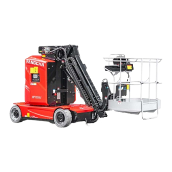
- Page 17 Machine Overview This manual introduces HV series aerial work platform. Users can obtain relevant information such as working height from the product model. Name Description Mast-type Maximum operating height AC drive system...
-
Page 18: Legend Of Machine Structure
Legend of Machine Structure... -
Page 19: Description Of Machine Status
1. Working platform 2. File box 3. Platform control box 4. Weighing component 5. Leveling joint 6. Telescopic jib 7. Jib luffing mechanism 8. Mast head cover 9. Platform valve 10. Fifth-stage sleeve 11. Fourth-stage sleeve 12. Third-stage sleeve 13. Second-stage sleeve 14. -
Page 20: Label
Label Use the following pictures to verify whether the labels on the machine are easy to identify and in the right position. - Page 21 The following table is a list of label descriptions. Name Name Label "Anti-pressure head label" Safety anchor label Label "Word HANGCHA" Label "Anti-pinch label" It is strictly prohibited to change or Type label HV120AJ remove the limit switch label No standing label Risk labels for explosion and fire Label "Word HANGCHA"...
-
Page 22: Product Performance Parameters (For Reference Only)
Product Performance Parameters (for Reference Only) Parameter item Unit HV120AJ Length Width Height 1.98 Ground clearance Ground clearance (to tipping protection plate) Machine weight 5000 Maximum working height Maximum platform height Maximum horizontal extension Maximum crossing height 5.99 Maximum bearing capacity Wheelbase Turning radius of inner wheel 0.75... - Page 23 Working range diagram...
- Page 24 Machine nameplate...
-
Page 25: Controller
Controller Ground controller 1. Multi-function display 2. Emergency stop switch 3. Key switch screen 4. Action direction switch 5. Fence tilt switch 6. Fence rotary switch 7. Turntable rotary switch 8. Jib telescopic switch 9. Jib luffing switch 10. Mast lifting switch 11. - Page 26 3. Key switch - Turn the key switch to the "Platform" icon position on the right, and the platform controller will run; - Turn the key switch to the "OFF" position in the middle, and the machine will be shut down; - Turn the key switch to the "chassis"...
- Page 27 - Toggle the switch 10 upward and hold it, and push the switch 5 upward. Downward luffing - Toggle the switch 10 upward and hold it, and push the switch 5 downward. 10. Mast lifting switch This switch is used for the lifting and lowering actions of the mast. First, turn the key switch to the chassis operation: Luffing upward - Toggle the switch 10 upward and hold it, and push the switch 5 upward.
- Page 28 Platform controller 1. Emergency stop switch 2. Mast lifting switch 3. Jib luffing switch 4. Jib telescopic switch 5. Fence tilt switch 6. Overload alarm lamp 7. Tilt alarm lamp 8. Bypass switch 9. Control handle 10. Horn button 11. Rotary selector switch 12.
- Page 29 3. Jib luffing switch This switch is used for the luffing action of the jib: toggle the switch, and within 8 seconds after the corresponding indicator lights up, press the enable switch on the control handle and then push forward or pull backward the control handle to luff the jib upward or downward.
- Page 30 --Pushing the joystick back and forth corresponds to switching of forward/backward travel and the direction of jib action; pushing the joystick left and right corresponds to the rotation of the turntable and the fence. 10. Horn button When the button is pressed, the horn on the vehicle body will sound immediately to remind nearby personnel to yield.
-
Page 31: Pre-Operational Inspection
Pre-operational Inspection Cannot be operated unless: ☑ You have understood and practiced the rules for safe operation of the machine in this operation manual. 1. Avoid dangerous situations. 2. Always perform pre-operational inspection. Know and understand the pre-operational inspection before proceeding to the next step. 3. - Page 32 Pre-operational Inspection □ Ensure that the manual is complete, legible and stored in the manual box in the platform. □ Ensure that all labels are clear, legible and properly located. See "Label" part. □ Check the hydraulic oil for leakage. Check whether the hydraulic oil level is appropriate. See "Maintenance"...
-
Page 33: Workplace Inspection
Workplace Inspection Cannot be operated unless: ☑ You have understood and practiced the rules for safe operation of the machine in this operation manual. 1. Avoid dangerous situations. 2. Always perform pre-operational inspection. Know and understand the pre-operational inspection before proceeding to the next step. 3. -
Page 34: Function Test
Function Test Cannot be operated unless: ☑ You have understood and practiced the rules for safe operation of the machine in this operation manual. 1. Avoid dangerous situations. 2. Always perform pre-operational inspection. Know and understand the pre-operational inspection before proceeding to the next step. 3. - Page 35 ⊙Result: No DTC shall be displayed on the display screen. Test emergency stop 6. Push the ground red emergency stop button inward to the "OFF" position. ⊙ Result: No function is available. 7. Pull out the red emergency stop button on the ground to the "ON" position, and turn the red emergency stop button on the platform clockwise to the "ON"...
- Page 36 12. Press and hold the turntable slewing function enable switch, and toggle the action selection switch up and down. ⊙ Result: The turntable slewing function works and the buzzer sounds at the same time. 13. Press and hold the fence rotation function enable switch, and toggle the action selection switch up and down.
- Page 37 24. Toggle the jib luffing action switch, press and hold the release switch, and slowly move the control handle. ⊙Result: The jib is lowered or raised and the buzzer sounds. 25. Toggle the jib telescoping action switch, press and hold the release switch and slowly move the control handle.
- Page 38 Test limited drive speed 36. Toggle the mast lift/lower selector switch. 37. Press and hold the release switch on the control handle to raise the mast approximately 20 cm. 38. Toggle the travel selector switch. 39. Press and hold the release switch on the control handle, and slowly move the control handle to the maximum opening.
- Page 39 Operating Instructions Cannot be operated unless: ☑ You have understood and practiced the rules for safe operation of the machine in this operation manual. 1. Avoid dangerous situations. 2. Always perform pre-operational inspection. Know and understand the pre-operational inspection before proceeding to the next step. 3.
- Page 40 The machine is designed with a manual emergency lowering feature that allows the machine to return to the ground safely even when the battery is turned off. Mast lowering 3. Pull up on the mast's emergency descent handle to lower the mast to the ground. Be aware of the risk of jamming the jib as the handle is located directly under the jib.
- Page 41 Driving on a slope Determine the slope and side slope ratings and grade of the machine. Maximum ramp rating, retracted position 30% Maximum side slope rating, retracted position 10% Note: The ramp rating is limited by ground conditions and traction. Press the drive speed selection button to select fast drive speed mode.
- Page 42 Charge the battery with the correct AC input voltage as indicated on the charger. ☑ Only batteries and chargers approved by Hangcha can be used. The machine is equipped with a Hangcha lithium battery pack as a standard feature, and maintenance-free lead-acid batteries and lead-acid traction batteries are available as options.
- Page 43 Do not apply any external force to the battery pack or allow it to fall from a great height. Used batteries can be hazardous to humans and the environment. Please comply with workplace and local regulations when disposing of lithium batteries. The lithium battery has an automatic protection function.
- Page 44 9. Disconnect the charger plug from the AC power supply. 10. Close and lock the housing. 11. Pull the red emergency stop switch to the ON position.
- Page 45 Transportation and Lifting Instructions Regulations to be followed: ☑Use good judgment and a plan to control the movement of the machine when lifting it with a crane. ☑Only personnel qualified for overhead lifting should load and unload the machine. ☑Park the transport vehicle on level ground. ☑Secure the transport vehicle against movement when loading the machine.
- Page 46 Lift the machine with a forklift Make sure the controller and housing are securely fastened. Remove all moving parts from the machine. Lower the platform completely. Keep the platform folded during transport. Place the forklift tine in the correct position. Drive forward and insert the forks fully into the notches.
- Page 47 Long-term storage instructions Machines that have not been used for a long time should be stored properly. The ambient temperature should be within the range of -20° C ~ 40° C. Ambient humidity ≤90%. 1. If the machine is parked indoors, select a firm and level surface; if parked outdoors, cover the machine with a dust cloth to prevent rainwater and dust from entering.
-
Page 48: Maintenance
Maintenance Filter element Name Material No. Replacement cycle Oil return filter GTHZ120-6000002-G00 150 hours Filter element GTHZ120-6000003-G00 600 hours Lubricant Lubrication equipment Capacity Recommended specification Hydraulic oil tank L-HM32 hydraulic oil Travel reducer 0.8L each A80W90 Slewing bearing Moderately MALLEUS GL205 Boom slider Moderately High-temperature resistant... - Page 49 Maintenance symbol legend The following symbols are used throughout this Manual to indicate the meaning of the instructions. The meaning is as follows when one or more symbols appear before a maintenance procedure. Indicates that the operation requires a tool. Indicates that the operation requires a new part.
- Page 50 The equipment must be repaired in accordance with the manufacturer's specifications by a qualified service technician. Maintenance inspections must be performed by certified technicians in accordance with the manufacturer's specifications and the requirements of this Manual. Description Use the operation manual provided with the equipment. Pre-delivery preparation consists of operational inspection, maintenance items and functional testing.
- Page 51 Signature of inspector Title of inspector Inspection company Description ▪Use one report for each inspection. ▪Select the appropriate checklist for the inspection item. □Daily or every 8 hours □ Quarterly or every 250 □ Semi-annually or every 500 A + B + C hours □...
- Page 52 B-9 Driving speed in retracted state B-10 Driving speed in lifting state B-11 Working indicator B-12 Running alarm B-13 Hydraulic oil analysis B-14 Hydraulic oil tank respirator B-15 Tension the lifting chain B-16 Check chain condition Checklist C C-1 Platform overload system C-2 Replace the hydraulic oil filter Checklist D...
- Page 53 4. After use, return the manual to its original position. Tip: If there is a need for replacement of the manual or label, please contact Hangcha or its dealer. Perform pre-operational checks Performing pre-operational checks is critical to ensuring safe operation. The pre-operational check is a visual inspection performed before the machine runs.
- Page 54 30-day maintenance The 30-day maintenance is a one-time maintenance after the first 30 days or 40 hours of machine operation. Continue to check the maintenance items on the list after this step. Perform the following maintenance steps: ▪B-3 Tire and hub...
- Page 55 Steps of Checklist B Check the lead-acid battery This inspection shall be performed every 250 hours or every quarter, whichever comes first. Good battery condition is essential for the performance and operational safety of the machine. Incorrect electrolyte levels and damaged cables or connectors can cause damage to machine parts and dangerous situations.
- Page 56 1. Open the housing. 2. Turn the key switch to the ground control position, pull out the red emergency stop button on the ground to the "ON" position, and turn the red emergency stop button on the platform clockwise to the "ON"...
- Page 57 1. Inspect the tread and sidewall for scratches, cracks, punctures and other abnormal wear. 2. Inspect the hub for damage, bending, and cracking. 3. Check the torque of all bolts Torque of steering wheel 200N· m± 10% Torque of driving wheel 250N·...
- Page 58 Additional equipment is required to perform this procedure. Do not lean the ladder or scaffold against the machine during maintenance. This procedure requires personnel with specific maintenance skills and appropriate tools. Serious injury or death may result if these instructions are not followed. Test the key switch This inspection shall be performed every 250 hours or every quarter, whichever comes first.
- Page 59 Test the driving brake function This inspection shall be performed every 250 hours or every quarter, whichever comes first. Proper braking is critical to operational safety. The brake should operate smoothly without delay, bump, or abnormal noise. There is no difference in the appearance of the wheels before and after the brake is released.
- Page 60 2. Turn the key switch to the platform control, pull out the red emergency stop button on the ground to the "ON" position, and turn the red emergency stop button on the platform clockwise to the "ON" position. 3. Lower the platform to the retracted position. 4.
- Page 61 15. Select a point on the machine (such as the touchdown point on the wheel) as a reference for visually crossing the starting and ending lines. 16. Run the machine to its maximum speed and start timing when the reference point crosses the starting line.
- Page 62 ⊙ Result: The alarm sounds. 7. Press the drive function selection button. 8. Press and hold the function enabling switch, and push the handle back and forth. ⊙ Result: The alarm sounds. 9. Function release switch, press and hold the thumb button on the handle. Result: The alarm sounds.
- Page 63 Check and adjust the lifting chain Keeping the chain in good condition is essential for safe operation and good machine performance. The overall length of the chain will increase as a direct result of chain wear. Visually inspect the used conveyor chain every three months to check for stretching. The mast connected to the long chain will be in a lower position, resulting in uneven tops of each mast when the machine is retracted.
- Page 64 B-16 Check chain condition Keeping the chain in good condition is essential for safe operation and good machine performance. Equipment required: ● Standard toolkit ● Goggles ● Gloves ●Place barriers around the perimeter of the work area Special and auxiliary tools must be used according to regulations. Always wear appropriate safety clothing.
- Page 65 Check to see if the link is twisted, deformed, or damaged. Distortion Cracking Damaged Folded ● Check the connection points of the flights (center lines must be parallel). Replace the chain Chains should be replaced every 7 years. For more opinions and suggestions, please contact Hangcha's After-sales Service Department.
- Page 66 Steps of Checklist C Test platform overload system This inspection shall be performed every 500 hours or 6 months, whichever comes first. Check the machine immediately if it is overloaded. Frequent testing of the platform overload mechanism is very important for the safe operation of the machine.
- Page 67 Replace the hydraulic oil tank filter This inspection shall be performed every 500 hours or semi-annually, whichever comes first. The hydraulic oil tank is equipped with an oil suction strainer at the bottom and a return filter at the top of the tank.
- Page 68 Steps of Checklist D Test or replace hydraulic oil This inspection shall be performed every 1000 hours or once a year, whichever comes first. Hydraulic fluid replacement or testing is essential for good machine performance and service life. Dirty hydraulic oil and suction filters affect machine performance. Continued use can cause damage to parts. Under severe working conditions, this operation should be performed more frequently.
- Page 69 Operation without oil may result in damage to the hydraulic pump. To avoid cavitation in the hydraulic system, pump the oil tank carefully when filling the hydraulic system. Electrical Fault Diagnosis and Troubleshooting If the electrical system fails, the corresponding DTC is displayed on the chassis panel and on the platform joystick screen.
- Page 70 The upper arm luffing selector Remote control switch of the upper control box communication fault fault Telescopic selector switch of Platform overload upper control box fault Leveling selector switch of upper Anti-collision switch fault control box platform fault 1A5 left motor controller Upper control traveling selector fault switch fault...
-
Page 71: Maintenance Record Form
Maintenance Record Form Maintenance Record Form... - Page 72 Maintenance Record Form...
Need help?
Do you have a question about the HV Series and is the answer not in the manual?
Questions and answers