Table of Contents
Advertisement
Quick Links
www.ti.com
EVM User's Guide: TPLD1201-DGS-EVM
TPLD1201-DGS-EVM Evaluation Module
Description
The TPLD1201DGS is part of the TI Programmable
Logic Device (TPLD) family of devices that feature
versatile programmable logic ICs with combinational
logic, sequential logic and mixed-signal functions to
provide an integrated, compact, low power design
to implement common system functions, such as
timing delays, voltage monitors, system resets, power
sequencers, and I/O expanders.
The TPLD1201-DGS-EVM helps users to configure
TPLD1201DGS devices without requiring the
soldering of the devices to the board. Users can
utilize InterConnect Studio (ICS) for fast evaluation,
development, simulation, and programming. Once
programmed, TPLD devices can be removed from the
socket and placed in a user's system.
Get Started
1. Order the TPLD1201-DGS-EVM and TPLD-
PROGRAM
2. Download the latest version of
Studio (ICS)
SCEU030 – AUGUST 2024
Submit Document Feedback
3. Use the cables included the TPLD-PROGRAM kit
4. Place an unprogrammed TPLD1201DGS into the
Features
•
•
•
•
Applications
•
•
•
•
•
•
InterConnect
Copyright © 2024 Texas Instruments Incorporated
to connect the system
socket and configure using ICS
DGS socket for easy programming and evaluation
of TPLD1201DGS
Input buttons, potentiometers, and output LEDs for
quick evaluation
Header pins and test points for interfacing with
custom systems
Interfaces with TPLD-PROGRAM using a standard
keyed 14-pin cable
Factory automation and control
Communications equipment
Retail automation and payment
Test and measurement
Pro audio, video and signage
Personal electronics
TPLD1201-DGS-EVM Evaluation Module
Description
1
Advertisement
Table of Contents

Related Manuals for Texas Instruments TPLD1201-DGS-EVM


Summary of Contents for Texas Instruments TPLD1201-DGS-EVM
- Page 1 Input buttons, potentiometers, and output LEDs for sequencers, and I/O expanders. quick evaluation • Header pins and test points for interfacing with The TPLD1201-DGS-EVM helps users to configure custom systems TPLD1201DGS devices without requiring the • Interfaces with TPLD-PROGRAM using a standard soldering of the devices to the board.
-
Page 2: Kit Contents
EVM, how to use the EVM in conjunction with a TPLD- PROGRAM board, and how to use InterConnect Studio to configure the TPLD1201. Also included are the printed circuit board (PCB) layout, the schematic, and the bill of materials (BOM) of the TPLD1201-DGS-EVM. Note To program devices, the TPLD-PROGRAM board and InterConnect Studio are required. - Page 3 2.1.3 External Connection Header Block The P2 header block is intended to be used to interface the TPLD1201-DGS-EVM with an external system. Using the guide printed on the EVM silkscreen, the TPLD pins can be interfaced with an external system to allow for prototyping and testing in customer systems.
- Page 4 Pin Number IO Name Testing Block Testing Block Name LED/POT LED1/R1 LED/POT LED2/R2 LED/POT LED4/R4 LED5 LED6 LED7 TPLD1201-DGS-EVM Evaluation Module SCEU030 – AUGUST 2024 Submit Document Feedback Copyright © 2024 Texas Instruments Incorporated...
- Page 5 Each LED block consists of an LED that can be connected or disconnected from the TPLD pin via a header. To connect the LED to the corresponding pin, place a shunt on the corresponding header between the two header pins. Figure 2-3. LED Blocks SCEU030 – AUGUST 2024 TPLD1201-DGS-EVM Evaluation Module Submit Document Feedback Copyright © 2024 Texas Instruments Incorporated...
-
Page 6: Switch Blocks
TPLD pin. Note The debounce circuit must not be connected on the GPI pin during programming. Figure 2-4. Switch Blocks TPLD1201-DGS-EVM Evaluation Module SCEU030 – AUGUST 2024 Submit Document Feedback Copyright © 2024 Texas Instruments Incorporated... - Page 7 0.2V. When the POT is turned fully counterclockwise, the analog voltage source outputs at least VCC - 0.2V. Figure 2-5. LED/POT Blocks SCEU030 – AUGUST 2024 TPLD1201-DGS-EVM Evaluation Module Submit Document Feedback Copyright © 2024 Texas Instruments Incorporated...
-
Page 8: Installing Software
For more information on using InterConnect Studio (ICS), reference the InterConnect Studio User's Guide. 3.2 Configuring a TPLD Device This section covers the steps to use the TPLD1201-DGS-EVM and a TPLD-PROGRAM kit to program a TPLD1201DGS. TPLD1201-DGS-EVM Evaluation Module SCEU030 –... - Page 9 Software 3.2.1 TPLD1201-DGS-EVM Setup for Programming Make sure that the following conditions are met: 1. Set SW3 to the ON position. 2. Set the GPI Pin 1jumper (J2) to the OFF position or remove the jumper 3. Remove the EXT_VCC (J1) jumper 4.
- Page 10 2. Connect the TPLD-PROGRAM to the TPLD1201-DGS-EVM using the provided 14-position ribbon cable. Make sure that a good connection is made between the TPLD1201-DGS-EVM and the TPLD-PROGRAM, indicated by the 3V3 LED in the top left of the EVM being on.
- Page 11 TPLD-PROGRAM, then select OK. Figure 3-6. Temporarily Configuring in ICS a. Some LEDs on the TPLD1201-DGS-EVM flash during the programming sequence, which is normal. b. If the configuration fails, check the connections between the EVM and the computer, make sure SW3 is ON, check the connection between the TPLD device and the socket contacts, and retry.
- Page 12 3.3 Testing with the TPLD1201-DGS-EVM Demo This section is intended to be an example on how to use the TPLD1201-DGS-EVM to test a temporarily configured circuit. The TPLD1201 demo is designed to show the key functions of the TPLD1201, such as the internal oscillators, flip-flops, counters, gates, and analog comparators.
- Page 13 GPI input is high, the look-up table outputs high, and when the IO9 input is high, the look-up table outputs low. The output of the look-up table drives the digital output IO5. Figure 3-8. TPLD1201 EVM Demo SCEU030 – AUGUST 2024 TPLD1201-DGS-EVM Evaluation Module Submit Document Feedback Copyright © 2024 Texas Instruments Incorporated...
- Page 14 Set R2 to a middle value, then move R1 to see the trigger of the analog comparator ACMP0, output to LED6. Similarly, R4 can be turned to see the trigger of the analog comparator ACMP1 on LED7. TPLD1201-DGS-EVM Evaluation Module SCEU030 – AUGUST 2024 Submit Document Feedback Copyright © 2024 Texas Instruments Incorporated...
- Page 15 Hardware Design Files 4 Hardware Design Files 4.1 Schematics Figure 4-1. TPLD1201-DGS-EVM Schematic SCEU030 – AUGUST 2024 TPLD1201-DGS-EVM Evaluation Module Submit Document Feedback Copyright © 2024 Texas Instruments Incorporated...
-
Page 16: Pcb Layout
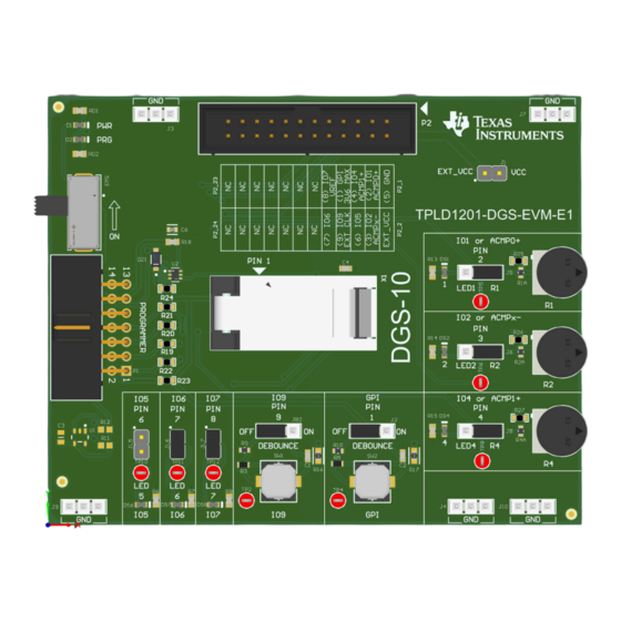
Hardware Design Files www.ti.com 4.2 PCB Layout Figure 4-2. TPLD1201-DGS-EVM Layout 4.2.1 PCB Overview Figure 4-3. TPLD1201-DGS-EVM Board Front TPLD1201-DGS-EVM Evaluation Module SCEU030 – AUGUST 2024 Submit Document Feedback Copyright © 2024 Texas Instruments Incorporated... - Page 17 Hardware Design Files Figure 4-4. TPLD1201-DGS-EVM Board Bottom SCEU030 – AUGUST 2024 TPLD1201-DGS-EVM Evaluation Module Submit Document Feedback Copyright © 2024 Texas Instruments Incorporated...
- Page 18 4.3 Bill of Materials This section provides information on the components that can be used with the TPLD1201-DGS-EVM. Other components can be used as long as the components are able to fit the provided plated holes and pads. Table 4-1. Bill of Materials...
-
Page 19: Additional Information
Additional Information 5 Additional Information 5.1 Trademarks All trademarks are the property of their respective owners. SCEU030 – AUGUST 2024 TPLD1201-DGS-EVM Evaluation Module Submit Document Feedback Copyright © 2024 Texas Instruments Incorporated... - Page 20 STANDARD TERMS FOR EVALUATION MODULES Delivery: TI delivers TI evaluation boards, kits, or modules, including any accompanying demonstration software, components, and/or documentation which may be provided together or separately (collectively, an “EVM” or “EVMs”) to the User (“User”) in accordance with the terms set forth herein.
- Page 21 www.ti.com Regulatory Notices: 3.1 United States 3.1.1 Notice applicable to EVMs not FCC-Approved: FCC NOTICE: This kit is designed to allow product developers to evaluate electronic components, circuitry, or software associated with the kit to determine whether to incorporate such items in a finished product and software developers to write software applications for use with the end product.
- Page 22 www.ti.com Concernant les EVMs avec antennes détachables Conformément à la réglementation d'Industrie Canada, le présent émetteur radio peut fonctionner avec une antenne d'un type et d'un gain maximal (ou inférieur) approuvé pour l'émetteur par Industrie Canada. Dans le but de réduire les risques de brouillage radioélectrique à...
- Page 23 www.ti.com EVM Use Restrictions and Warnings: 4.1 EVMS ARE NOT FOR USE IN FUNCTIONAL SAFETY AND/OR SAFETY CRITICAL EVALUATIONS, INCLUDING BUT NOT LIMITED TO EVALUATIONS OF LIFE SUPPORT APPLICATIONS. 4.2 User must read and apply the user guide and other available documentation provided by TI regarding the EVM prior to handling or using the EVM, including without limitation any warning or restriction notices.
- Page 24 Notwithstanding the foregoing, any judgment may be enforced in any United States or foreign court, and TI may seek injunctive relief in any United States or foreign court. Mailing Address: Texas Instruments, Post Office Box 655303, Dallas, Texas 75265 Copyright © 2023, Texas Instruments Incorporated...
-
Page 25: Important Notice
TI products. TI’s provision of these resources does not expand or otherwise alter TI’s applicable warranties or warranty disclaimers for TI products. TI objects to and rejects any additional or different terms you may have proposed. IMPORTANT NOTICE Mailing Address: Texas Instruments, Post Office Box 655303, Dallas, Texas 75265 Copyright © 2024, Texas Instruments Incorporated...
Need help?
Do you have a question about the TPLD1201-DGS-EVM and is the answer not in the manual?
Questions and answers