Table of Contents
Advertisement
Quick Links
www.ti.com
User's Guide
TPL1401 Evaluation Module
This user's guide describes the characteristics, operation, and use of the TPL1401EVM evaluation module
(EVM). This EVM is designed to evaluate the performance of the
variety of configurations. Throughout this document, the terms evaluation board, evaluation module, and EVM
are synonymous with the TPL1401EVM. This document includes a schematic, reference printed-circuit board
(PCB) layouts, and a complete bill of materials.
SNAU257 – OCTOBER 2020
Submit Document Feedback
ABSTRACT
Copyright © 2020 Texas Instruments Incorporated
TPL1401
buffered voltage output DAC in a
TPL1401 Evaluation Module
1
Advertisement
Table of Contents

Related Manuals for Texas Instruments TPL1401


Summary of Contents for Texas Instruments TPL1401
- Page 1 Throughout this document, the terms evaluation board, evaluation module, and EVM are synonymous with the TPL1401EVM. This document includes a schematic, reference printed-circuit board (PCB) layouts, and a complete bill of materials. SNAU257 – OCTOBER 2020 TPL1401 Evaluation Module Submit Document Feedback Copyright © 2020 Texas Instruments Incorporated...
-
Page 2: Table Of Contents
Table of Contents www.ti.com Table of Contents Overview....................................4 1.1 Kit Contents..................................4 1.2 Related Documentation from Texas Instruments....................... 2 System Setup..................................2.1 Software Setup...................................5 2.2 Hardware Setup................................. 3 Detailed Description................................3.1 Hardware Description...............................10 3.2 Software Description................................ 4 Schematic, PCB Layout, and Bill of Materials........................ - Page 3 Table 4-1. BOOSTXL-DAC-PORT Bill of Materials........................28 Table 4-2. TPL1401EVM Bill of Materials..........................Trademarks Launchpad ™ is a trademark of Texas Instruments. Microsoft ® and Windows ® are registered trademarks of Microsoft Corporation. All other trademarks are the property of their respective owners.
-
Page 4: Overview
This device supports I2C standard mode, fast mode, and fast+ mode. The TPL1401 provides the FB pin to configure the output as a programmable current sink using an external MOSFET. The TPL1401 is simple to program using an I2C interface at factory or in real-time. An integrated nonvolatile memory (NVM) enables factory programming for trimming and calibration applications. -
Page 5: System Setup
Figure 2-1. When the TPL1401EVM software is launched, an installation dialog window opens and prompts the user to select an installation directory. If left unchanged, the software location defaults to C:\Program Files (x86)\Texas Instruments\TPL1401 EVM as shown in Figure 2-2. -
Page 6: Figure 2-2. Software Installation Path
5. If the GUI Composer framework is being installed for the first time on the PC, the browser extension and the TI Cloud Agent must be installed. Follow the 2-step installation flow prompted on the web page, as shown in Figure 2-3 TPL1401 Evaluation Module SNAU257 – OCTOBER 2020 Submit Document Feedback Copyright © 2020 Texas Instruments Incorporated... -
Page 7: Figure 2-3. Ti Cloud Agent Installation
7. Press Start and browse for <Download Directory>\TPL1401EVM_1.0.1_installer_win \install_image_TPL1401EVM.\TPL1401EVM\firmware\acctrl.0.3.0.3b.bin. Press Load Image followed by Verify Image. Remove Jumper Mount Jumper Figure 2-4. Analog EVM Controller Setup SNAU257 – OCTOBER 2020 TPL1401 Evaluation Module Submit Document Feedback Copyright © 2020 Texas Instruments Incorporated... -
Page 8: Hardware Setup
1.8 V to 3.6 V (3.3 V Available on Analog EVM Controller), Jumper J10.1-2 on BOOSTXL-DAC-PORT J1.7 DAC_VIO 1.8 V to 3.6 V, Jumper J11.1-2 on BOOSTXL-DAC-PORT J1.1 TPL1401 Evaluation Module SNAU257 – OCTOBER 2020 Submit Document Feedback Copyright © 2020 Texas Instruments Incorporated... -
Page 9: Figure 2-6. Hardware Setup Guidelines
Observe proper ESD handling precautions when unpacking and handling the EVM, including the use of a grounded wrist strap at an approved ESD workstation. SNAU257 – OCTOBER 2020 TPL1401 Evaluation Module Submit Document Feedback Copyright © 2020 Texas Instruments Incorporated... -
Page 10: Detailed Description
SPI/GPIO Digital Level Translator C Level Translator 5 V / 3.3 V Analog and Power Supply Function Extender Figure 3-1. BOOSTXL-DAC-PORT Hardware Block Diagram TPL1401 Evaluation Module SNAU257 – OCTOBER 2020 Submit Document Feedback Copyright © 2020 Texas Instruments Incorporated... -
Page 11: Table 3-1. Boostxl-Dac-Port J13 Pin
5-V power supply Ground GPIO General-purpose I/O GPIO General-purpose I/O VDD_SENSE Sense Input for VDD VIO_SENSE Sense Input for VIO GPIO General-purpose I/O GPIO General-purpose I/O SNAU257 – OCTOBER 2020 TPL1401 Evaluation Module Submit Document Feedback Copyright © 2020 Texas Instruments Incorporated... -
Page 12: Table 3-3. Boostxl-Dac-Port J4 Pin Definitions
Analog I/O AIO13 Analog I/O AGND Analog Ground AIO15 Analog I/O REFGND External Reference Ground Ground VSS Output VIO or DAC_VIO VIO or DAC_VIO Output TPL1401 Evaluation Module SNAU257 – OCTOBER 2020 Submit Document Feedback Copyright © 2020 Texas Instruments Incorporated... -
Page 13: Table 3-5. Boostxl-Dac-Port J12 Pin Definitions
Table 3-5. BOOSTXL-DAC-PORT J12 Pin Definitions Pin# Signal Description High-voltage positive power supply High-voltage negative power supply Ground EXT_VDD External VDD EXT_VIO External VIO SNAU257 – OCTOBER 2020 TPL1401 Evaluation Module Submit Document Feedback Copyright © 2020 Texas Instruments Incorporated... -
Page 14: Figure 3-2. Tpl1401Evm Hardware Block Diagram
PORT with two 16-pin connectors. These headers provide access to all DAC pins. The EVM board also houses an EEPROM and an I C buffer. Figure 3-2. TPL1401EVM Hardware Block Diagram TPL1401 Evaluation Module SNAU257 – OCTOBER 2020 Submit Document Feedback Copyright © 2020 Texas Instruments Incorporated... -
Page 15: Table 3-6. Tpl1401Evm J2 Pin Definitions
Power supply for EEPROM Not connected Not connected Not connected LDO_CAP LDO bypass capacitor AGND Analog ground AGND Analog ground AGND Analog ground AGND Analog ground SNAU257 – OCTOBER 2020 TPL1401 Evaluation Module Submit Document Feedback Copyright © 2020 Texas Instruments Incorporated... -
Page 16: Software Description
The software provides basic control of all the registers and functions to the TPL1401 device. 3.2.1 Starting the Software To launch the software, locate the Texas Instruments folder in the All Programs menu, and select the TPL1401 EVM icon. Figure 3-3. TPL1401EVM GUI Location TPL1401 Evaluation Module SNAU257 –... -
Page 17: Figure 3-4. Tpl1401Evm Gui Connection Detection
Options → Serial Port, and change the port to the other available port with the (Texas Instruments) or ACCtrl tag. Out of the two ports with these tags, one port should connect. Figure 3-4. TPL1401EVM GUI Connection Detection 3.2.2 Software Features... -
Page 18: Figure 3-6. Tpl1401Evm Setup Page
Controller, and details how the Analog EVM Controller, BOOSTXL-DAC-PORT, and TPL1401EVM are stacked. This page also shows the default jumper settings for the BOOSTXL-DAC-PORT. Figure 3-6. TPL1401EVM Setup Page TPL1401 Evaluation Module SNAU257 – OCTOBER 2020 Submit Document Feedback Copyright © 2020 Texas Instruments Incorporated... -
Page 19: Figure 3-7. Tpl1401Evm Quick-Start Page : Basic Dpot Configuration
Figure 3-7 shows the Basic DPOT setup tab that provides an interface to quickly power up, select the reference and output span, and program the output voltage (decimal) for the TPL1401. The TPL1401 comes in Hi-Z power- down mode by default. -
Page 20: Figure 3-8. Register Map Page
3-8, allows the user to access low level communication directly with the TPL1401 registers. Selecting a register on the Register Map list shows a description of the values in that register, as well as information on the register address, default value, size, and current value. -
Page 21: Schematic, Pcb Layout, And Bill Of Materials
Detailed Description 3.2.2.5 Collateral Page Figure 3-10 shows the page that provides links for all the collateral on the TPL1401 device. Figure 3-10. Collateral Page 4 Schematic, PCB Layout, and Bill of Materials This section contains the complete bill of materials and schematic diagram for the BOOSTXL-DAC-PORT and TPL1401EVM. -
Page 22: Boostxl-Dac-Port Schematic
This assumes that the BO board has another buffer to isolate the EEPROM signals from the DAC (VCC-VSS)-max = 43V unless DAC_VIO is present VIO Selection Figure 4-1. BOOSTXL-DAC-PORT Schematic Page 1 TPL1401 Evaluation Module SNAU257 – OCTOBER 2020 Submit Document Feedback Copyright © 2020 Texas Instruments Incorporated... -
Page 23: Figure 4-2. Boostxl-Dac-Port Schematic
VDD can either be used directly 1.0k sides similar to LP connectors or through an optional voltage divider 0.1uF Figure 4-2. BOOSTXL-DAC-PORT Schematic Page 2 SNAU257 – OCTOBER 2020 TPL1401 Evaluation Module Submit Document Feedback Copyright © 2020 Texas Instruments Incorporated... -
Page 24: Tpl1401Evm Schematic
Schematic, PCB Layout, and Bill of Materials www.ti.com 4.2 TPL1401EVM Schematic Figure 4-3 shows the TPL1401EVM schematic. Figure 4-3. TPL1401EVM Schematic TPL1401 Evaluation Module SNAU257 – OCTOBER 2020 Submit Document Feedback Copyright © 2020 Texas Instruments Incorporated... -
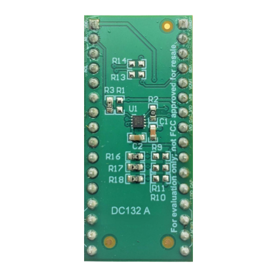
Page 25: Pcb Components Layout
Figure 4-8 show the layout of the components for the TPL1401EVM board. Figure 4-4. BOOSTXL-DAC-PORT PCB Components Layout Figure 4-5. BOOSTXL-DAC-PORT Top Layer SNAU257 – OCTOBER 2020 TPL1401 Evaluation Module Submit Document Feedback Copyright © 2020 Texas Instruments Incorporated... -
Page 26: Figure 4-6. Boostxl-Dac-Port Bottom Layer
Schematic, PCB Layout, and Bill of Materials www.ti.com Figure 4-6. BOOSTXL-DAC-PORT Bottom Layer Figure 4-7. TPL1401EVM PCB Components Layout TPL1401 Evaluation Module SNAU257 – OCTOBER 2020 Submit Document Feedback Copyright © 2020 Texas Instruments Incorporated... -
Page 27: Figure 4-8. Tpl1401Evm Layers
Schematic, PCB Layout, and Bill of Materials Figure 4-8. TPL1401EVM Layers SNAU257 – OCTOBER 2020 TPL1401 Evaluation Module Submit Document Feedback Copyright © 2020 Texas Instruments Incorporated... -
Page 28: Boostxl-Dac-Port Bill Of Materials
RES, 4.99 k, 1%, 0.1 W, 0603 0603 CR0603-FX-4991ELF Bourns R14, R31, R34, R47 RES, 0, 5%, 0.1 W, 0603 0603 RC0603JR-070RL Yageo America TPL1401 Evaluation Module SNAU257 – OCTOBER 2020 Submit Document Feedback Copyright © 2020 Texas Instruments Incorporated... - Page 29 RES, 0, 5%, 0.1 W, 0603 0603 RC0603JR-070RL Yageo America R40, R44 RES, 33, 5%, 0.1 W, AEC-Q200 Grade 0, 0603 CRCW060333R0JNEA Vishay-Dale 0603 SNAU257 – OCTOBER 2020 TPL1401 Evaluation Module Submit Document Feedback Copyright © 2020 Texas Instruments Incorporated...
-
Page 30: Tpl1401Evm Bill Of Materials
RES, 0, 5%, 0.1 W, 0603 0603 RC0603JR-070RL Yageo America R9, R10, R11, R12 10.0k RES, 10.0 k, 1%, 0.1 W, 0603 0603 RC0603FR-0710KL Yageo America TPL1401 Evaluation Module SNAU257 – OCTOBER 2020 Submit Document Feedback Copyright © 2020 Texas Instruments Incorporated... - Page 31 STANDARD TERMS FOR EVALUATION MODULES Delivery: TI delivers TI evaluation boards, kits, or modules, including any accompanying demonstration software, components, and/or documentation which may be provided together or separately (collectively, an “EVM” or “EVMs”) to the User (“User”) in accordance with the terms set forth herein.
- Page 32 www.ti.com Regulatory Notices: 3.1 United States 3.1.1 Notice applicable to EVMs not FCC-Approved: FCC NOTICE: This kit is designed to allow product developers to evaluate electronic components, circuitry, or software associated with the kit to determine whether to incorporate such items in a finished product and software developers to write software applications for use with the end product.
- Page 33 www.ti.com Concernant les EVMs avec antennes détachables Conformément à la réglementation d'Industrie Canada, le présent émetteur radio peut fonctionner avec une antenne d'un type et d'un gain maximal (ou inférieur) approuvé pour l'émetteur par Industrie Canada. Dans le but de réduire les risques de brouillage radioélectrique à...
- Page 34 www.ti.com EVM Use Restrictions and Warnings: 4.1 EVMS ARE NOT FOR USE IN FUNCTIONAL SAFETY AND/OR SAFETY CRITICAL EVALUATIONS, INCLUDING BUT NOT LIMITED TO EVALUATIONS OF LIFE SUPPORT APPLICATIONS. 4.2 User must read and apply the user guide and other available documentation provided by TI regarding the EVM prior to handling or using the EVM, including without limitation any warning or restriction notices.
- Page 35 Notwithstanding the foregoing, any judgment may be enforced in any United States or foreign court, and TI may seek injunctive relief in any United States or foreign court. Mailing Address: Texas Instruments, Post Office Box 655303, Dallas, Texas 75265 Copyright © 2019, Texas Instruments Incorporated...
- Page 36 TI products. TI’s provision of these resources does not expand or otherwise alter TI’s applicable warranties or warranty disclaimers for TI products. Mailing Address: Texas Instruments, Post Office Box 655303, Dallas, Texas 75265 Copyright © 2020, Texas Instruments Incorporated...
Need help?
Do you have a question about the TPL1401 and is the answer not in the manual?
Questions and answers