Sign In
Upload
Manuals
Brands
Allied Telesis Manuals
Switch
GS980EM Series
Allied Telesis GS980EM Series Manuals
Manuals and User Guides for Allied Telesis GS980EM Series. We have
1
Allied Telesis GS980EM Series manual available for free PDF download: Installation Manual
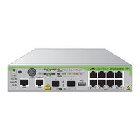
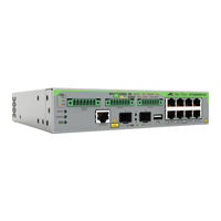
Allied Telesis GS980EM Series Installation Manual (124 pages)
Gigabit Layer 3+ Ethernet Switches with External Power Supply Unit
Brand:
Allied Telesis
| Category:
Switch
| Size: 5.17 MB
Table of Contents
Table of Contents
7
Preface
13
Safety Symbols Used in this Document
14
Contacting Allied Telesis
15
Chapter 1: Overview of the GS980EM/10H Switch
18
Front Panel
18
Figure 1: Front Panel of the GS980EM/10H Switch
18
Features
19
Ports 1 to 8
19
Poe+ Budgets
19
Ports 9 and 10
19
Additional Features
19
Table 1: Maximum Poe Ports Supported on the GS980EM/10H Switch
19
Installation Options
20
Management Methods
20
USB Port
20
Ports 1 to 8
21
Specifications
21
Table 2: Specifications for Ports 1 to 8 on the GS980EM/10H Switch
21
Powered Device Classes
22
Ports 1 to 8 Leds
22
Figure 2: Leds for Ports 1 to 8 on the GS980EM/10H Switch
22
Table 3: Supported Powered Device Classes on Ports 1 to 8 of the GS980EM/10H Switch
22
Table 4: Leds for Ports 1 to 8 on the GS980EM/10H Switch
23
Cable Requirements
24
PWR300 Power Supply
25
Power Supply Unit LED
25
Figure 3: PWR300 Power Supply
25
Table 5: Fault and Power LEDS
25
Poe Port Priorities
26
Table 6: Denial of Ports by Priority
27
SFP Transceiver Ports
29
SFP Transceivers
29
Leds
29
Figure 4: SFP Transceiver Ports Leds
29
Table 7: LEDS for the SFP Transceiver Ports
29
USB Port
30
USB Port LED
30
Figure 5: GS980EM/10H USB Port and LED
30
Table 8: USB LED
30
Console Port
31
Fault and Power Leds
32
Switch Leds
32
Figure 6: Fault and Power Leds
32
Table 9: Fault and Power LEDS
32
Eco-Friendly Command
33
Planning the Installation
34
Table 10: Port 1 to 8 Worksheet for the GS980EM/10H Switch
34
Table 11: Worksheet Column Descriptions
35
Table 12: Power Worksheet for the GS980EM/10H Switch
36
Chapter 2: Beginning the Installation
37
Reviewing Safety Precautions
38
Choosing a Site for the Device
43
Unpacking the Equipment
45
GS980EM/10H Switch
45
Figure 7: GS980EM/10H Shipping Box
45
PWR300 Power Supply
46
Figure 8: PWR300 Shipping Box
46
Accessory Kits
47
GS980EM/10H Switch Accessory Kit
47
Figure 9: GS980EM/10H Switch Accessory Kit
47
19-Inch Rack Mount Kit
48
Figure 10: Rack Mount Kit
48
PWR300 Power Supply Accessory Kit
49
Figure 11: PWR300 Power Supply Accessory Kit
49
RKMT-J24 Wall Mount Kit
50
Figure 12: RKMT-J24 Wall Mount Kit
50
DRMT-J03 DIN Rail Mount Kit
51
RKMT-J15 Tray Bracket Mount Kit
51
Figure 13: DRMT-J03 DIN Rail Mount Kit
51
Figure 14: RKMT-J15 Tray Bracket Mount Kit
51
Chapter 3: Installing the Device on a Table or Desktop
53
Planning the Installation
54
Figure 15: Required Minimum Distances between Devices for a Desk or Table Installation
54
Installing the Switch on a Table or Desktop
55
Figure 16: Affixing the Adhesive Feet
55
Chapter 4: Installing the Device in an Equipment Rack
57
Overview of Installing the Device in an Equipment Rack
58
Figure 17: Rack Mount Kit Brackets and Device
58
Figure 18: GS980EM/10H Switch and PWR300 Power Supplies in the RKMT-J15 Bracket
59
Installing the Device in an Equipment Rack with the Rack Mount Kit Brackets
60
Required Items for the Rack Mount Kit Brackets
60
Device Orientations in the Equipment Rack
60
Figure 19: Bracket Holes
60
Installing the Device with the Brackets
61
Figure 20: Device Orientation with the Front Panel Facing the Front of the Equipment Rack
61
Figure 21: Attaching the Brackets to the Device
62
Figure 22: Attaching the Brackets to the Device
62
Figure 23: Installing the Device in an Equipment Rack
63
Figure 24: Device Secured in an Equipment Rack
64
Installing the Device in an Equipment Rack with the RKMT-J15 Bracket
65
Required Items for the RKMT-J15 Bracket
65
Installing the Device with the RKMT-J15 Bracket
65
Figure 25: Installing the RKMT-J15 Bracket in the Equipment Rack
66
Figure 26: Loosening the Two Thumbscrews on the Front of the RKMT-J15 Bracket
66
Figure 27: Sliding out the Tray of the RKMT-J15
67
Figure 28: Placing a Device in the RKMT-J15 Bracket
67
Figure 29: Securing the Device to the RKMT-J15 Bracket
68
Figure 30: Sliding in the Bracket Tray
68
Figure 31: Tightening the Two Thumbscrews on the RKMT-J15 Bracket
69
Chapter 5: Installing the Device on the DRMT-J03 DIN Rail
71
Installing the Device on the DRMT-J03 DIN Chassis Bracket
72
Figure 32: DRMT-J03 DIN Chassis Bracket
72
Figure 33: Placing the Device on the DRMT-J03 DIN Chassis Bracket
72
Figure 34: Screwing the Device to the DRMT-J03 DIN Chassis Bracket
73
Installing the Device on a DIN Rail
74
Figure 35: Orientation of the Device on a DIN Rail
74
Figure 36: Pressing down on the Spring-Loaded Lever
74
Figure 37: Installing the Device on a DIN Rail
75
Figure 38: Verifying the DIN Rail Installation
76
Chapter 6: Installing the Device on a Wall
77
Device Orientations on a Wall
78
Figure 39: Positioning the GS980EM/10H Switch on the Wall
78
Figure 40: Positioning the PWR300 Power Supply on the Wall
78
Installation Guidelines
79
Tools and Material
79
Plywood Base for a Wall with Wooden Studs
81
Figure 41: Device on the Wall with a Plywood Base
81
Figure 42: Steps to Installing the Device with a Plywood Base
82
Installing a Plywood Base
83
Installing the Device on a Plywood Base
84
Figure 43: Installing the Wall Brackets on a Switch
85
Figure 44: Installing the Wall Brackets on a Power Supply
85
Figure 45: Securing the Device to the Plywood Base
86
Installing the Device on a Concrete Wall
87
Figure 46: Marking the Locations of the Bracket Holes on a Concrete Wall
88
Figure 47: Installing the Device on a Concrete Wall
89
Chapter 7: Cabling the Networking Ports
91
Cabling Twisted Pair Ports
92
Guidelines to Handling SFP Transceivers
93
Installing SFP Transceivers
94
Figure 48: SFP Ports 9 and 10
94
Figure 49: Installing an SFP Transceiver
95
Figure 50: SFP Transceiver Clicking into Place
95
Figure 51: Positioning the SFP Handle in the Upright Position
96
Figure 52: Connecting a Fiber Optic Cable to an SFP Transceiver
96
Chapter 8: Powering on the Switch
97
Powering on the GS980EM/10H Switch
98
Connecting the PWR300 Power Supply
98
Figure 53: Connecting the External Harness to the GS980EM/10H Switch
98
Powering on the PWR300 Power Supply
99
Figure 54: Connecting the PWR300 Power Supply to the GS980EM/10H Switch
99
Figure 55: Installing the Power Cord Retaining Clip on the PWR300 Power Supply
100
Figure 56: Connecting the AC Power Cord
100
Figure 57: Lowering the Power Cord Retaining Clip
101
Figure 58: Connecting the Power Cord to an AC Power Source
101
Monitoring the Initialization Processes
102
Starting a Local Management Session
103
Verifying the Poe Budget
105
Gs980Em/10H
105
Chapter 9: Troubleshooting
108
GS980EM/10H Switch
108
PWR300 Power Supply
108
Poe++ on Ports 1 to 8
108
Twisted Pair Ports 1 to 8
112
SFP Ports
113
Appendix A: Technical Specifications
115
Physical Specifications
116
Figure 59: PWR300 Dimensions
116
Table 13: Product Dimensions
116
Figure 60: GS980EM/10H Dimensions
117
Table 14: Product Weights
117
Table 15: Ventilation Requirements
117
Environmental Specifications
118
Table 16: Environmental Specifications
118
Table 17: GS980EM/10H + PWR300 Operating Temperature Derating
118
Power Specifications
119
Table 18: Maximum Power Consumptions
119
Table 19: Input Voltages
119
Table 20: Heat Dissipation
119
Certifications
120
Table 21: Product Certifications
120
Twisted Pair Port Pinouts
121
Table 22: Pin Signals for 10 and 100 Mbps
121
Table 23: Pin Signals for 1Gbps
122
Style Serial Console Port Pinouts
123
Table 24: RJ-45 Style Serial Console Port Pin Signals
123
Table 25: GS980EM/10H DC-IN Pin Signals
123
Advertisement
Advertisement
Related Products
Allied Telesis GS980EM/10H
Allied Telesis CentreCOM GS980M Series
Allied Telesis CentreCOM GS980M/52
Allied Telesis CentreCOM GS980M/52PS
Allied Telesis AT GS900/5E
Allied Telesis GS950 PS Series
Allied Telesis CentreCOM GS948MX
Allied Telesis GS950/10PS V2
Allied Telesis CentreCOM GS970EMX/52
Allied Telesis CentreCOM GS970EMX/28
Allied Telesis Categories
Switch
Network Router
Media Converter
Network Hardware
Wireless Access Point
More Allied Telesis Manuals
Login
Sign In
OR
Sign in with Facebook
Sign in with Google
Upload manual
Upload from disk
Upload from URL