Renesas RL78/F14 Series User Manual
Bldc starter kit
Hide thumbs
Also See for RL78/F14 Series:
- User manual (1879 pages) ,
- User manual (58 pages) ,
- User manual (55 pages)
Table of Contents
Advertisement
Quick Links
RL78/F14 BLDC Starter Kit
16
RENESAS MCU
RL78/F14 Series
All information contained in these materials, including products and product specifications,
represents information on the product at the time of publication and is subject to change by
Renesas Electronics Corp. without notice. Please review the latest information published by
Renesas Electronics Corp. through various means, including the Renesas Electronics Corp.
website (http://www.renesas.com).
For updates of the Starter Kit software and documentation please check:
http://www.renesas.eu/update?oc=Y-BLDC-SK-RL78F14
User's Manual: Hardware
Y-BLDC-SK-RL78F14
R20UT3768ED0102 Rev. 1.02
June 20, 2017
Advertisement
Table of Contents

Subscribe to Our Youtube Channel
Related Manuals for Renesas RL78/F14 Series


Summary of Contents for Renesas RL78/F14 Series
- Page 1 All information contained in these materials, including products and product specifications, represents information on the product at the time of publication and is subject to change by Renesas Electronics Corp. without notice. Please review the latest information published by Renesas Electronics Corp. through various means, including the Renesas Electronics Corp.
- Page 2 Renesas Electronics. Renesas Electronics shall not be in any way liable for any damages or losses incurred by you or third parties arising from the use of any Renesas Electronics product for an application categorized as “Specific”...
-
Page 3: Table Of Contents
EEPROM parameters: detailed description ................ 66 Motor Auto-calibration using the PC GUI ................67 Updating the RL78/F14 Flash memory using the Renesas Programming Flash Tool ..80 Communication Protocol between the MCU and the PC GUI ..........84 R20UT3769ED0102 Rev. 1.02... - Page 4 RL78/F14 BLDC Starter Kit User‘s Manual Revision History ........................92 Appendix A: Schematic ....................... 93 R20UT3769ED0102 Rev. 1.02 Page 4 June 20, 2017...
-
Page 5: Introduction
RL78/F14 BLDC Starter Kit User‘s Manual 1. Introduction The Renesas Motor Control starter kit called Y-BLDC-SK-RL78F14, is based on the RL78/F14 device from the powerful 16-bit RL78 microcontroller family with a maximum operating frequency of 32MHz and delivering up to 52DMIPs. - Page 6 RL78/F14 BLDC Starter Kit User‘s Manual Overview of PC Graphical User Interface R20UT3769ED0102 Rev. 1.02 Page 6 June 20, 2017...
- Page 7 RL78/F14 BLDC Starter Kit User‘s Manual CAUTION 1. Do not connect Power Source with more than 3A before loading your Software to the device!!! Otherwise there may be a short circuit trough the FETs. The board can measure up to 17A trough each phase shunt but however as heat dissipation is untested for more than 36W power supply it is not recommended to use a bigger power supply.
-
Page 8: Specifications & Hardware Overview
25.87KB / 2.23KB under IAR and 24.79KB / 2.02KB under CODE SIZE IN FLASH / RAM CS+, including auto/manual PI tuning and Motor identification IAR Embedded Workbench for Renesas RL78 1.40.X TOOL USED, VERSION CS+ for CC V4.00.X COMPILER OPTIMIZATION... - Page 9 To obtain the maximum flexibility, the YBLDCSKRL78F14 kit includes: • A complete on-board 3-phase inverter with a low voltage motor (15V), so it becomes easy to test the powerful sensor less algorithm running on the Renesas 16-bit RL78/F14 microcontroller •...
- Page 10 RL78/F14 BLDC Starter Kit User‘s Manual o On-chip three phase pre-driver circuit PWM control Totem pole type MOSFET gate drive circuit, high drive capability: Ciss = 10000pF Dead time control (adjustable) o On-chip current sense amplifier with reference bias buffer •...
-
Page 11: Connectors Description
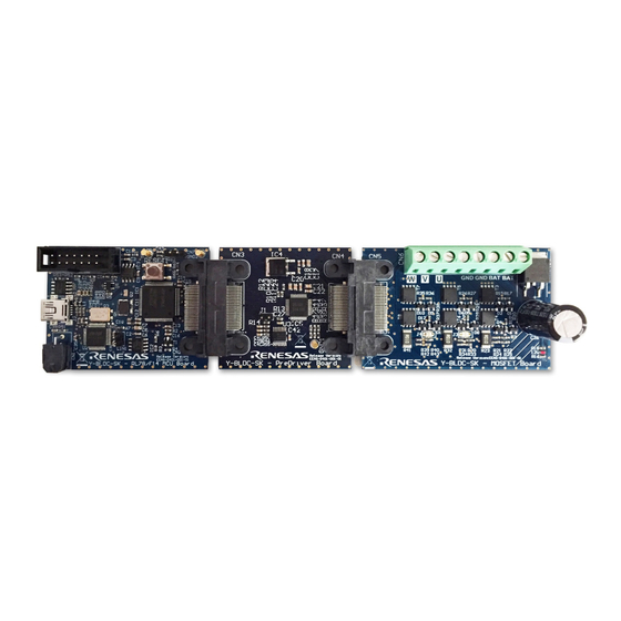
RL78/F14 BLDC Starter Kit User‘s Manual 3. Connectors description As shown in the following figure, you can find the positions and the descriptions of the connectors present on the board. Please refer to the board schematics for the full description of the connectors in Appendix A: Schematic. - Page 12 RL78/F14 BLDC Starter Kit User‘s Manual BOARD CONNECTORS Connectors of RL78/F14 Pre-Driver Board POWER SUPPLY MOTOR CONNECTOR CONNECTOR BOARD CONNECTOR Connectors of RL78/F14 MOSFET Board R20UT3769ED0102 Rev. 1.02 Page 12 June 20, 2017...
-
Page 13: Led Function Description
RL78/F14 BLDC Starter Kit User‘s Manual 4. LED function description The LED available on the board is directly connected to the three phase bus voltage (15V) and allow the user to understand the status of the board, which indicates the presence of the switches drive supply. -
Page 14: Test Points For Debugging
RL78/F14 BLDC Starter Kit User‘s Manual 5. Test points for debugging some microcontroller pins Several specific test points, which connect to , are available on the board to visualize with the oscilloscope the behavior of some internal analog signals. For more details about the test points please refer to Appendix A: Schematic. - Page 15 RL78/F14 BLDC Starter Kit User‘s Manual Test Points of RL78/F14 Pre Driver Board R20UT3769ED0102 Rev. 1.02 Page 15 June 20, 2017...
-
Page 16: Internal Power Board Description
6. Internal power board description The power board is a complete 3-phase bridge composed with discrete low voltage and high current MOSFETs. The MOSFETs are the Renesas NP75N04YUG n-channel power MOSFETs. Please refer to the data-sheet available on the Renesas website: www.renesas.eu... - Page 17 RL78/F14 BLDC Starter Kit User‘s Manual Classical Schema Three Shunts Bridges Furthermore, the intelligent power device R2A25108KFP is adopted to pre-drive the six low voltage MOSFETS NP75N04YUG. R2A25108KFP for Gate-Driver Please find in Appendix A: Schematic the drawing in more details. R20UT3769ED0102 Rev.
-
Page 18: Single Shunt Current Reading
RL78/F14 BLDC Starter Kit User‘s Manual 7. Single shunt current reading While the normal configuration of the board and the standard software are based on three shunts current reading, we also offer the possibility to configure the board for single shunt current reading. -
Page 19: Current Reading Timing In Three Shunts And Single Shunt Configurations
Important Note: The software projects available on the website: http://www.renesas.eu/update?oc=Y-BLDC-SK- RL78F14 are designed under IAR and CS+ for CC environment for three and single shunts configurations. - Page 20 RL78/F14 BLDC Starter Kit User‘s Manual The default value: Shunt R = 10mΩ ; R = 15KΩ; R = 1KΩ. For further information please refer to Appendix A: Schematic. The amplifier circuit shown below is made to manage current up to 14.7A (17A) flowing through the shunts and the output of the amplifier is connected directly to the Microcontroller RL78/F14.
- Page 21 RL78/F14 BLDC Starter Kit User‘s Manual It is mandatory to keep between -2.5V and 2.5V with some margin (margin of 0.3V could be enough) so: -2.2V < Delta_V < 2.2V So the maximum current will be: = 2.2V / (R x (R shunt max dc shunt...
-
Page 22: Microcontroller Rl78/F14 Short Overview
RL78/F14 BLDC Starter Kit User‘s Manual 9. Microcontroller RL78/F14 short overview The RL78/F14 is a high-performance 16-bit microcontroller with a maximum operating frequency of 32MHz and delivers up to 52DMIPS. The RL78/F14 includes hardware support for math calculations, multifunction timers for three phase PWM generation, encoder decoding and general support functions (Timers RD, RG and RJ), event link controller (ELC) for reducing software overhead, a data transfer controller (DTC) for automatic data transfer, 10-bit A/D converter and 8- bit D/A converter, LIN/UART module and CAN interface for network communication. - Page 23 RL78/F14 BLDC Starter Kit User‘s Manual Low-speed on-chip oscillator (LOCO): 15KHz (typ.) Subsystem clock oscillator Other Event link controller (ELC) Option byte Table 2. Main Specifications Overview of Microcontroller RL78/F14 Please find below the RL78/F14 package block diagram. RL78/F14 Package Block Diagram Please find below the memory line-up including the part-names.
- Page 24 RL78/F14 BLDC Starter Kit User‘s Manual Note: To receive a copy of the Hardware Users’ Manual, please contact your local Renesas sales representative. R20UT3769ED0102 Rev. 1.02 Page 24 June 20, 2017...
-
Page 25: Renesas Intelligent Power Device R2A25108Kfp Short Overview
RL78/F14 BLDC Starter Kit User‘s Manual 10. Renesas intelligent power device R2A25108KFP short overview The R2A25108KFP device is an Intelligent Power Device to drive the power MOSFET inverter of the three phase brushless motor. Top View of R2A25108KFP This device contains three set of MOSFET-drivers, charge pump circuit for the gate drive of high... - Page 26 Function for the short to GND protection • Internal oscillation circuit; 175 KHz typ. • 48 pin LQFP package • Comply with AEC-Q100 For further details please refer to the data-sheet available on the Renesas website: www.renesas.eu. R20UT3769ED0102 Rev. 1.02 Page 26 June 20, 2017...
- Page 27 RL78/F14 BLDC Starter Kit User‘s Manual An application example is shown below. R2A25108KFP Application Example R20UT3769ED0102 Rev. 1.02 Page 27 June 20, 2017...
-
Page 28: Permanent Magnets Brushless Motor Model
RL78/F14 BLDC Starter Kit User‘s Manual 11. Permanent Magnets Brushless Motor model The synchronous permanent magnets motor (sinusoidal brushless motor) is widely used in the industry. More and more home appliance makers are now using such brushless motor, mainly because of the intrinsic motor efficiency. The permanent magnet motor is made with few components: •... - Page 29 RL78/F14 BLDC Starter Kit User‘s Manual Let’s analyze the motor from a mathematic point of view. If we apply three voltages v (t), v (t), v (t) to the stator windings, the relations between phase voltages and currents are: λ λ...
- Page 30 RL78/F14 BLDC Starter Kit User‘s Manual The contribution of the permanent magnets in the flux linkages depends on the relative position of the rotor and the stator, represented by the mechanical-electric angleϑ. It is, in every axis, the projection of the constant flux vector Λ in the direction of the axis: λ...
- Page 31 RL78/F14 BLDC Starter Kit User‘s Manual Finally, we obtain for the voltages in (α,β) system: ωλ α − α α β β ωλ β β α A second reference frame is used to represent the equations as the frame is turning at the rotor speed.
- Page 32 RL78/F14 BLDC Starter Kit User‘s Manual 1/(R+sL) Lω τ load τ ω 1/(R+sL) (3/2)pΛ 1/(B+sJ) Λω pΛ the Mathematical Motor Model A control algorithm which wants to produce determined currents in the (d, q) system must impose voltages given from the formulas above. This is ensured by closed loop PI control on both axis “d”...
- Page 33 RL78/F14 BLDC Starter Kit User‘s Manual These equations show that magnetic flux can be obtained from applied voltages and measured currents simply by integration: ∫ λ λ − α α α α ∫ λ λ − β β β β Furthermore: ϑ...
-
Page 34: Sensor Less Field Oriented Control Algorithm
RL78/F14 BLDC Starter Kit User‘s Manual 12. Sensor less Field Oriented Control algorithm Please, find below the sensor less vector control algorithm block diagram. (α, β) (d, q) Vα → → Id PI 0 [Id Vβ Motor (α, β) Modulation (u, v, w) ω... -
Page 35: Software Tools Used
13.1 IAR Embedded Workbench IDE 13.1.1 IAR Embedded Workbench Usage The software was designed under IAR Embedded Workbench for Renesas RL78 Version: 1.40.6. Product Version of IAR Embedded Workspace for Renesas RL78 Product Version of IAR Embedded Workspace for Renesas RL78 The device selected in the program is: RL78/F14-R5F10PMJ, it means the RL78/F14 with 256KB flash, 20KB RAM in an 80-pin package. -
Page 36: Project Importation Into Iar Embedded Workbench
The default location is as follows: Start Menu => All programs => IAR Systems => IAR Embedded Workbench for Renesas RL78 1.40 => IAR Embedded Workbench.exe Click on the “IAR Embedded Workbench.exe” to open, (Note that Windows Vista and 7 users may have to use “Run as administrator”) and the opening screen should open as below. - Page 37 RL78/F14 BLDC Starter Kit User‘s Manual Opening Screen of “YBLDCSKRL78F14.eww” IAR Workspace The project should then open in the IAR IDE and should look something like the window above. Here you can see two projects, YBLDCSKRL78F14_32MHz and YBLDCSKRL78F14_24MHz, which means clock source running at 24MHz and 32MHz are both offered. We take the 32MHz one as a sample to introduce.
- Page 38 RL78/F14 BLDC Starter Kit User‘s Manual Select Debugging Interface E1 The next step is to build the project. The necessary settings have been set in the IDE so that it is not necessary to configure or make changes to any of the build options. These can obviously be viewed for reference, just select the “Option”...
- Page 39 RL78/F14 BLDC Starter Kit User‘s Manual Project Build without Errors Launch the IAR debugger by clicking on the green button on the embedded workbench IDE window. Project Download and Debug Button If the debugger is being used for the first time the emulator needs to be configured before connecting and downloading the code to the board and RL78/F14.
- Page 40 RL78/F14 BLDC Starter Kit User‘s Manual The configuration window will open as shown below. Please check that the settings are as shown in the window below, changing any setting as necessary and then press the “OK” button. Hardware Emulator Setup Window After connection the E1 debugger to the target board powered by USB or external power supply, please click on “Download and...
- Page 41 RL78/F14 BLDC Starter Kit User‘s Manual Debugging Window of Project Other debugging windows can be opened to “watch variables, monitor registers, view the stack, memory etc.” These can be selected by using the “View” menu tab at the top of the workbench and then selecting the required debugging function.
-
Page 42: Cs+ For Cc
RL78/F14 BLDC Starter Kit User‘s Manual Step Reset Step Run to Exit Over (SW and Hardware) Cursor Debugger Stop Next source (Lit when running Step Into statement Hardware) Buttons for Debugging Project under IAR For a full explanation of all debugging options, please use the full documentation included in the IAR installation. -
Page 43: Project Importation Into Cs+ For Cc
RL78/F14 BLDC Starter Kit User‘s Manual The device selected in the program is R5F10PMJ. The compiler used is “Renesas CC-RL”. The debug tool adopted is RL78 E1. Device, Compiler and Debugger selected 13.2.2 Project importation into CS+ for CC The CS+ for CC will have been installed in the default or user location. - Page 44 RL78/F14 BLDC Starter Kit User‘s Manual To open the YBLDCSKRL78F14 CS+ for CC motor control project follow the sequence shown below: File => Open => Sample Application destination folder\YBLDCSKRL78F14\CS+\Three Shunt => Select the file “YBLDCSKRL78F14.mtpj” => Press Open Opening Screen of YBLDCSKRL78F14 under CS+ for CC The project should then open in the CS+ for CC IDE and should look something like the window above.
- Page 45 RL78/F14 BLDC Starter Kit User‘s Manual YBLDCSKRL78F14_32MHz as Active Project” if necessary as shown in the following figure. Set YBLDCSKRL78F14_32MHz as Active Project Please note that depending on settings used previously then the CS+ for CC project windows can look slightly different. All the settings have been pre-set so that the IDE appearance is as constant as possible.
- Page 46 RL78/F14 BLDC Starter Kit User‘s Manual Build Settings in CS+ for CC The project can be built from the build ICON or the rebuild ICON The project should be built without errors as shown in the following figure. R20UT3769ED0102 Rev. 1.02 Page 46 June 20, 2017...
- Page 47 RL78/F14 BLDC Starter Kit User‘s Manual Project Built without Errors Launch the CS+ for CC debugger by clicking on the white button The CS+ for CC debugger will open a progress window which will initially connect to the board and then program the RL78/F14. Once this stage is complete the debugger window will open as shown below.
- Page 48 RL78/F14 BLDC Starter Kit User‘s Manual Debugging Window of Project Other debugging windows can be opened to “watch variables, CPU registers, trace, memory etc.” These can be selected by using the “View” menu tab at the top of the IDE and then selecting the required debugging function.
-
Page 49: Software Description And Resources Used
RL78/F14 BLDC Starter Kit User‘s Manual 14. Software description and Resources used The software delivered in the Y-BLDC-SK-RL78F14 Starter Kit, previously described, is working on the RL78/F14 microcontroller clocked at 32MHz and its operating voltage is 5V which guarantee a high noise immunity. Note: Clock source running at 24MHz and 32MHz are both offered. - Page 50 RL78/F14 BLDC Starter Kit User‘s Manual “PWM_FRE_CUSTOM_HZ”) frequency is set by default to 24 KHz. The parameters are visible in the module name “customize.h”. As the sampling period is 125µs (8KHz), and the control loop for the inverter control takes maximum of 87.5µs under IAR and 78.33µs under CS+, the CPU load of the motor control algorithm with all the option enable is: 87.5/125 = 70% under IAR and 78.33/125 = 62.66% under CS+, where the CPU clock is running at 32MHz.It leaves 30% under IAR and 37.34%...
- Page 51 RL78/F14 BLDC Starter Kit User‘s Manual Main Program EEPROM parameters upload A/D channels offset reading Peripherals initialization Variables initialization Interrupt enabling Main loop synchronization cnt_int == 0 ? cnt_int = NUM_INT Main loop body Speed ramp management Communication management General board management Parameters modification management Flow Chart for the Main Loop in detail R20UT3769ED0102 Rev.
- Page 52 RL78/F14 BLDC Starter Kit User‘s Manual Phase currents (iu , iv ) reading Control Interrupt in three shunts current Transformations (using the phase angle ϑ): reading mode ) → (ia ) → (id , iv , ib , iq Read DC Link voltage v Phase angle update: ϑ...
- Page 53 RL78/F14 BLDC Starter Kit User‘s Manual The auto -tuning process and the self-identification mechanisms are fully independent from the main sensor less vector control software and can be used in the 1 phases of starter and configuration of the software. Features of Auto-Tuning and Motor Self-Identification The three blocks mentioned above and the completed FOC algorithm are located in the library called: “BLDC-SK-Lib_threeShunt”...
- Page 54 Environment IAR V1.xx fdl* RL78 FDL T01 (flash data library) files RENESAS and IAR V2.xx Table 7. Data Flash Library Files of Project Source Code Note: For updates of the data flash library (FDL) please check on the following site: http://www.renesas.eu/update?oc=EEPROM_EMULATION_RL78...
-
Page 55: Start-Up Procedure - Embedded Software
RL78/F14 BLDC Starter Kit User‘s Manual 15. Start-up procedure – Embedded software When the motor is in stand-still, the phase of the permanent magnet flux vector cannot be detected with the used algorithm. So an appropriate start-up procedure has to be applied. The idea is to move the motor in feed-forward (with higher current than that required to win the load), till a speed at which the estimation algorithm can work. - Page 56 RL78/F14 BLDC Starter Kit User‘s Manual to the arbitrary (d ) system are controlled to follow the references by the current PI controllers. On the other hand, since the phase ϑ is still not correctly estimated, id have no physical meaning. Even if they are not shown in the graph, the applied voltages are subjected to the same treatment (vd and vq are calculated in the algorithm).
-
Page 57: Reference System Transformations In Details
RL78/F14 BLDC Starter Kit User‘s Manual 16. Reference system transformations in details Find below the detailed equations used for the coordinates transformations in the embedded software for the RL78/F14 microcontroller. − − α − − β (u, v, w) → (α, β) α... -
Page 58: Rotor Position Estimation
RL78/F14 BLDC Starter Kit User‘s Manual 17. Rotor position estimation The rotor position estimation method which has been chosen is the direct integration of the back EMF. Such method is enabled by default in the RL78/F14 inverter kit. Please find below the fundamental equations: ∫... - Page 59 RL78/F14 BLDC Starter Kit User‘s Manual ω Corresponding S-domain Functions for Filters in Figure 53 It is evident the relationship between Y(s) and the integral I(s)=1/s for s=jω, when ω>>ω In the 2 case, to prevent the integral to diverge, and the errors related to wrong initial conditions are rejected, by the correcting action of the feedback.
- Page 60 RL78/F14 BLDC Starter Kit User‘s Manual The inputs of the system are the imposed voltage vector V and the measured current vector I. The motor phase resistance R , the synchronous inductance L and the permanent magnet flux amplitude λ are known as parameters and motor dependent.
-
Page 61: Pc Graphical User Interface In Details
RL78/F14 BLDC Starter Kit User‘s Manual 18. PC Graphical User Interface in details Please install the Motor Control PC GUI on your machine by following the instructions of the Quick Start Guide delivered in the Y-BLDC-SK-RL78F14 Starter Kit. After connecting the Fulling Motor (FL28BL26-15V-8006AF, 15V , 8000RPM), please connect the board RL78/F14 and select the COM port or use the Auto-detection mechanism. - Page 62 RL78/F14 BLDC Starter Kit User‘s Manual By clicking on the button “Save data to file”, it becomes possible to record regularly all the values display in real-time in a file, as described in figure below: Monitor the recording of Click to record in real-time the values to be stored in All the values and store the “.CSV”...
- Page 63 RL78/F14 BLDC Starter Kit User‘s Manual Alarm code 1: The alarm 1 is called “EEPROM alarm” and described in the software by “EQP_ALL”. This alarm is set when one or more EEPROM parameters are higher than the maximum allowed value or lower than the minimum allowed value.
- Page 64 RL78/F14 BLDC Starter Kit User‘s Manual Question Mark Functions in Parameters Window The detailed description of each parameter is displayed when pointing the mouse on the question mark, see figure above. Each parameters unit is displayed. Note: To change one value in real-time, simply enter the new value and click on “Write” to program the new value into the EEPROM.
- Page 65 RL78/F14 BLDC Starter Kit User‘s Manual All the parameters can be changed on the fly and after pushing the “Write” button, it’s automatically set. Speed range limitations The Y-BLDC-SK-RL78F14 Starter Kit is driving any BLDC using a sensor less vector control algorithm.
-
Page 66: Eeprom Parameters: Detailed Description
RL78/F14 BLDC Starter Kit User‘s Manual 19. EEPROM parameters: detailed description Please find below the software parameters list including their full description. Each parameters located in the “customize.h” header file can be tuned by the user directly by the Graphic User Interface, without re-compiling the program. -
Page 67: Motor Auto-Calibration Using The Pc Gui
RL78/F14 BLDC Starter Kit User‘s Manual 20. Motor Auto-calibration using the PC GUI The full calibration of any 3-phase Brushless DC motor can be performed automatically using the PC Graphical User Interface. Three specific buttons are now available for and shown below: In a few clicks, the software is tuned to the custom motor and ready to run... - Page 68 RL78/F14 BLDC Starter Kit User‘s Manual Specifications of three-phase Brushless DC FL28BL26-15V-8006AF b) Let’s connect the 15VDC Power supply to the YBLDCSKRL78F14 kit. c) Now, connect the USB cable to the PC and the Kit and connect the motor to the kit: Top Overview of RL78/F14 BLDC Starter Kit with Motor R20UT3769ED0102 Rev.
- Page 69 Launch the PC GUI by clicking on the “”Motor Control Demonstration for RL78 F14” ICON on the desktop, or follow these instructions “Start Menu => All programs => Renesas Electronics Europe GmbH => Motor Control Demonstrator for RL78F14 => Motor Control Demonstrator for RL78 F14.exe”.
- Page 70 RL78/F14 BLDC Starter Kit User‘s Manual BOARD RESET Board Reset Button in RL78/F14 BLDC Starter Kit 5) Set the maximum current (parameter n°07) as it will influence all the next steps: Click on “Parameters Setting”, Enter the value: (the unit is in mA) and click on “Write” to save the parameter into the EEPROM and close the parameters setting window.
- Page 71 RL78/F14 BLDC Starter Kit User‘s Manual the embedded software able to generate a step voltage and measuring the motor response. Start Current Auto PI-tuning And click on “Yes” to accept the results to be programed into the EEPROM as shown below. Accept Results of Current Auto PI-tuning Important note: The proportional and integral coefficients are just starter values for the next step “Cu.
- Page 72 RL78/F14 BLDC Starter Kit User‘s Manual h) Now click on the button “Cu. PI tuning” to open the manual current PI tuning window and check the step answer by clicking on “Apply current step” button. Start Step Response Checking the Results of Current Auto PI-tuning Results of Step Response Note: You can manually adjust the value of Kp and Ki, or just slide the slider point to obtain an even better step response and also increase the step current level by increasing the...
- Page 73 RL78/F14 BLDC Starter Kit User‘s Manual Once it’s done, the window can be closed as the proportional and integral coefficients of the PI current are tuned. Perform an auto-identification of the motor parameters by clicking on “Motor Identification” and click “Start”: Start Motor Identification During this process the rotor should start rotating, please leave the rotor free and no loaded.
- Page 74 RL78/F14 BLDC Starter Kit User‘s Manual The stator resistance, the synchronous inductance and the Permanent Magnet flux have been measured and tuned. Important note: • The value above are just starter values, alternately the phase resistance can be found to be sure by measuring the phase-to phase resistance. •...
- Page 75 RL78/F14 BLDC Starter Kit User‘s Manual Speed Control Interface Overview To start the motor, let’s enter a speed which is 1.5 times the minimum speed, in this case 1500 Set the min. Speed in Speed Control Interface m) When the motor is running, you can adjust the two speed PI parameters: the proportional and integral terms: #13 and #14 Please follow the procedure: while running at a medium speed range: 2 times the minimum speed.
- Page 76 RL78/F14 BLDC Starter Kit User‘s Manual Speed PI proportional gain should be tuned in the real application and under load conditions. As starting values, low values should be chosen, they can be increased at medium working speed until instability arises. High frequency instability is related to the proportional value too high, low frequency instability is related to integral value too high.
- Page 77 RL78/F14 BLDC Starter Kit User‘s Manual Start Speed I calibration Set speed to 1000 rpm Set speed to 1000 rpm Set speed to 1500 rpm Speed Reduce I Oscillation Prameter by 1/4 Go to set P Increase I Parameter The Integral Term Tuning Procedure R20UT3769ED0102 Rev.
- Page 78 RL78/F14 BLDC Starter Kit User‘s Manual Start Speed P calibration Set PI parameter to standard value Set speed to 1000 rpm Set Acceleration Ramp to 10kr/s Set speed to 1000 rpm Set speed to Reduce 1500 rpm acceleration ramp Phase current >...
- Page 79 RL78/F14 BLDC Starter Kit User‘s Manual n) Test the parameters found in all the speed ranges and different rotations. o) Finally the parameters list can be saved in a file in .CSV (“Save” button) or .h file (“Create.h” button) format for further use and can also be uploaded later on: Save PC GUI Parameters Troubleshooting: At the stage l) if the motor doesn’t start or generate an alarm n°3, please set the speed to “0”...
-
Page 80: Updating The Rl78/F14 Flash Memory Using The Renesas Programming Flash Tool
The procedure below explains in details how to re-program the RL78/F14 flash memory using the Renesas Flash Programing tool, called the RFP. It could be used to update the RL78/F14 kit with the latest Firmware version downloaded from the website: http://www.renesas.eu/update?oc=Y-... - Page 81 RL78/F14 BLDC Starter Kit User‘s Manual Step1: Open RFP software v3.01.00 select and click on “Create new Project”, select “RL78” in Microcontroller drop down menu, write the project name and browse your project folder. Step 2: Select the E1 in Tool drop down menu in the communication box and make sure in tool details pop window...
- Page 82 RL78/F14 BLDC Starter Kit User‘s Manual Step 3: Browse the file with the “.hex” of your project in the program and then click the large “Start” button Start Updating the Flash Memory using RFP R20UT3769ED0102 Rev. 1.02 Page 82 June 20, 2017...
- Page 83 RL78/F14 BLDC Starter Kit User‘s Manual The RFP will open a progress bar and connect to the board and device. The results of reading from the device should be as shown below. Step 4: At the end of the process “OK” will appear. The new program is now downloaded into the flash of the RL78/F14...
-
Page 84: Communication Protocol Between The Mcu And The Pc Gui
RL78/F14 BLDC Starter Kit User‘s Manual 22. Communication Protocol between the MCU and the PC GUI After the introduction of the auto-tuning, a new set of information is exchanged between the GUI and the board. To distinguish between the software versions the answer to the check request is used. - Page 85 RL78/F14 BLDC Starter Kit User‘s Manual Slave string: l i s o a n D1 .. Dm k = frame total length (1 byte) = slave string identification ('!' = OK answer, '#' = NOK answer) = station address (1 byte) = operation code (1 byte) = data address (1 byte) = data number (1 byte)
- Page 86 RL78/F14 BLDC Starter Kit User‘s Manual 07 Number of bytes in the frame 3F Master string indicator "?" 00 Station address (it is always 0 in our boards) 77 word reading operation "w" 41 data start address (1(address in UIF_R.ram_tab) + 40h (offset to add for ram reading/writing)) 10 number of data (10h=16dec) 39 checksum Board answer:...
- Page 87 RL78/F14 BLDC Starter Kit User‘s Manual 00 MSB of the 7 word of data (UIF_R.ram_tab[7]=UIF_R.var.vb, bus voltage) 18 LSB of the 7 word of data 00 MSB of the 8 word of data (UIF_R.ram_tab[8]) 00 LSB of the 8 word of data 00 MSB of the 9 word of data (UIF_R.ram_tab[9]=UIF_R.var.all, alarm) 01 LSB of the 9...
- Page 88 RL78/F14 BLDC Starter Kit User‘s Manual 57 word writing operation "W" 42 data start address (2(address in UIF_W.ram_tab)+40h(offset to add for ram reading/writing)) 04 number of data 03 MSB of the 1 word of data (value (03E8h=1000dec) to be written in UIF_W.ram_tab[2] = UIF_W.var.rif, speed ref) E8 LSB of the first word of data 00 MSB of the second word of data (value to be written in UIF_W.ram_tab[3], not...
- Page 89 RL78/F14 BLDC Starter Kit User‘s Manual In these cases the address is a < NUM_PAR. To understand in more details the software implementation, please find below the extract of the “userif.h“ module, part of the embedded software. Variables in RAM R20UT3769ED0102 Rev.
- Page 90 RL78/F14 BLDC Starter Kit User‘s Manual Variable Externs Special Working Modes (1) R20UT3769ED0102 Rev. 1.02 Page 90 June 20, 2017...
- Page 91 RL78/F14 BLDC Starter Kit User‘s Manual Special Working Modes(2) R20UT3769ED0102 Rev. 1.02 Page 91 June 20, 2017...
- Page 92 RL78/F14 BLDC Starter Kit User‘s Manual 23. Revision History RL78/F14 BLDC Starter Kit User Manual: Hardware Rev. Date Description Page Summary June 17, 2016 First edition issued June 19, 2017 Corrected description of Figure 53, fix of typing errors June 20, 2017 Revision History completed, fix bug in PDF creation R20UT3769ED0102 Rev.
- Page 93 RL78/F14 BLDC Starter Kit User‘s Manual 24. Appendix A: Schematic R20UT3769ED0102 Rev. 1.02 Page 93 June 20, 2017...
- Page 94 RL78/F14 BLDC Starter Kit User‘s Manual R20UT3769ED0102 Rev. 1.02 Page 94 June 20, 2017...
- Page 95 RL78/F14 BLDC Starter Kit User‘s Manual R20UT3769ED0102 Rev. 1.02 Page 95 June 20, 2017...
- Page 96 RL78/F14 BLDC Starter Kit User‘s Manual R20UT3769ED0102 Rev. 1.02 Page 96 June 20, 2017...
- Page 97 RL78/F14 BLDC Starter Kit User‘s Manual R20UT3769ED0102 Rev. 1.02 Page 97 June 20, 2017...
- Page 98 RL78/F14 BLDC Starter Kit User Manual: Hardware Publication Date: Rev. 1.02 June 20, 2017 Published by: Renesas Electronics Europe...
- Page 99 SALES OFFICES Refer to "http://www.renesas.com/" for the latest and detailed information. Renesas Electronics America Inc. 2880 Scott Boulevard Santa Clara, CA 95050-2554, U.S.A. Tel: +1-408-588-6000, Fax: +1-408-588-6130 Renesas Electronics Canada Limited 1101 Nicholson Road, Newmarket, Ontario L3Y 9C3, Canada...
- Page 100 RL78/F14 BLDC Starter Kit RL78...
- Page 101 Mouser Electronics Authorized Distributor Click to View Pricing, Inventory, Delivery & Lifecycle Information: Renesas Electronics Y-BLDC-SK-RL78F14...
Need help?
Do you have a question about the RL78/F14 Series and is the answer not in the manual?
Questions and answers