Table of Contents
Advertisement
Quick Links
Renesas Solution Starter Kit 12 V Motor Control Evaluation
System for RL78/F24
User's Manual
For Your Safety
Do not fail to read this manual before using the Renesas Solution Starter Kit 12 V Motor Control Evaluation
System for RL78/F24 (RTK7F124FGS00000BJ).
Follow the indications in this manual when using the product.
Keep this manual near the product so you can refer to it whenever necessary.
Transfer or sale of the product to third parties is prohibited without written approval.
The purchaser or importer of the product is responsible for ensuring compliance with local regulations. In
addition, the customer is responsible for ensuring that the product is handled correctly and safely, in
accordance with the laws of the customer's country (region).
All information contained in this manual represents information on products at the time of publication of
this manual. Please note that the product data, specification, sales offices, contents of website, address,
etc., are subject to change by Renesas Electronics Corporation without notice due to product
improvements or other reasons. Please confirm the latest information on Renesas Electronics website.
The manual for the product, and specification (the documents) are the tool that was developed for the
function and performance evaluation of Renesas Electronics semiconductor device (Renesas Electronics
device) mounted on the product, and not guarantee the same quality, function and performance.
By purchasing the product or downloading the documents from Renesas Electronics website, the support
services provided from Renesas Electronics is not guaranteed.
Meaning of Notations
In this manual item related to the safe use of the product are indicated as described below.
The degree of injury to persons or damage to property that could result if the designated content in this manual
is not followed is indicated as follows.
Danger
Warning
Caution
Notes 1. Serious injury refers to conditions resulting in persistent after-effects and for which treatment would
necessitate hospitalization or regular hospital visits, such as loss or impairment of eyesight, burns
(high- or low-temperature), electric shock, bone fracture, or poisoning.
2. Injury refers to conditions for which treatment would necessitate hospitalization or regular hospital
visits.
3. Physical damage refers to damage affecting the wider surroundings, such as the user's home or
property.
R20UT5165EJ0100 Rev.1.00
2022.09.30
Indicates content that, if not followed, could result in death or serious
injury
Note 1
to the user, and which is highly urgent.
Indicates content that, if not followed, could result in death or serious injury
to the user.
Indicates content that, if not followed, could result in injury
Note 3
or physical damage
.
User's Manual
R20UT5165EJ0100
Rev.1.00
2022.09.30
Note 2
to persons
Page 1 of 31
Advertisement
Table of Contents

Related Manuals for Renesas RTK7F124FGS00000BJ


Summary of Contents for Renesas RTK7F124FGS00000BJ
-
Page 1: For Your Safety
User's Manual 2022.09.30 For Your Safety Do not fail to read this manual before using the Renesas Solution Starter Kit 12 V Motor Control Evaluation System for RL78/F24 (RTK7F124FGS00000BJ). Follow the indications in this manual when using the product. - Page 2 12 V Motor Control Evaluation System for RL78/F24 User's Manual Requirements related to the handling of the product are classified into the following categories. • Marks indicating that an action is prohibited. Example: Do Not Touch! General Prohibition Touching the specified location could The indicated action is prohibited.
- Page 3 12 V Motor Control Evaluation System for RL78/F24 User's Manual Warning Items Warning Caution – Rotating Parts! The system includes a motor. Touching the rotating shaft could cause high-temperature burns or injury. Always insert plugs, connectors, and cables securely, and confirm that they are fully inserted. ...
-
Page 4: Introduction
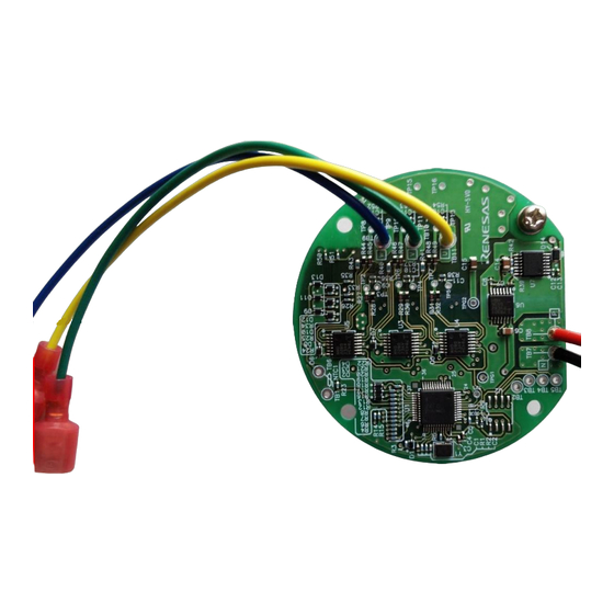
12 V Motor Control Evaluation System for RL78/F24 User's Manual Introduction The product is a brushless DC motor control evaluation kit designed for use in a 12 V automotive power supply environment. The product includes a inverter board with 125 °C compatible automotive grade parts, sample software that runs on the inverter board, and various evaluation data for the system. -
Page 5: Table Of Contents
12 V Motor Control Evaluation System for RL78/F24 User's Manual Contents For Your Safety ..........................1 Introduction ............................. 4 Features ..........................7 Specification Outline ........................ 8 Specification ............................8 Rules and Regulations ..........................9 2.2.1 European Union Regulatory Notices ..................... 9 Block Diagram ........................ - Page 6 12 V Motor Control Evaluation System for RL78/F24 User's Manual 6.1.2 Voltage Generator Circuit ........................22 6.1.3 Connecting the E2/E2 Lite Emulator ....................22 6.1.4 Inverter Control Circuit Block ....................... 23 6.1.5 Current Detection Circuit ........................24 6.1.6 Overcurrent Detection Circuit ......................24 6.1.7 Bus Voltage Detection Circuit ......................
-
Page 7: Features
12 V Motor Control Evaluation System for RL78/F24 User's Manual 1. Features The typical features of this product are shown below. Supports the RL78/F24 microcontroller with the motor control function. Supports permanent magnetic synchronous motors. Supports FOC control method (three-shunt and single-shunt). Supports trapezoidal control method. -
Page 8: Specification Outline
2.1 Specification Table 2-1 12 V Motor Control Evaluation System for RL78/F24 Specifications (1/3) Item Specification Series Renesas Solution Starter Kit 12V Motor Control Evaluation System for RL78/F24 Kit Type RTK7F124FGS00000BJ Kit Contents Inverter Board with RL78/F24 (RTK7F124FGS00000BJ) OCD Conversion Board... -
Page 9: Rules And Regulations
In such cases, the user/operator of the equipment may be required to take appropriate countermeasures under his responsibility. Information for Traceability: Authorised representative Name: Renesas Electronics Corporation Address: Toyosu Foresia, 3-2-24, Toyosu, Koto-ku, Tokyo 135-0061, Japan Manufacture Name: Renesas Electronics Corporation Address: Toyosu Foresia, 3-2-24, Toyosu, Koto-ku, Tokyo 135-0061, Japan ... -
Page 10: Block Diagram
12 V Motor Control Evaluation System for RL78/F24 User's Manual 3. Block Diagram Figure 3-1 shows a block diagram of inverter board with RL78/F24. Inverter Circuit 12V Input Motor Connector Connector +12V Regurator Gate RL78/F24 Driver Port Regurator output 3-phase output A/D input Attenuator... -
Page 11: Layout
12 V Motor Control Evaluation System for RL78/F24 User's Manual 4. Layout Inverter Board: Surface Motor Connection Terminal (TB9, TB10, TB11) Back OCD Connector (To OCD Conversion Board) R20UT5165EJ0100 Rev.1.00 Page 11 of 31 2022.09.30... - Page 12 12 V Motor Control Evaluation System for RL78/F24 User's Manual OCD Conversion Board: Reset switch ICS++ Connector (Optional) OCD Connector OCD Board Connection Terminal (To Inverter Board) (To E2/ E2-Lite Emulator) R20UT5165EJ0100 Rev.1.00 Page 12 of 31 2022.09.30...
-
Page 13: Usage
12 V Motor Control Evaluation System for RL78/F24 User's Manual 5. Usage This chapter describes how to use the 12 V Inverter Board with RL78/F24. 5.1 Quick Start This section describes the quick start procedure for the product. Perform steps (1) to (5) in this order. The product includes a TG-55N-KA permanent magnet synchronous motor manufactured by Tsukasa Electric Co., Ltd (https://www.tsukasa-d.co.jp/). -
Page 14: Connecting The Motor And The Inverter Board Using The Included Motor Cable
12 V Motor Control Evaluation System for RL78/F24 User's Manual 5.1.1 Connecting the Motor and the Inverter Board Using the Included Motor Cable Connect the motor and the motor cable included the product package. Then connect the motor 3-phase wire terminals U, V, and W to the inverter board. -
Page 15: Connecting The Regulated Power Supply And The Inverter Board
12 V Motor Control Evaluation System for RL78/F24 User's Manual 5.1.2 Connecting the Regulated Power Supply and the Inverter Board The product uses ‘Faston terminals’ as connectors for supplying power to the inverter board. Connect the regulated power supply prepared in advance and the power supply cables. The inverter board of the product does not support reverse connection protection circuit. -
Page 16: Software Specification
12 V Motor Control Evaluation System for RL78/F24 User's Manual 5.2 Software Specification As for the state of the product after unpacking, 180-degree energization method three-shunt sensorless vector control software has been written into RL78/F24 microcontroller. The factory-written software specifications are as follows. -
Page 17: Dealing With Errors
Connect inverter board and OCD conversion board with the attached cable. Regulated Power Supply: Output voltage is DC 12 [V], Output current limit is 0.5 [A]. PC (with RFP (Renesas Flash Programmer) installed) Connect E2/E2 Lite emulator and OCD conversion board. -
Page 18: Create The Rfp Project
12 V Motor Control Evaluation System for RL78/F24 User's Manual 5.4.6 Create the RFP Project Select “New project…” in the “File” menu of the RFP. Then set the microcontroller to “RL78/F24”. In this procedure, set the power to “None”. Specify the project name and the project folder. Click "Connect" when the settings are complete. - Page 19 12 V Motor Control Evaluation System for RL78/F24 User's Manual (2) Enabling the PWM Operation Edit the following two places to enabling the PWM operation. File Name : user_control.c (for three-shunt control) Function Name : userControlTimer ( ) Edit “#if 0” to “#if 1”. File Name : user_control.c (for three-shunt control) Function Name : userControlTimer ( ) Edit “#elif 0”...
-
Page 20: Software Specification Of The Pwm Operation Mode
12 V Motor Control Evaluation System for RL78/F24 User's Manual 5.5.2 Software Specification of the PWM Operation Mode The default software specifications of the PWM operation mode (three-shunt) are as follows. Table 5-4 Default Software Specification of the PWM Operation Mode Item Specification Control method... -
Page 21: Board Specification
12 V Motor Control Evaluation System for RL78/F24 User's Manual 6. Board Specification This chapter describes the functions of the inverter board and the OCD conversion board. 6.1 Inverter Board The inverter board included with this product can be equipped with RL78/F24 to operate the permanent magnetic synchronous motor (PMSM). -
Page 22: Voltage Generator Circuit
12 V Motor Control Evaluation System for RL78/F24 User's Manual 6.1.2 Voltage Generator Circuit The inverter bord generates voltages 12 V, 5 V, and 2.5 V from main power supply (from 8 V to 19 V). Table 6-1 Voltage Generator Circuit Input voltage Output voltage Output current... -
Page 23: Inverter Control Circuit Block
12 V Motor Control Evaluation System for RL78/F24 User's Manual 6.1.4 Inverter Control Circuit Block The inverter board has a motor driver circuit block consisting of six N-channel MOS-FETs for motor control. This circuit is equipped with three gate drivers because it is necessary to boost voltage from MCU port outputs for driving N-channel MOS-FETs. -
Page 24: Current Detection Circuit
12 V Motor Control Evaluation System for RL78/F24 User's Manual 6.1.5 Current Detection Circuit The inverter board has current detection circuits to measure the U, V, and W-phase currents (for single-shunt method single-shunt current detection circuit). The U-phase, V-phase, and W-phase are equipped with a shunt resistor forming part of a current detection circuit. -
Page 25: Bus Voltage Detection Circuit
12 V Motor Control Evaluation System for RL78/F24 User's Manual 6.1.7 Bus Voltage Detection Circuit The inverter board has a circuit intended for bus voltage (V ) detection. Input the V to the analog input pin of RL78/F24 via resistive voltage divider. 1 ×... -
Page 26: Motor Coil-End Temperature Detection Circuit
12 V Motor Control Evaluation System for RL78/F24 User's Manual 6.1.9 Motor Coil-end Temperature Detection Circuit The inverter board has a circuit intended for motor coil-end temperature detection. Input to A/D input pin of RL78/F24 using a thermistor externally. This function is optional, and this circuit is not implemented in this product. The default software is designed to support the thermistor (103NT-4-R025H41G). -
Page 27: Ocd Conversion Board
12 V Motor Control Evaluation System for RL78/F24 User's Manual 6.2 OCD Conversion Board This section describes the functions of the OCD conversion board circuit. For details of the circuit, refer to the included circuit diagram. 6.2.1 E2/E2 Lite Emulator Connection The OCD conversion board is used to connect inverter board and E2/E2 Lite emulator. -
Page 28: Usage Notes
12 V Motor Control Evaluation System for RL78/F24 User's Manual 7. Usage Notes Important points to observe when using this product are listed below: • Some of the unused pins the productive not been processed in any way. Make sure to process these pins as appropriate for the application. -
Page 29: Appendix
12 V Motor Control Evaluation System for RL78/F24 User's Manual Appendix The pin assignment table for RL78/F24 product used in this product is shown below. Table A-1 List of RL78/F24 (48 pins) Pin Functions (1/2) Pin Function Functions Used in the Product P120/ANI25/TI07/TO07/TRDIOD0/SO01/(SCK10)/(LTXD1)/INTP4 P41/TI10/TO10/TRJIO0/TRD0RES/(SI10)/(RXD1)/VCOUT0/SNZOUT2 VCOUT0 (connect to INTP0) - Page 30 12 V Motor Control Evaluation System for RL78/F24 User's Manual Table A-1 List of RL78/F24 (48 pins) Pin Functions (2/2) Pin Function Functions Used in the Product P13/TI04/TO04/TRDIOA0/TRDCLK0/SI01/SDA01/LTXD0 P12/TI11/TO11/(TRDIOD0)/SO10/TXD1/INTP5/SNZOUT3 TRDIOD0 (UN-phase) P11/TI12/TO12/(TRDIOB0)/SI10/SDA10/RXD1/CRXD0/LRXD1 TRDIOB0 (UP-phase) P10/TI13/TO13/TRJO0/SCK10/SCL10/CTXD0/LTXD1 P33/AVREFP/ANI6 AVREFP (connect to UVCC) P34/AVREFM/ANI7 AVREFM (connect to GND) P80/ANI0/ANO0...
-
Page 31: Revision History
12 V Motor Control Evaluation System for RL78/F24 User's Manual Revision History Description Rev. Date Page Summary – 1.00 2022.09.30 1st edition issued R20UT5165EJ0100 Rev.1.00 Page 31 of 31 2022.09.30... - Page 32 Unit Products The following usage notes are applicable to all Microprocessing unit and Microcontroller unit products from Renesas. For detailed usage notes on the products covered by this document, refer to the relevant sections of the document as well as any technical updates that have been issued for the products.
- Page 33 Renesas Electronics disclaims any and all liability for any damages or losses incurred by you or any third parties arising from the use of any Renesas Electronics product that is inconsistent with any Renesas Electronics data sheet, user’s manual or other Renesas Electronics document.
Need help?
Do you have a question about the RTK7F124FGS00000BJ and is the answer not in the manual?
Questions and answers