Table of Contents
Advertisement
Quick Links
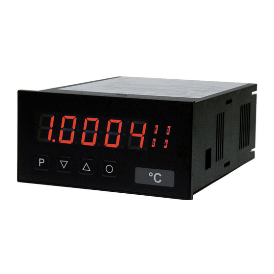
User manual M2-1F
Operating Instructions
Frequency input: 0.01 Hz to 999.99 kHz / 0.01 Hz to 9.9999 kHz / 0-2.500 kHz
Connection for Namur, NPN/PNP with HTL- or TTL-output or for
User manual M2-1F
DAL-111xF00S
position survey via incremental encoder
Frequency input: 0.01 Hz to 999.99 kHz / 0.01 Hz to 9.9999 kHz / 0-2.500 kHz
Frequency input: 0.01 Hz to 999.99 kHz / 0.01 Hz to 9.9999 kHz / 0-2.500 kHz
Connection for Namur, NPN/PNP with HTL- or TTL-output or for
Connection for Namur, NPN/PNP with HTL- or TTL-output or for
position survey via incremental encoder
position survey via incremental encoder
Technical features:
Technical features:
• red display of -19999...99999 digits (optional: green, orange or blue display)
• red display of -19999...99999 digits (optional: green, orange or blue display)
• minimal installation depth: 70 mm without plug-in terminal
• minimal installation depth: 70 mm without plug-in terminal
• min/max memory
• min/max memory
• adjustment via factory default or directly on the sensor signal
• adjustment via factory default or directly on the sensor signal
• 30 adjustable supporting points
• 30 adjustable supporting points
• display flashing at threshold undercut or exceedance
• display flashing at threshold undercut or exceedance
• simplified parameterisation U/min with only 3 parameters
• Schmitt-trigger-input
• simplified parameterisation U/min with only 3 parameters
• zero-key for triggering of Hold, Tara
• Schmitt-trigger-input
• permanent min/max-value recording
• zero-key for triggering of Hold, Tara
• digital frequency filter for contact bounce suppression and interference suppresion
• permanent min/max-value recording
• frequency filter with varying pulse-duty factor
• digital frequency filter for contact bounce suppression and interference suppresion
• volume metering (totaliser) for frequencies up to 1 kHz (accurate to a pulse)
• mathematical function like reciprocal value, square root, rounding
• frequency filter with varying pulse-duty factor
• sliding averaging with an optional dynamic display filter
• volume metering (totaliser) for frequencies up to 1 kHz (accurate to a pulse)
• setpoint generator
• mathematical function like reciprocal value, square root, rounding
• brightness control
• sliding averaging with an optional dynamic display filter
• programming interlock via access code
• setpoint generator
• protection class IP65 at the front
• plug-in terminal
• brightness control
• sensor supply
• programming interlock via access code
• galv. isolated digital input
• protection class IP65 at the front
• option: relay outputs
• plug-in terminal
• option: analog output
• accessories: PC-based configuration-kit PM-TOOL incl. CD & USB-adapter for devices without
• sensor supply
keypad and for a simple adjustment of standard devices
• galv. isolated digital input
• option: relay outputs
M2_1FGB.pdf update: 10.03.2015
• option: analog output
• accessories: PC-based configuration-kit PM-TOOL incl. CD & USB-adapter for devices without
keypad and for a simple adjustment of standard devices
M2_1FGB.pdf update: 10.03.2015
96x48
96x48
Advertisement
Table of Contents

Subscribe to Our Youtube Channel
Related Manuals for ACS contsys DAL-111 F00S Series


Summary of Contents for ACS contsys DAL-111 F00S Series
- Page 1 User manual M2-1F Operating Instructions Frequency input: 0.01 Hz to 999.99 kHz / 0.01 Hz to 9.9999 kHz / 0-2.500 kHz Connection for Namur, NPN/PNP with HTL- or TTL-output or for User manual M2-1F DAL-111xF00S position survey via incremental encoder Frequency input: 0.01 Hz to 999.99 kHz / 0.01 Hz to 9.9999 kHz / 0-2.500 kHz Frequency input: 0.01 Hz to 999.99 kHz / 0.01 Hz to 9.9999 kHz / 0-2.500 kHz Connection for Namur, NPN/PNP with HTL- or TTL-output or for...
- Page 2 Order code power supply 230V AC 10...30V DC galvanic seperated 230V AC with sensor supply 24V DC/50 mA and digital input (no analog output possible) 10...30V DC galvanic seperated with sensor supply 24V DC/ 50 mA and digital input (no analog output possible) function input frequenzy;...
-
Page 3: Table Of Contents
Contents Brief description Assembly Electrical connection Function description and operation 4.1. Programming software PM-TOOL Setting up the device 5.1. Switching on 5.2. Standard parameterisation (flat operation level) Value assignment for the triggering of the signal input 5.3. Programming interlock „RUN“ Activation/Deactivation of the programming interlock or change into professional or flat operation level 5.4. -
Page 4: Brief Description
1. Brief description 1. Brief description The panel meter DAL-111 can evaluate pulses in many different ways and show the result in the 5-digit LED- The panel meter M2-1F can evaluate pulses in many different ways and show the result in the 5-digit LED- display. -
Page 5: Assembly
2. Assembly 2. Assembly Please read the Safety advice on page 36 before installation and keep this user manual for future reference. Gap for physical unit After removing the fixing elements, insert the device. Check the seal to make sure it fits securely. Click the fixing elements back into place and tighten the clamping screws by hand. -
Page 6: Electrical Connection
3. Electrical connection 3. Electrical connection Type DAL-111xF00S Type M2-1FR5B.0307.470CD – supply of 115 VAC Type DAL-111xF00S Type M2-1FR5B.0307.570CD – supply of 230 VAC Type DAL-111xF00S Type M2-1FR5B.0007.670CD – supply of 10-30 VDC galv. isolated Advice: If Namur sensors with a nominal voltage of approx. 8 V are used, then a sensor supply of 12 VDC is needed. For devices with a sensor supply terminals 4 and 8, aswell as terminals 3 and 7 need to be galvanically connected in the device. - Page 7 3. Electrical connection M3-devices Below you find some connection examples with practical applications: ACS-CONTROL-SYSTEM GmbH l Lauterbachstr. 57 l D-84307 Eggenfelden l www.acs-controlsystem.de l info@acs-controlsystem.de...
-
Page 8: Function Description And Operation
4. Function and operation description 4. Function and operation description Operation The operation is divided into three different levels. Menu level (delivery status) This level is for the standard settings of the device. Only menu items which are sufficent to set the device into operation are displayed. -
Page 9: Programming Software Pm-Tool
4. Function and operation description Function chart: 4.1. Parameterisation software PM-TOOL: Part of the PM-TOOL are the software on CD and an USB-cable with device adapter. The connection is done via a 4-pole micromatch-plug on the back side of the device, to the PC-side the connection ist done via an USB plug. -
Page 10: Setting Up The Device
5. Setting up the device 5. Setting up the device 5.1. Switching-on Once the installation is complete, start the device by applying the voltage supply. Before, check once again that all electrical connections are correct. Starting sequence For 1 second during the switching-on process, the segment test (8 8 8 8 8) is displayed, followed by an indication of the software type and, after that, also for 1 second, the software version. - Page 11 5. Setting up the device Menu level Parameterisation level Setting the final value of the measuring range, END: Default: 10000 Set the final value from the smallest to the highest digit with [▲] [▼] and confirm each digit with [P]. A minus sign can only be parameterized on the highest value digit. After the last digit, the display switches back to the menu level.
- Page 12 5. Setting up the device Menu level Parameterisation level Rescaling the measuring input values, OFFA: Default: 0 With this function, you can rescale the input value of e.g. 100 Hz (works setting) without applying a measuring signal. If sensor calibration has been selected, these parameters are not available.
- Page 13 5. Setting up the device Menu level Parameterisation level Setting up the initial value of the analog output, Out.OF: Default: 00000 The final value is adjusted from the smallest digit to the highest digit with [▲] [▼] and digit by digit confirmed with [P].
-
Page 14: Programming Interlock „Run
5. Setting up the device Menu level Parameterisation level Function for threshold value undercut / exceedance, Fu-2: Default: high A limit value undercut is selected with Louu (for LOW = lower limit value), a limit value exceedance with High (for HIGH = higher limit value). If e.g. limit value 1 is on a threshold level of 100 and allocated with function High, an alarm is activated by reaching the threshold level. -
Page 15: Extended Parameterisation (Professional Operation Level)
5. Setting up the device 5.4. Extended parameterisation (Professional operation level) 5.4.1. Signal input parameters Menu group level Menu level Menu level Parameterisation level Selection of the input signal, TYPE: Default: frequ If the scaling of the device is done via SEnS.F (Sensor calibration), the frequency range needs to be preset under rAnGE and is adjusted by application of the final value / initial value. - Page 16 5. Setting up the device Menu level Parameterisation level Setting the final value of the measuring range, END: Default: 10000 Set the final value from the smallest to the highest digit with [▲] [▼] and confirm each digit with [P]. A minus sign can only be parameterized on the leftmost digit. After the last digit, the display switches back to the menu level.
- Page 17 5. Setting up the device Menu level Parameterisation level Rescaling the measuring input values, OFFA: Default: 0 With this function, one can rescale the input value of e.g. 100 Hz (works setting) without applying a measuring signal. If sensor calibration has been selected, these parameters are not available.
- Page 18 5. Setting up the device Menu level Parameterisation level Number of additional setpoints, SPCt: Default: 00 30 additional setpoints can be defined to the initial value and final value, so linear sensor values are not linearised. Only activated setpoint parameters are displayed. Display values for setpoints, dIS.01 …...
-
Page 19: General Device Parameters „Fct
5. Setting up the device 5.4.2. General device parameters Menu group level Menu level Menu level Parameterisation level Display time, DISEC: Default: 01.0 then The display is set up with [▲] [▼]. Thereby on switches until 1 second in 0.1 steps and until 10.0 seconds in 1.0-steps. - Page 20 5. Setting up the device Menu level Parameterisation level Dynamic for the sliding average determination, step: Default: no With step the sliding average determination can be adjusted dynamically. If 6pro or 12pro is selected, a frequency value with a variance of 6% or 12% of the current display value is taken over directly for the sliding averaging.
- Page 21 5. Setting up the device Menu level Parameterisation level Display, dISPL: Default: Actua With this function the current measurand, min/max-value, totaliser value, the process-controlled Hold-value, the sliding average value, the constant value or the difference between constant value and current value can be allocated to the display. With [P] the selection is confirmed and the device changes into menu level.
- Page 22 5. Setting up the device Menu level Parameterisation level Via totAL the current value of the totaliser can be displayed for approx. 7 seconds, after this the Continuation device changes back onto the parameterised display value. If tot.rE is deposited, the totaliser can be set back by pressing the navigation keys [▲] [▼], the device acknowledges this with showing ooooo in the display.
-
Page 23: Safety Parameters „Cod
5. Setting up the device 5.4.3. Safety parameters Menu group level Menu level Menu level Parameterisation level User code, U.Code: Default: 000o Via this code reduced sets of parameters can be set free. A change of the U.CodE can be done via the correct input of the A.CodE (master code). -
Page 24: Analog Output Parameters „Out
5. Setting up the device 5.4.4. Analog output parameters Menu group level Menu level Menu level Parameterisation level Selection reference of analog output, OutPt: Default: actua The analog output signal can refer to different functions, in detail these are the current measurand, the min-value, the max-value, the totaliser function / sum function, the constant value or the difference between current measurand and constant value. - Page 25 5. Setting up the device Menu level Parameterisation level Overflow behaviour, O.FLoU: Default: edge To recognise and evaluate faulty signals, e.g. by a controller, the overflow behaviour of the analog output can be defined. As overflow can be seen either EdGE, that means the analog output runs on the set limits e.g.
-
Page 26: Relay Functions „Rel
5. Setting up the device 5.4.5. Relay functions Menu group level Menu level Menu level Parameterisation level Alarm relay 1, rEL-1: Default: al-1 …. …. Each setpoint (optional) can be linked up via 4 alarms (by default). This can either be inserted at activated alarms AL1/4 or deactivated alarms ALN1/4. - Page 27 5. Setting up the device Menu level Parameterisation level Alarms for relay 1, CoM-1: Default: a.1 …. The allocation of the alarms to relay 1 happens via this parameter, one alarm or a group of alarms can be chosen. With [P] the selection is confirmed and the device changes into menu level.
-
Page 28: Alarm Parameters „Al1
5. Setting up the device Menu level Parameterisation level Alarms for relay 2, CoM-2: Default: a. 2 …. The allocation of the alarms for relay 2 happens via this parameter, one alarm or a group of alarms can be chosen. With [P] the selection is confirmed and the device changes into menu level. - Page 29 5. Setting up the device Menu level Parameterisation level Threshold values / limit values, LI-1: Default: 2000 For both limit values, two different values can be parameterized. With this, the parameters for each limit value are called up one after another. Hysteresis for limit values, HY-1: Default: 00000 For all limit values exists a hysteresis function, that reacts according to the settings (threshold...
-
Page 30: Totaliser (Volume Metering) „Tot
5. Setting up the device 5.4.7. Totaliser (Volume measurement) Menu group level Menu level Menu level Parameterisation level Totaliser state, total: Default: off The totaliser makes measurements on a time base of e.g. l/h possible, at this the scaled input signal is integrated by a time and steadily (select Stead) or temporarily (select temp) safed. -
Page 31: Reset To Factory Settings
6. Reset to factory settings Menu level Parameterisation level Totaliser reset, tot.re: Default: 00000 The reset value is adjusted from the smallest to the highest digit with the navigation keys [▲] [▼] and digit per digit confirmed with [P]. After the last digit, the display switches back to the menu level. -
Page 32: Alarms / Relays
7. Alarms / Relays 7. Alarms / Relays This device has 4 virtual alarms that can monitor a limit value in regard of an undercut or exceedance. Each alarm can be allocated to an optional relay output S1-S2; furthermore alarms can be controlled by events like e.g. -
Page 33: Programmer Examples
8. Programmer examples 8. Programmer examples Example for the rotation speed adjustment: In this application the rotation speed of an axis shall be collected via a toothed wheel with 30 sprockets, per Namur sensor. It is then displayed with one position after decimal point and the dimension rpm. Parameter Settings Description... - Page 34 8. Programmer examples Examples: Adjustment according to number of sprockets at unknown rotation speed. - nearly 100% of the rotation speeds are in the range of 0 to 30.000 r.p.m. - the number of sprockets varies (without gearing) between 1 and 100 - in automation, the frequency supply never exceeds 10 kHz (rather 3 kHz) Assume a rotation speed of 60 r.p.m.
- Page 35 8. Programmer examples Example: Rotation speed of a machine shaft There are 4 sprockets on one machine shaft. Applied in an angle of 90° to each other and to the rotation speed measurement. The sprockets are collected via a proximity switch and evaluated by the frequency device, which shall display the rotation speed in U/min.
-
Page 36: Technical Data
9. Technical data 9. Technical data Housing Dimensions 96x48x70 mm (WxHxD) 96x48x89 mm (WxHxD) incl. plug-in terminal Panel cut-out 92.0 +0.8 x 45.0 +0.6 Wall thickness up to 15 mm Fixing screw elements Material PC Polycarbonate, black, UL94V-0 Sealing material EPDM, 65 Shore, black Protection class Standard IP65 (Front), IP00 (back side) - Page 37 9. Technical data Output Sensor supply 24 VDC / 50 mA Pulse output max. 19 kHz Analog output 0/4-20 mA / burden ≤500 Ω or 0-10 VDC / ≥10 kΩ, 16 bit Switching outputs Relay with change-over contacts 250 VAC / 5 AAC; 30 VDC / 5 ADC Switching cycles 30 x 10 at 5 AAC, 5 ADC ohm resistive load...
-
Page 38: Safety Advices
10. Safety advices 10. Safety advices 10. Safety advices 10. Safety advices 10. Safety advices 10. Safety advices Please read the following safety advice and the assembly chapter 1 before installation and keep it Please read the following safety advice and the assembly chapter 1 before installation and keep it Please read the following safety advice and the assembly chapter 1 before installation and keep it for future reference. -
Page 39: Error Elimination
11. Error elimination 11. Error elimination Error description Measures The device shows a • The input frequency is too high for the selected frequency range. Correct permanent overflow „range“ according to this. • Disturbing pulses lead to an increased input frequency, activate „fi.frq“ at smaller frequencies or shield the senor line. - Page 40 Füllstand Pegel Druck Temperatur Durchfluss Regis- Sensorik Visua- Mess- trierung lisierung umformer Wir erwarten Ihren Anruf. ACS-CONTROL-SYSTEM GmbH Lauterbachstr. 57 D- 84307 Eggenfelden Tel: +49 (0) 8721-9668-0 Fax: +49 (0) 8721-9668-30 ACS-CONTROL-SYSTEM info@acs-controlsystem.de know how mit System www.acs-controlsystem.de Ihr Partner für Messtechnik und Automation...
Need help?
Do you have a question about the DAL-111 F00S Series and is the answer not in the manual?
Questions and answers