Table of Contents
Advertisement
Quick Links
Operating Instructions
User manual M3
User manual M3
Direct current / direct voltage signals 0-20 mA, 4-20 mA, 0-10 VDC
Direct current / direct voltage signals 0-20 mA, 4-20 mA, 0-10 VDC
DAP-311x0x0S
Direct current/ Direct voltage signals0- 0/4-20 mA, 0-10 VDC
Technical features:
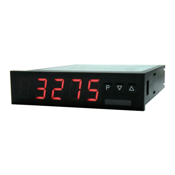
• red display from -19999...99999 digits (optional green, orange, blue or tricolour display)
Technical features:
• installation depth: 120 mm without plug-in screw terminal
• multi voltage power supply unit 100-240 VAC, alternatively 10-40 VDC galvanic isolated
• adjustment via factory setting or directly on the sensor signal
• red display from -19999...99999 digits (optional green, orange, blue or tricolour display)
• min/max-memory with adjustable permanent display
• installation depth: 120 mm without plug-in screw terminal
• 30 additional adjustable support points
• multi voltage power supply unit 100-240 VAC, alternatively 10-40 VDC galvanic isolated
• display flashing at threshold value exceedance / undercut
• adjustment via factory setting or directly on the sensor signal
• navigation keys for the triggering of Hold, Tara, display change, setpoint setting, alarm actuation
• min/max-memory with adjustable permanent display
• flexible alarm system with adjustable delay times
• 30 additional adjustable support points
• volume measurement (Totaliser)
• display flashing at threshold value exceedance / undercut
• mathematical functions like reciprocal value, square root, square and rounding
• constant setting / setpoint setting
• navigation keys for the triggering of Hold, Tara, display change, setpoint setting, alarm actuation
• sliding averaging
• flexible alarm system with adjustable delay times
• brightness control via parameter or front keys
• volume measurement (Totaliser)
• programming interlock via access code
• mathematical functions like reciprocal value, square root, square and rounding
• protection class IP65 at the front
• constant setting / setpoint setting
• plug-in screw terminal
• sliding averaging
• optional: 1 or 2 relay outputs
• brightness control via parameter or front keys
• optional: sensor supply
• optional: 1 independently scalable analog output
• programming interlock via access code
• optional: galv. isolated digital input for the triggering Tara, Hold, display change
• protection class IP65 at the front
• optional: interface RS232 or RS485
• plug-in screw terminal
• accessories: pc-based configuration-kit PM-TOOL with CD & USB adapter
• optional: 1 or 2 relay outputs
• on demand: devices for working temperatures of -25°C...60°C
• optional: sensor supply
• optional: 1 independently scalable analog output
• optional: galv. isolated digital input for the triggering Tara, Hold, display change
• optional: interface RS232 or RS485
M3_31GB.pdf update: 31.03.2015
• accessories: pc-based configuration-kit PM-TOOL with CD & USB adapter
• on demand: devices for working temperatures of -25°C...60°C
96x24
Advertisement
Table of Contents

Related Manuals for ACS contsys DAP-311 0 0S Series


Summary of Contents for ACS contsys DAP-311 0 0S Series
- Page 1 Operating Instructions User manual M3 User manual M3 Direct current / direct voltage signals 0-20 mA, 4-20 mA, 0-10 VDC Direct current / direct voltage signals 0-20 mA, 4-20 mA, 0-10 VDC DAP-311x0x0S Direct current/ Direct voltage signals0- 0/4-20 mA, 0-10 VDC Technical features: •...
- Page 2 Order code power supply 85-265VAC 10...40V DC galvanic seperated 85-265VAC with sensor supply 24VDC/50mA and digital input 10-40VDC with sensor supply 24VDC/50mA and digital input others function input 0/4...20 mA, 0...10V DC function output no output display with 2 relay outputs (changeover) display with analog output 0/4-20mA, 0-10V, switchable display + 1 relay with analog output 0/4-20mA, 0-10V, switchable others...
-
Page 3: Table Of Contents
Contents Brief description Assembly Electrical connection Function description and operation 4.1. Programming software PM-TOOL Setting up the device 5.1. Switching on 5.2. Standard parameterisation (flat operation level) Value assignment for the triggering of the signal input 5.3. Programming interlock „RUN“ Activation/Deactivation of the programming interlock or change into professional or flat operation level 5.4. -
Page 4: Brief Description
2. Assembly 2. Assembly 1. Brief description 1. Brief description 1. Brief description 1. Brief description The panel meter instrument M3-31 is a 5-digit device for direct current / direct voltage signals and a visual The panel meter instrument M3-31 is a 5-digit device for direct current / direct voltage signals and a visual The panel meter instrument DAP-311 is a 5-digit device for direct current / direct voltage signals and a threshold value monitoring via the display. -
Page 5: Electrical Connection
3. Electrical connection 3. Electrical connection Type DAP-311x0x0S Type M3-3VR5B.0001.S70BD supply 100-240 VAC 50/60 Hz, DC ±10% Type DAP-311x0x0S Type M3-3VR5B.0001.W70BD supply 10-40 VDC galv. isolated, 18-30 VAC 50/60 Hz Connection examples Below please find some connection examples that show practical applications. For devices with current inputs / voltage inputs, without sensor supply. - Page 6 3. Electrical connection DAP-311 devices M3 devices With current respectively voltage input in combination with a 24 VDC sensor supply. DAP-311x0x0S with digital input in combination DAP-311x0x0S with digital input and external with 24 VDC sensor supply voltage source ACS-CONTROL-SYSTEM GmbH l Lauterbachstr. 57 l D-84307 Eggenfelden l www.acs-controlsystem.de l info@acs-controlsystem.de...
-
Page 7: Function Description And Operation
4. Function description and operation 4. Function description and operation Operation The operation is divided into three different levels. Menu level (delivery status) This level was designed for the standard settings of the device. Only menu items which are sufficent to set the device into operation are displayed. -
Page 8: Programming Software Pm-Tool
4. Function description and operation Function chart: 4.1 Parameterisation software PM-TOOL: Part of the PM-TOOL are the software on CD and an USB-cable with device adapter. The connection happens via a 4-pole micromatch-plug on the back side of the device, to the PC-side the connection happens via an USB plug. -
Page 9: Setting Up The Device
5. Setting up the device 5. Setting up the device 5.1. Switching on Once the installation is complete, start the device by applying the voltage supply. Before, check once again that all electrical connections are correct. Starting sequence For 1 second during the switching-on process, the segment test (8 8 8 8 8) is displayed followed by an indication of the software type and, after that, also for 1 second the software version. - Page 10 5. Setting up the device Menu level Parameterisation level Setting the decimal point, dot: Default: 0 The decimal point on the display can be moved with [▲] [▼] and confirmed with [P]. The display then switches back to the menu level again. Setting up the display time, SEC: Default: 1.0 then...
- Page 11 5. Setting up the device Menu level Parameterisation level Hysteresis for limit values, HY-1: Default: 00000 The delayed reaction of the alarm is the difference to the threshold value, which is defined by the hysteresis. Function for threshold value undercut /exceedance, Fu-1: Default: high A limit value undercut is selected with Louu (for LOW = lower limit value), a limit value exceedance with High (for HIGH = higher limit value).
-
Page 12: Programming Interlock „Run
5. Setting up the device 5.3. Programming interlock „RUN“ Menu level Parameterisation level Activation / deactivation of the programming lock or completion of the standard parameterisation with change into menu group level (complete function range), run: Default: uloc Choose between the deactivated key lock Uloc (works setting) and the activated key lock Loc, or the change into the menu group level ProF with the navigation keys [▲] [▼]. -
Page 13: Extended Parametersation (Professional Operation Level)
5. Setting up the device 5.4. Extended parameterisation (Professional operation level) 5.4.1. Signal input parameters Menu group level Menu level Menu level Parameterisation level Selection of the input signal, TYPE: Default: sens.u There are several measuring input options: 0-20 mA, 4-20 mA or 0-10 VDC signals as works calibration (without application of the sensor signal) and SenSU (voltage) or SENSA (current) as sensor calibration (with the sensor applied). - Page 14 5. Setting up the device Menu level Parameterisation level Setting the decimal point, dot: Default: 0 The decimal point on the display can be moved with [▲] [▼] and confirmed with [P]. The display then switches back to the menu level again. Setting up the display time, SEC: Default: 1.0 then...
- Page 15 5. Setting up the device Menu level Parameterisation level Setting up the physical unit, UnIt: Default: no One can choose between the above shown physical units. It will be displayed on the 5th digit of the display. Number of additional setpoints, SPCt: Default: 00 30 additional setpoints can be defined to the initial value and final value, so linear sensor values are not linearised.
-
Page 16: General Device Parameters „Fct
5. Setting up the device Menu level Parameterisation level Display overflow, dI.OUE: Default: 99999 _ _ _ _ _ With this function the display overflow ( ) can be defined on a definite value. Input variable of process value, SIG.in: Default: a.meas With this parameter, the device can be controlled via the analog input signals a.meas = 0-20 mA, 4-20 mA or 0-10 VDC or via the digital signals of the interface M.bus = RS232/RS485 (Modbus... - Page 17 5. Setting up the device Menu level Parameterisation level Rounding of display values, round: Default: 00001 This function is for instable display values, where the display value is changed in increments of 1, 5, 10 or 50. This does not affect the resolution of the optional outputs. With [P] the selection is confirmed and the device changes into menu level.
- Page 18 5. Setting up the device Menu level Parameterisation level Minimum constant value, con.mi: Default: -i9999 The minimum constant value is adjusted from the smallest to the highest digit with the navigation keys [▲] [▼] and confirmed digit per digit with [P]. A minus sign can only be adjusted on the highest digit.
- Page 19 5. Setting up the device Menu level Parameterisation level Display flashing, FLASH: Default: no A display flashing can be added as additional alarm function either to single or to a combination of off-limit condition. With no, no flashing is allocated. Assignment (deposit) of key functions, tASt: Default: no For the operation mode, special functions can be deposited on the navigation keys [▲] [▼], in...
- Page 20 5. Setting up the device Menu level Parameterisation level Special function digital input, dIG.In: Default: no … For the operation mode, special functions can be deposited on the digital input. This function is actuated by pushing the key. With tArA the device is tared to zero and saved permanently as offset.
-
Page 21: Safety Parameters „Cod
5. Setting up the device 5.4.3. Safety parameters Menu group level Menu level Menu level Parameterisation level User code U.Code: Default: 0000 Via this code reduced sets of parameters can be set free. A change of the U.CodE can be done via the correct input of the A.CodE (master code). -
Page 22: Serial Parameters „Ser
5. Setting up the device Menu level Parameterisation level Back to menu group level, rEt: With [P] the selection is confirmed and the device changes into menu group level „–COD–“. 5.4.4. Serial parameters Menu group level Menu level Menu level Parameterisation level Device address, ADDR: Default: 001... -
Page 23: Analog Parameters „Out
5. Setting up the device 5.4.5. Analog output parameters Menu group level Menu level Menu level Parameterisation level Selection reference of analog output, OutPt: Default: actua The analog output signal can refer to different functions, in detail these are the current measurand, the min-value, the max-value, the totaliser function/sum function, the constant value or the difference between current measurand and constant value. - Page 24 5. Setting up the device Menu level Parameterisation level Overflow behaviour, O.FLoU: Default: edge To recognise and evaluate faulty signals, e.g. by a controller, the overflow behaviour of the analog output can be defined. As overflow can be seen either EdGE, that means the analog output runs on the set limits e.g.
-
Page 25: Relay Functions „Rel
5. Setting up the device 5.4.6. Relay functions Menu group level Menu level Menu level Parameterisation level Alarm relay 1, rEL-1: The same applies for relay 2 Default: al-1 …. …. Each setpoint (optional) can be linked up via 4 alarms (by default). This can either be inserted at activated alarms AL1/4 or deactivated alarms ALN1/4. -
Page 26: Alarm Parameters „Al1
5. Setting up the device Menu level Parameterisation level Alarms for relay 1, CoM-1: Default: a.i …. The allocation of the alarms to relay 1 happens via this parameter, one alarm or a group of alarms can be chosen. With [P] the selection is confirmed and the device changes into menu level. - Page 27 5. Setting up the device Menu level Parameterisation level Threshold values / limit values, LI-1: Default: 2000 The limit value defines the threshold, that activates/deactivates an alarm. Hysteresis for threshold values, HY-1: Default: 00000 The delayed reaction of the alarm is the difference to the threshold value, which is defined by the hysteresis.
-
Page 28: Totaliser (Volume Metering) „Tot
5. Setting up the device 5.4.8. Totaliser (Volume metering) Menu group level Menu level Menu level Parameterisation level State of totaliser, total: Default: off The totaliser realizes measurements on a time base of e.g. l/h, at this the scaled input signal is integrated by time and steadily (select Stead) or temporarily (select temp) saved. -
Page 29: Reset To Factory Settings
6. Reset to default values Menu level Parameterisation level Totaliser reset, tot.re: Default: ooooo The reset value is adjusted from the smallest to the highest digit with the navigation keys [▲] [▼] and digit per digit confirmed with [P]. After the last digit, the display switches back to the menu level. -
Page 30: Alarms / Relays
7. Alarms / Relays 7. Alarms / Relays This device has 8 virtual alarms that can monitor one limit value in regard of an undercut or exceedance. Each alarm can be allocated to an optional relay output S1-S2; furthermore alarms can be controlled by events like e.g. -
Page 31: Interfaces
8. Interfaces 8. Interfaces The interface RS485 is connected via a screened data line with twisted wires (Twisted-Pair). On each end of the bus segment a termination of the bus lines needs to be connected. This is neccessary to ensure a secure data transfer to the bus. -
Page 32: Sensor Aligment
9. Sensor alignment offset / final value 9. Sensor alignment offset / final value The device is equipped with a semi-automatic sensor calibration (SENSu/SENSa). A switching output operates the trimming resistor, which exists in some sensors. An adjustment of offset and final value takes place, after which the sensor can be used directly. -
Page 33: Technical Data
10. Technical data 10. Technical data Housing Dimensions 96x24x120 mm (BxHxD) 96x24x144 (154) mm (BxHxD) incl. plug-in terminal Panel cut-out 92.0 +0.8 x 22.2 +0.3 Wall thickness up to 10 mm Fixing screw elements Material PC polycarbonate, black, UL94V-0 Sealing material EPDM, 65 Shore, black Protection class standard IP65 (front), IP00 (back side) - Page 34 10. Technical data Output Sensor supply 24 VDC / 50 mA; 10 VDC / 50 mA Analog output 0/4-20 mA / burden ≤500 Ohm, 0-10 VDC / burden ≥10 kOhm, 16 bit Switching outputs Relay with change-over contact 250 VAC / 2 AAC; 30 VDC / 2 ADC Switching cycles 0.5 x 10 at contact load...
-
Page 35: Safety Advices
11. Safety advices 11. Safety advices 11. Safety advices 11. Safety advices 11. Safety advices 11. Safety advices Please read the following safety advices and the assembly in chapter 2 before installation and keep it for Please read the following safety advices and the assembly in chapter 2 before installation and keep it for Please read the following safety advices and the assembly in chapter 2 before installation and keep it for future reference. -
Page 36: Error Elimination
12. Error elimination 12. Error elimination Error description Measures The unit permanently indicates overflow. • The input has a very high measurement, check the measuring circuit. • With a selected input with a low voltage signal, it is only connected on one side or the input is open. •... - Page 37 ACS-CONTROL-SYSTEM GmbH l Lauterbachstr. 57 l D-84307 Eggenfelden l www.acs-controlsystem.de l info@acs-controlsystem.de...
- Page 38 Füllstand Pegel Druck Temperatur Durchfluss Regis- Sensorik Visua- Mess- trierung lisierung umformer Wir erwarten Ihren Anruf. ACS-CONTROL-SYSTEM GmbH Lauterbachstr. 57 D- 84307 Eggenfelden Tel: +49 (0) 8721-9668-0 Fax: +49 (0) 8721-9668-30 ACS-CONTROL-SYSTEM info@acs-controlsystem.de know how mit System www.acs-controlsystem.de Ihr Partner für Messtechnik und Automation...
Need help?
Do you have a question about the DAP-311 0 0S Series and is the answer not in the manual?
Questions and answers