Table of Contents
Advertisement
Quick Links
Advertisement
Table of Contents

Related Manuals for METREL MI 3115 PV


Summary of Contents for METREL MI 3115 PV
- Page 1 MI 3115 PV Analyser Inst ruct ion manual Ver.1.1.1, code no. 20 753 336...
- Page 2 / www.met rel.si DATA BACKUP AND LOSS: regularly backup and validat e t he int egrit y of backups of t he dat a. METREL HAS NO OBLIGATION OR LIABILITY FOR ANY LOSS, ALTERATION, DESTRUCTION, DAMAGE, CORRUPTION OR RECOVERY OF USER DATA, REGARDLESS OF WHERE THE DATA IS STORED.
-
Page 3: Table Of Contents
MI 3115 PV Analyser Table of Contents ABLE OF ONTENTS General description....................6 Warnings and not es ....................6 1.1.1 Saf et y warnings ....................6 1.1.2 Warnings relat ed t o saf et y of measurement f unct ions ........7 1.1.3... - Page 4 MI 3115 PV Analyser Table of Contents 5.1.2 Operat ions on measurement s ............... 31 5.1.3 Measurement st at uses ................. 32 5.1.4 Operat ions on St ruct ure object s ..............33 5.1.5 Searching in Memory Organizer ..............33 5.1.6...
- Page 5 MI 3115 PV Analyser Table of Contents Communications ....................62 USB and RS232 comm unicat ion wit h PC ............... 62 Comm unicat ion wit h A 1785 PV Remot e WL ............62 Technical specifications ..................64 10.1 Test and measurement s ..................64 10.1.1...
-
Page 6: General Description
• Metrel Auto Sequences® are designed as guidance to tests in order to significantly reduce testing time, improve work scope and increase traceability of the tests performed. Metrel assumes no responsibility for any Auto Sequence by any the selected Auto Sequence. -
Page 7: W Arnings Related To Safety Of Measurement Functions
MI 3115 PV Analyser General description to fire and can cause heavy damage. Users must be skilled to disconnect the PV system safely in this case. • Do not use the instrument in PV systems with voltages higher than 1500 V d.c. and/ or currents higher than 20 A d.c.! Otherwise, the instrument can be damaged. -
Page 8: General Notes
MI 3115 PV Analyser General description U (DC+/ DC-) 1500 V PE - not connect ed t o DC+ or DC- Type Riso=[Roc]: U (DC+/ DC-) PE - not connect ed t o DC+ or DC- At t he end of t est , capacit ive object s are discharged t o 30 V. -
Page 9: St Andards Applied
MI 3115 PV Analyser General description Mark on your equipment cert if ies t hat it meet s requirement s of all subject ed EU regulat ions. Mark on your equipment cert if ies t hat it meet s requirement s of all subject ed UK regulat ions. -
Page 10: Instrument Set And Accessories
MI 3115 PV Analyser Instrument set and accessories 2 Instrument set and accessories • MI 3115 PV Analyser inst rument • Mains cable C13/ schuko • Carrying bag (L) • Measurement lead, red, 3 m, banana/ banana • Measurement lead, blue, 3 m, banana/ banana •... -
Page 11: Instrument Description
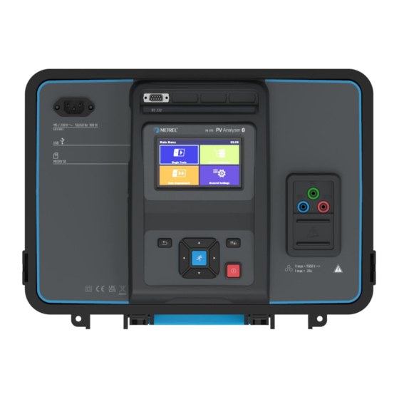
MI 3115 PV Analyser Instrument description 3 Instrument description Test connector options: Mains supply connect or Serial port USB comm unicat ion port MicroSD card slot Display... - Page 12 MI 3115 PV Analyser Instrument description Keypad ON/ OFF key Test connect or PE t erminal DC- t erminal DC+ t erminal Prot ect ion cover P/ S (probe) t erminal...
-
Page 13: Instrument Operation
MI 3115 PV Analyser Instrument operation 4 Instrument operation The inst rument can be manipulat ed via a keypad or t ouch screen. ON / OFF key Swit ch inst rument on / of f . To swit ch of f t he inst rument press key f or 2 s. -
Page 14: General Meaning Of T Ouch Gest Ures
MI 3115 PV Analyser Instrument operation Tap (briefly touch surface with fingertip) is used to: • Select appropriat e opt ion. • Conf irm select ed opt ion. • St art and st op measurement s. Swipe (press, move, lift) up/ down is used to: •... -
Page 15: Saf Et Y Checks, Sym Bols, Messages
MI 3115 PV Analyser Instrument operation Activates alphabetic characters. English keyboard layout. Greek keyboard layout. Russian keyboard layout. Returns to the previous menu without changes. Note • If Backspace is held f or 2 s, all charact ers will be select ed. - Page 16 MI 3115 PV Analyser Instrument operation Time synchronizat ion warning. Af t er conf irmat ion A 1785 PV Remot e WL accept s t ime f rom inst rument . Warning t hat t ime synchronizat ion is not possible while remot e unit is logging.
- Page 17 MI 3115 PV Analyser Instrument operation Measurement is running, consider displayed warnings. W arning! A very high and dangerous volt age is / will be present on t he inst rument out put ! The inst rument aut omat ically discharges t est ed object af t er f inished insulat ion measurement .
-
Page 18: Bluetooth And W I-Fi Connections
MI 3115 PV Analyser Instrument operation Test passed. Result is inside predef ined limit s. Test f ailed. Result is out of predef ined limit s. Measurement is abort ed. Consider displayed warnings and messages. In R ISO PV and IEC 62446 Aut ot est f unct ion Roc... -
Page 19: Battery Indication
MI 3115 PV Analyser Instrument operation The t erminal volt age m onit or displays volt age and act ive t est t erminals indicat ion. PE t erminal should also be connect ed f or correct input volt age condit ion. -
Page 20: General Set T Ings Menu
MI 3115 PV Analyser Instrument operation Single Test Menu f or select ing single t est s Auto Sequences® Menu f or select ing Aut o sequences Menu f or working wit h st ruct ured t est object s... -
Page 21: Settings
MI 3115 PV Analyser Instrument operation Set t ing dif f erent syst em and measuring Settings paramet ers Bluetooth init. Bluet oot h / Wi-Fi modul init ializat ion Fact ory set t ings Initial Settings About Inst rument dat a 4.6.1 Settings... -
Page 22: W I-Fi Settings
MI 3115 PV Analyser Instrument operation 4.6.2 W i-Fi settings Ref er t o chapt er Communication with A 1785 PV Remote W L and A 1785 PV Remote W L Instruction manual f or det ailed inf ormat ion. -
Page 23: About
MI 3115 PV Analyser Instrument operation 4.6.5 About In t his menu inst rument dat a (name, serial number, FW (f irmware) and HW (hardware) version, prof ile code, HD (hardware document at ion) version, and dat e of calibrat ion) can be viewed. -
Page 24: Managing Accounts
MI 3115 PV Analyser Instrument operation User sign out: select Sign out Change user password (individual users can change t heir password): Select Change password , set new password. Account manager sign out : is aut omat ic by exit ing t he Account manager menu. -
Page 25: Inst Rument Prof Iles
MI 3115 PV Analyser Instrument operation The inst rument uses specif ic syst em and measuring set t ings in regard t o t he scope of work or count ry it is used. These specif ic set t ings are st ored in inst rument prof iles. By def ault , each inst rument has at least one prof ile act ivat ed. - Page 26 MI 3115 PV Analyser Instrument operation Workspaces are st ored on microSD card on direct ory PROJ ECTS, while Export s are st ored on direct ory EXPORTS. Export f iles can be read by Met rel applicat ions t hat run on ot her devices.
-
Page 27: Aut O Sequence® Groups
MI 3115 PV Analyser Instrument operation Import Import select ed Export t o a Workspace Delete Delet e select ed Export The Aut o Sequences in t he inst rument can be organized by using list s. In a list a group of similar Aut o Sequences is st ored. -
Page 28: Pv M Odules
MI 3115 PV Analyser Instrument operation 4.10 In t his menu a list of PV modules and t heir dat a can be managed. The PV modules dat a f rom t his list is used in measurement s, f or calculat ion of nominal and STC result s. -
Page 29: Import Of List Of Pv Modules
MI 3115 PV Analyser Instrument operation Parameters of PV module PV m odule name Module For more inf ormat ion see PV module configurat ion Manufacturer PV m odule manuf act urer Pmax Nominal power of PV module Volt age at maximum power point... -
Page 30: Memory Organizer
MI 3115 PV Analyser Memory Organizer 5 Memory Organizer Memory Organizer is an environment f or st oring and working wit h t est dat a. The dat a is organized in a mult ilevel t ree st ruct ure wit h St ruct ure object s and Measurement s. For a list... -
Page 31: Operations On Measurements
MI 3115 PV Analyser Memory Organizer 5.1.2 Operations on measurements Start Test St art a new measurement Clone Copy select ed measurement as an empt y measurement under t he same St ruct ure object Copy a select ed measurement as an empt y measurement t o... -
Page 32: Measurement Statuses
MI 3115 PV Analyser Memory Organizer 5.1.3 Measurement statuses Measurement st at uses indicat e t he st at us of a measurement or a group of measurement s in t he Memory Organizer. Statuses of Single tests Passed f inished single t est wit h t est result s... -
Page 33: Operations On Structure Objects
MI 3115 PV Analyser Memory Organizer 5.1.4 Operations on Structure objects Start Test St art a new measurement (proceeds t o menus f or select ion of measurement ) Parameters View / edit paramet ers Add a new empt y measurement . Menu f or adding new measurement... -
Page 34: Changing Pv Modules And Other Parameters In Already Performed Measurements
MI 3115 PV Analyser Memory Organizer Header line (W orkspace), Search Ent er Search menu Search Search according t o st ruct ure element name and st at us Clear filters Clear set f ilt ers in Search menu Operations on found structure objects... - Page 35 MI 3115 PV Analyser Memory Organizer • Nominal and STC values will change accordingly. Measured dat a and environment al dat a will st ay t he same. Af t er updat e is f inished, conf irmat ion wit h number of updat ed st ruct ures and measurement s is displayed.
-
Page 36: Single Tests
MI 3115 PV Analyser Single tests 6 Single tests In single t est main menu t wo modes f or select ing single t est s are available. Groups View groups of similar t est s View last made measurement s... -
Page 37: Single Test Start Screen
MI 3115 PV Analyser Single tests 6.2.1 Single test start screen Start test St art single t est Parameters , or tap on Parameters field Set paramet ers/ limit s of single t est Prev Previous screen Next Next screen... -
Page 38: Single Test Result Screen
MI 3115 PV Analyser Single tests 6.2.3 Single test result screen Start test St art a new single t est Save t he result Save A new measurement was started from a The measurement will be saved under t he... -
Page 39: Editing Graphs
MI 3115 PV Analyser Single tests 6.2.4 Editing graphs Options for editing graphs (start screen or after measurement is finished) Plot edit Open cont rol panel f or edit ing graphs Increase scale f act or f or y-axis y-range Up... -
Page 40: Single Test (Inspection) Start Screen
MI 3115 PV Analyser Single tests Overall st at us Opt ions St at us f ields Child it ems It em 6.3.1 Single test (inspection) start screen Start test St art t he inspect ion View help screens Help 6.3.2 Single test (Inspection) screen during test... -
Page 41: Single Test (Inspection) Result Screen
MI 3115 PV Analyser Single tests Hint Tap on or use key t o set st at us. Rules for automatic applying of statuses • The parent it ems will aut omat ically The f ail st at us has highest priorit y. A f ail... -
Page 42: Help Screens
MI 3115 PV Analyser Single tests can select anot her St ruct ure object or creat e a new St ruct ure object . By pressing t he Save key in Memory organizer menu t he inspect ion is saved under select ed locat ion. -
Page 43: On-Line Synchronization Of Environmental Data Between Pv Remote W L And Instrument
MI 3115 PV Analyser Single tests If the wireless connection is established between the PV remote W L and the instrument during the PV test t he environment al dat a f rom t he remot e unit will be aut omat ically sent t o t he inst rument and considered in t he t est . -
Page 44: Synchronization Of Environmental Data Between Pv Remote W L And Instrument After The Test
MI 3115 PV Analyser Single tests 6.4.2 Synchronization of environmental data between PV Remote W L and instrument after the test Following dat a are logged wit h PV remot e WL and can be synchronized wit h t he inst rument... -
Page 45: Manual Entry Of Environmental Data
MI 3115 PV Analyser Single tests • If PV Remot e WL t ime is ahead of t he displayed. • Once a PV measurement was updat ed wit h valid dat a f rom t he PV Remot e WL, f urt her updat es are not possible. -
Page 46: Single T Est Measurement S
MI 3115 PV Analyser Single tests Note • 6.5.1 Visual inspection Test results / sub-results Pass, Fail, Checked Test circuit 6.5.2 R low, 200 mA resistance measurement Test results / sub-results Resist ance Result at posit ive t est polarit y... -
Page 47: Compensation Of Test Leads
MI 3115 PV Analyser Single tests Test circuits 6.5.3 Compensation of test leads • Resist ance of t est lead(s) and cables can be compensat ed. Compensat ion is possible in R low f unct ion. Connection for compensating the resistance of test leads Procedure for compensation of test leads Select single t est and it s paramet ers. -
Page 48: Uoc/ Isc
MI 3115 PV Analyser Single tests Test volt age Measured open-circuit volt age Uoc_m Test parameters Nominal test voltage Uiso [250 V, 500 V, 1000 V, 1500 V] Type of test Type Riso [Roc+, Roc-, Roc] Duration Durat ion [Of f , 5... - Page 49 MI 3115 PV Analyser Single tests Tcell (5 min) PV cell t emperat ure 5 min bef ore t est PV cell t emperat ure 10 min bef ore t est Tcell (10 min) Tcell (15min) PV cell t emperat ure 15 min bef ore t est...
-
Page 50: I/ U Curve
MI 3115 PV Analyser Single tests 6.5.6 I/ U curve Test results / sub-results Uoc_m Measured open-circuit volt age Isc_m Measured short -circuit current Umpp_m Measured volt age (MPP) Impp_m Measured current (MPP) Pmpp_m Measured maximum power point Open-circuit volt age (STC) - Page 51 MI 3115 PV Analyser Single tests ∆ Relat ive change of Isc ∆ Relat ive change of Umpp Umpp ∆ Relat ive change of Impp Impp ∆ Relat ive change of Pmpp Pmpp Measured f ill f act or FF_m...
-
Page 52: Aut Omat Ic Measurement Iec 62446 Aut Ot Est
MI 3115 PV Analyser Single tests Test limit ∆ ∆ ∆ High limit ( Pmpp) [Of f , Cust om, 5 % 50 %] Pmpp limit ( Pmpp) Test circuit 6.5.7 Automatic measurement IEC 62446 Autotest Test results / sub-results... -
Page 53: Environment
MI 3115 PV Analyser Single tests Duration Durat ion [5 s 60 s] Number of PV modules in series [Cust om, 1 Number of modules in PV string Number of PV strings Number of PV modules / st rings in parallel [Cust om, 1... - Page 54 MI 3115 PV Analyser Single tests Irradiance at t ime of measurement PV cell t emperat ure at t ime of measurement Tcell Tamb Ambient t emperat ure at t ime of measurement Tcell (5 min) PV cell t emperat ure 5 min bef ore t est...
-
Page 55: Auto Sequences
MI 3115 PV Analyser Auto Sequences® 7 Auto Sequences® Aut o Sequences® are pre-programmed sequences of measurement s. The Aut o Sequences can be pre-programmed on PC wit h t he Met rel ES Manager sof t ware and uploaded t o t he inst rument . -
Page 56: Organization Of Auto Sequences® In Auto Sequences® Menu
MI 3115 PV Analyser Auto Sequences® 7.1.1 Organization of Auto Sequences® in Auto Sequences® menu The Aut o Sequence® menu can be organized in a st ruct ural manner wit h f olders, sub-f olders and Aut o Sequences. Aut o Sequence in t he st ruct ure can be t he original Aut o Sequence or a short cut t o t he original Aut o Sequence. -
Page 57: Auto Sequence® View Menu
MI 3115 PV Analyser Auto Sequences® 7.2.1 Auto Sequence® view menu Header is selected Aut o Sequence name Descript ion Opt ions Single t est s Header Start Test St art of Aut o Sequence Single test is selected Aut o Sequence name... -
Page 58: Indication Of Loops
MI 3115 PV Analyser Auto Sequences® Enable mult iple point s t est ing: set multiple points , see Managing multiple point s 7.2.2 Indication of Loops programmed. This means t hat t he marked single t est will be carried out as many t imes as t he individual measurement . -
Page 59: Auto Sequence Result Screen
MI 3115 PV Analyser Auto Sequences® For t he act ual list and descript ion of f low commands see Met rel ES Manager Sof t ware help f ile The offered options in the control panel depend on the selected single test, its result and the programmed test flow. - Page 60 MI 3115 PV Analyser Auto Sequences® Descript ion St at us of single t est Single t est s St art a new Aut o Sequence Start Test View View result s of individual measurement s. Comment Add comm ent t o Aut o Sequence...
-
Page 61: Maintenance
MI 3115 PV Analyser Maintenance 8 Maintenance It is essent ial t hat all measuring inst rument s are regularly calibrat ed in order f or t he t echnical specif icat ion list ed in t his manual t o be guarant eed. We recomm end an annual calibrat ion. -
Page 62: Communications
MI 3115 PV Analyser Communications 9 Communications The inst rument can comm unicat e wit h t he Met rel ES Manager PC sof t ware. The f ollowing act ions are support ed: • Saved result s and Tree st ruct ure f rom Memory organizer can be downloaded and st ored t o a PC or android device. - Page 63 MI 3115 PV Analyser Communications Place inst rument and PV Remot e WL close t o each ot her. Swit ch on bot h, t he inst rument and PV Remot e WL t o synchronize t ime. Dat e & t ime synchronizat ion occurs aut omat ically every t ime when inst rument and PV Remot e WL are swit ched on.
-
Page 64: Technical Specifications
MI 3115 PV Analyser Technical specifications 10 Technical specifications 10.1 10.1.1 R ISO PV Insulation resistance General Nominal d.c. t est volt ages U ..... 250 V, 500 V, 1000 V, 1500 V Open-circuit volt age ......-0 % / +20 % of nominal volt age ... -
Page 65: R Low - 200 Ma Resistance Measurement
Maximum current ........20 A Maximum power of PV st ring ....24 kW Connect ion ..........st andard 4 mm METREL saf et y banana jacks I-U curve t racking point s ......min. 512 point s (t ime equidist ant ) Sampling rat e ......... -
Page 66: Uoc/ Isc Measurements
Maximum current ........20 A Maximum power of PV st ring ....24 kW Connect ion ..........st andard 4 mm METREL saf et y banana jacks Accuracy of STC values is based on accuracy of measured elect rical quant it ies, accuracy of environment al paramet ers, and ent ered param et ers of PV module. -
Page 67: Environmental Parameters
MI 3115 PV Analyser Technical specifications DC current Range (A) Resolution (A) Accuracy 0.99 0.01 ±6 digit s Isc_m 9.99 0.01 ±(1 % of reading + 3 digit s) 10.00 19.99 0.01 ±1 % of reading The error in operat ing condit ions could be at most t he error f or ref erence condit ions ±2 % of measured value. - Page 68 MI 3115 PV Analyser Technical specifications RS232 ........... 1 port , DB9 f emale USB ............USB 2.0, st andard Type-B Bluet oot h ..........v4.2 BR/ EDR and BLE specif icat ion Wi-Fi ............ 802.11 b/ g/ n (802.11n up t o 150 Mbps) (Only f or comm unicat ion wit h A 1785 - PV Remot e WL) Emission ..........
-
Page 69: Appendix A - Remote Operation
MI 3115 PV Analyser Appendix A - Remote operation 11 Appendix A - Remote operation Dif f erent possibilit ies of remot e operat ion of t he inst rument are support ed. 11.1 The Met rel ES Manager SW applicat ion f or Windows. Among a plent y of f eat ures it enables also a complet e cont rol over t he inst rument . -
Page 70: Appendix B - Structure Objects
MI 3115 PV Analyser Appendix B - Struct ure objects 12 Appendix B - Structure objects Symbol Default name Description Node Node Object Object Invert er PV invert er Combiner box PV Combiner box St ring PV st ring Module... -
Page 71: Appendix C - Profile Notes
MI 3115 PV Analyser Appendix C - Profile Not es 13 Appendix C - Profile Notes So f ar t here are no specif ic prof ile not es f or t his inst rument . -
Page 72: Appendix D - Pv Measurements - Calculated Values
MI 3115 PV Analyser Appendix D - PV measurements - calculat ed values 14 Appendix D - PV measurements - calculated values �� �� Calculation to STC �� �� Measured volt age and current are calculat ed t o STC as f ollows: ������... - Page 73 MI 3115 PV Analyser Appendix D - PV measurements - calculat ed values �� = �� ∙ �� ������ ������,������ ������,������ Equation Instrument Description �� symbol abbreviation ������,������ Umpp (STC) Maximum power point volt age calculat ed t o STC ��...
- Page 74 MI 3115 PV Analyser Appendix D - PV measurements - calculat ed values �� ������,������ Maximum power point volt age calculat ed t o STC Umpp (STC) �� values ������,������ �� Impp (NOM) Nominal maximum power point current ������,������ Maximum power point current calculat ed t o STC Impp (STC) ��...
- Page 75 �� �� ∙ �� MI 3115 PV Analyser Appendix D - PV measurements - calculat ed values �� ∙ ����,�� ����+ ����− �� �� − �� ���� ������ ����+ ����− Equation Instrument Description �� symbol abbreviation ����+ �� Roc+ Measured resist ance bet ween DC+ and PE ����−...
- Page 76 MI 3115 PV Analyser Contacts METREL d.o.o. Ljubljanska cest a 77 SI-1354 Horjul Slovenia Phone: +386 (0)1 75 58 200 Fax: +386 (0)1 75 49 226 Email: inf o@met rel.si...
Need help?
Do you have a question about the MI 3115 PV and is the answer not in the manual?
Questions and answers