Table of Contents
Advertisement
Quick Links
Advertisement
Table of Contents

Related Manuals for METREL EurotestXE MI 3102H


Summary of Contents for METREL EurotestXE MI 3102H
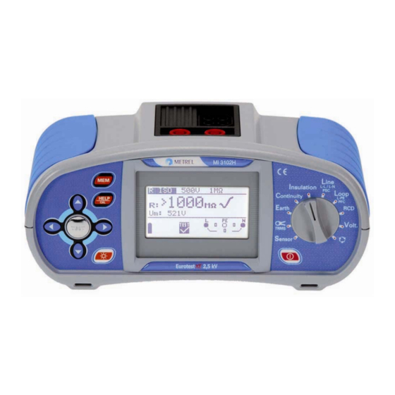
- Page 1 EurotestXE 2,5 kV MI 3102H Instruction manual Version 1.2, Code No. 20 751 565...
- Page 2 Mark on your equipment certifies that this equipment meets the requirements of the EU (European Union) concerning safety and interference causing equipment regulations. No part of this publication may be reproduced or utilized in any form or by any means without permission in writing from METREL.
-
Page 3: Table Of Contents
MI 3102H Table of contents Preface ......................5 Safety and operational considerations ............. 6 Warnings and notes..................6 Batteries ..................... 9 Charging ..................... 9 Precautions on charging of new battery cells or cells unused for a longer period ....................... 10 Standards applied.................. - Page 4 MI 3102H Table of contents 5.3.7 Trip-out time ..................39 5.3.8 Trip-out current..................41 5.3.9 Autotest ....................42 Fault loop impedance and prospective fault current ......... 46 5.4.1 Fault loop impedance ................46 5.4.2 RCD trip-lock function ................48 Line impedance and prospective short-circuit current ......51 Phase sequence testing ................
-
Page 5: Preface
In order for operator to be familiar enough with measurements in general and typical applications it is advisable to read Metrel handbook Guide for testing and verification of low voltage installations. The instrument is equipped with all accessories necessary for comfortable testing. It is... -
Page 6: Safety And Operational Considerations
MI 3102H Safety and operational considerations 2 Safety and operational considerations 2.1 Warnings and notes In order to reach high level of operator’s safety while carrying out various tests and measurements using the EurotestXE 2,5 kV instrument, as well as to keep the test equipment undamaged, it is necessary to consider the following general warnings: symbol on the instrument means »Read the Instruction manual with special care to safety operation«. - Page 7 MI 3102H Safety and operational considerations Warnings related to measurement functions Insulation resistance Insulation resistance measurement should only be performed on de-energized objects! When measuring insulation resistance between installation conductors all loads must be disconnected and all switches closed! Do not touch the test object during the measurement or before it is fully discharged! Risk of electric shock! When an insulation resistance measurement has been performed on a capacitive object automatic discharge may not be done immediately! Warning message...
- Page 8 MI 3102H Safety and operational considerations Before performing continuity measurement compensate test lead resistance if necessary. The compensation is performed in LowΩ function. RCD functions Parameters set in one function are also kept for other RCD functions! The measurement of contact voltage does not normally trip an RCD. However, the trip limit may be exceeded as a result of leakage current flowing to the PE protective conductor or a capacitive connection between L and PE conductors.
-
Page 9: Batteries
1000:1, appropriate measurement range, consider error of test clamp when evaluating measured results)! Current clamps Metrel A 1074 and A 1019 are suitable for use with MI 3102 EurotestXE 2,5 kV instrument in range 0.2 A … 20 A. Below 0.2 A they can be used as indicator only. -
Page 10: Precautions On Charging Of New Battery Cells Or Cells Unused For A Longer Period
MI 3102H Safety and operational considerations Figure 2.1: Power supply socket polarity Note: Use only power supply adapter delivered from manufacturer or distributor of the test equipment to avoid possible fire or electric shock! 2.4 Precautions on charging of new battery cells or cells unused for a longer period Unpredictable chemical processes can occur during charging of new battery cells or cells that were unused for a longer period of time (more than 3 months). -
Page 11: Standards Applied
MI 3102H Safety and operational considerations 2.5 Standards applied The EurotestXE 2,5 kV instrument is manufactured and tested in accordance with the following regulations: Electromagnetic compatibility (EMC) EN 61326 Electrical equipment for measurement, control and laboratory use – EMC requirements Class B (Hand-held equipment used in controlled EM environments) Safety (LVD) -
Page 12: Instrument Description
MI 3102H Instrument description 3 Instrument description 3.1 Front panel Figure 3.1: Front panel Legend: 1..ON/OFF key, to switch on or off the instrument. The instrument is automatically switched off 10 minutes after the last key was pressed or function switch rotated. 2.. -
Page 13: Connector Panel
MI 3102H Instrument description 3.2 Connector panel > 550V Figure 3.2: Connector panel Legend: 1..Test connector. Warning! Maximal allowed voltage between test terminals and ground is 600 V! Maximal allowed voltage between test terminals is 550 V! In resistance to earth function test connector terminals are used as follows: L/L1 black test lead is used for the auxiliary earth electrode (H). -
Page 14: Back Panel
MI 3102H Instrument description 3.3 Back panel Figure 3.3: Back panel Legend: 1..Battery/fuse compartment cover. 2..Information label. 3..Fixing screws for battery/fuse compartment cover. Fuse Fuse Fuse S/N XXXXXXXX SIZE AA SIZE AA SIZE AA Figure 3.4: Battery and fuse compartment... -
Page 15: Bottom View
MI 3102H Instrument description Legend: 1..Fuse F1. 2..Fuse F2. 3..Fuse F3. 4..Serial number label. 5..Battery cells (size AA). 6..Battery holder. 3.4 Bottom view Figure 3.5: Bottom view Legend: 1..Information label. 2..Neck belt openings. 3.. -
Page 16: Carrying The Instrument
MI 3102H Instrument description 3.5 Carrying the instrument With the neck carrying belt supplied in standard set, various possibilities of carrying the instrument are available. Operator can choose appropriate one on basis of his / her operation, see the following examples: The instrument is hung around operator's neck only - quick placing and... -
Page 17: Instrument Set And Accessories
MI 3102H Instrument description 3.6 Instrument set and accessories Instrument EurotestXE 2,5 kV MI 3102H Soft carying bag Soft carying neck belt Test lead, 3 × 1.5 m Measuring accessories 2.5 kV insulation test lead, 2 × 1.5 m Tip commander with two function keys, 1.5 m Schuko plug test cable Test probe, 3 pcs (black, blue, green) Crocodile clip, 3 pcs (black, blue, green) -
Page 18: Instrument Operation
MI 3102H Instrument operation 4 Instrument operation 4.1 Meaning of symbols and messages on the instrument display The instrument display is divided into four sections: Figure 4.1: Display outlook Legend: 1..Function and parameter line. In the top display line the measuring function/sub-function and parameters are displayed. -
Page 19: Message Field - Battery Status
MI 3102H Instrument operation 4.1.2 Message field – battery status Battery power indication. Low battery indication. Battery pack is too weak to guarantee correct result. Replace the batteries. Recharging is running (if power supply adapter is connected). 4.1.3 Message field – measurement warnings / messages Warning! High voltage is applied to the test terminals. -
Page 20: Result Field
MI 3102H Instrument operation Fuse F1 (continuity circuit) blown or not inserted. Noise voltage is present between H and E or S test terminals. Resistance of auxiliary earth electrode is higher than 100×R . Check the auxiliary earth electrode. Probe resistance is higher than 100×R . -
Page 21: Sound Warnings
MI 3102H Instrument operation 4.1.6 Sound warnings Pressed key deactivated. The shortest sound Sub-function is not available. Pressed key activated. Measurement has been started after pressing the TEST Short sound key. Consider any displayed warnings during measurement. Measurement is prohibited. Consider any displayed Long sound warnings and check online voltage/terminal monitor! Warning! Phase voltage on the PE terminal! Stop all the... -
Page 22: Setting Measurement Parameters And Limits
MI 3102H Instrument operation 4.3 Setting measurement parameters and limits By using keys select the parameter / limit value you want to edit. By using keys the selected parameter can be set. Once the measurement parameters are set the settings are kept until new changes are made or the original settings are recalled. -
Page 23: Prospective Short/Fault Current Scaling Factor Adjustment
MI 3102H Instrument operation 4.5.1 Prospective short/fault current scaling factor adjustment Select SET I FACTOR in Setup menu by using keys and press the TEST key to enter the Prospective short/fault current scaling factor adjustment menu. Figure 4.5: Scaling factor adjustment menu keys to adjust the scaling factor. -
Page 24: Plug / Tip Commander Support
MI 3102H Instrument operation 4.5.4 Plug / Tip commander support Select COMMANDER in Setup menu by using keys and press the TEST key to switch on / off the support for remote commanders. If disable is selected then keys on Plug / Tip commander are disabled (except backlight key). -
Page 25: Display Contrast Adjustment
MI 3102H Instrument operation LOOP Fuse type: none selected (∗F) Z LOOP Fuse current rating: none selected (∗A) Zs (rcd) Fuse tripping current: none selected (∗ms) Selected function: RCD Uc Contact voltage – RCD Uc Nominal differential current: I =30 mA ΔN Trip-out time –... -
Page 26: Measurements
Resistance of semi-conductive (antistatic) floors. For additional general information concerning insulation resistance measurement refer to the Metrel handbook Guide for testing and verification of low voltage installations. How to perform insulation resistance measurement: Select Insulation function with the function selector switch. With Step 1 keys you can switch between R ISO or DIAG. - Page 27 MI 3102H Measurements Connect test cable to the EurotestXE 2,5 kV instrument. Set the following measuring parameter and limit values: Step 2 Nominal test voltage, Low limit resistance value. Connect test cable to the item under test. Follow the connection diagram Step 3 shown in figure 5.2 to perform insulation resistance measurement.
-
Page 28: The Dar And Pi Diagnostic
MI 3102H Measurements stabilised. Actual measured results are shown on the display during measurement. After the TEST key is released the last measured results are displayed, together with the PASS/FAIL indication (if applicable). Figure 5.4: Example of insulation resistance measurement results Displayed results: R .....Insulation resistance, Um..Instrument test voltage. - Page 29 PI is the ratio of Insulation Resistance values measured after 1 minute and after 10 minutes. The DC test voltage is present during the whole period of the measurement PI = For additional information regarding PI and DAR diagnostic, please refer to Metrel’s handbook Modern Insulation Testing. How to perform diagnostic test: Select Insulation function with the function selector switch.
- Page 30 MI 3102H Measurements Figure 5.6: Example of diagnostic tests results Displayed results: Insulation resistance, Instrument test voltage, Resistance after 60 seconds, Dielectric Absorption Ration, Polarization Index. Save displayed results for documentation purposes. Refer to chapter 6.1. Saving results Notes: Diagnostic tests are available only for test voltages 500 V , 1000 V 2500V If any insulation resistance values (R...
-
Page 31: Continuity
MI 3102H Measurements 5.2 Continuity Two Continuity sub-functions are available: LowΩ resistance, Continuity. 5.2.1 LowΩ resistance This test is used to ensure electric safety and correct connection of all protective conductors, earth conductors or bonding conductors. The measurement of LowΩ resistance is performed with automatic pole reversal of the test voltage and the test current of more than 200 mA. - Page 32 MI 3102H Measurements 3. Press the CAL key. After performing test leads compensation compensated test leads indicator is displayed. 4. In order to annul potential compensation follow the procedure described in this step with open test leads. After annulling compensation, the compensation indicator disappears.
- Page 33 MI 3102H Measurements Check the displayed warnings and online voltage/terminal monitor before Step 5 starting measurement. If OK, press the TEST key. After performing the measurement results appear on the display together with the PASS/FAIL indication (if applicable). Ω Figure 5.12 Example of Low resistance measurement results Displayed results: R .....Main LowΩ...
-
Page 34: Continuity
(few mA). In general function serves as an ordinary Ω-meter with low-test current. Function can also be used to test inductive components. For additional information concerning continuity measurement refer to the Metrel handbook Guide for testing and verification of low voltage installations. How to perform Continuity measurement Select Continuity function with the function selector switch first. - Page 35 MI 3102H Measurements Figure 5.15: Connection of tip commander Check the displayed warnings and online voltage/terminal monitor before Step 4 starting measurement. If OK, press the TEST key to start the measurement. Actual measuring result with PASS/FAIL indication (if applicable) is shown on the display during measurement.
-
Page 36: Testing Rcds
MI 3102H Measurements 5.3 Testing RCDs When testing RCDs, the following sub-functions can be performed: Contact voltage measurement, Trip-out time measurement, Trip-out current measurement, RCD autotest. In general the following parameters and limits can be set when testing RCDs: Limit contact voltage, Nominal differential RCD trip-out current, Multiplier of nominal differential RCD trip-out current, RCD type,... -
Page 37: Testing Selective (Time-Delayed) Rcds
Δ For additional general information concerning contact voltage measurement refer to the Metrel handbook Guide for testing and verification of low voltage installations . How to perform contact voltage measurement Select RCD function with the function selector switch first. Use the... - Page 38 MI 3102H Measurements Set the following measuring parameters and limit values: Step 2 Nominal residual current, RCD type, Limit contact voltage. Follow the connection diagram shown in figure 5.19 to perform contact Step 3 voltage measurement. Use the Help function if necessary. Figure 5.19: Connection of plug test cable or 3-wire test lead Check the displayed warnings and online voltage/terminal monitor before Step 4...
-
Page 39: Trip-Out Time
200 ms 150 ms Test current of ½ × I cannot cause trip-out of the RCDs. ΔN For additional general information concerning trip-out time measurement refer to the Metrel handbook Guide for testing and verification of low voltage installations . - Page 40 MI 3102H Measurements How to perform trip-out time measurement Select RCD function with the function selector switch first. Use the keys to Step 1 select Trip-out time function. The following menu is displayed: Figure 5.21: Trip-out time measurement menu Connect test cable to the EurotestXE 2,5 kV instrument. Set the following measuring parameters: Step 2 Nominal differential trip-out current,...
-
Page 41: Trip-Out Current
DC residual currents), until the RCD is tripped. For additional general information concerning trip-out current measurement refer to the Metrel handbook Guide for testing and verification of low voltage installations . How to perform trip-out current measurement Select RCD function with the function selector switch first. Use the... -
Page 42: Autotest
MI 3102H Measurements Figure 5.24: Example of trip-out current measurement result Displayed results: .....Trip-out current, Δ ..Contact voltage, tI .....Trip-out time. Save displayed results for documentation purposes. Refer to chapter 6.1. Saving results. Classification of RCD I results when saved Three RCD I sub-functions are available for saving after pressing the MEM key. - Page 43 MI 3102H Measurements 5.3.9.1 How to perform RCD autotest – standard version Select RCD function with the function selector switch first. Use the keys Step 1 to select AUTO function. The following menu is displayed: Figure 5.25: RCD autotest menu Connect test cable to the EurotestXE 2,5 kV instrument.
- Page 44 MI 3102H Measurements Figure 5.27: Step 2 RCD autotest results After performing step 2 the RCD autotest sequence automatically proceeds with step 3. 3. Trip-out time measurement with the following measurement parameters: Test current of I ΔN Test current started with the positive half-wave at 0 Measurement normally trips an RCD within allowed time period.
- Page 45 MI 3102H Measurements After re-switching the RCD, the autotest sequence automatically proceeds with step 6. 6. Trip-out time measurement with the following measurement parameters: Test current of 5 × I ΔN Test current started with the negative half-wave at 180 Measurement normally trips an RCD within allowed time period.
-
Page 46: Fault Loop Impedance And Prospective Fault Current
). For additional general information concerning fault loop impedance measurement refer to the Metrel handbook Guide for testing and verification of low voltage installations . How to perform fault loop impedance measurement Select LOOP function with the function selector switch first. Use the... - Page 47 MI 3102H Measurements Set the following measuring parameters: Step 2 Fuse type, Fuse current rating, Fuse trip-out time, scaling factor (see chapter 4.5.1 Prospective short/fault current scaling factor adjustment ). The complete list of available fuse types can be found in Appendix A. Follow the connection diagram shown in the figure 5.33 to perform fault loop Step 3 impedance measurement.
-
Page 48: Rcd Trip-Lock Function
Setup menu (see chapter 4.5.1 Prospective short/fault current scaling factor adjustment ). For additional general information concerning fault loop impedance measurement refer to the Metrel handbook Guide for testing and verification of low voltage installations . - Page 49 MI 3102H Measurements How to perform RCD trip-lock measurement Select LOOP function with the function selector switch first. Use the keys Step 1 to select RCD trip-lock Zs(rcd) sub-function. The following menu is displayed: Figure 5.35: Trip-lock function menu Connect test cable to the EurotestXE 2,5 kV instrument. Set the following measuring parameters: Step 2 Fuse type,...
- Page 50 MI 3102H Measurements Classification of Zs(rcd) results when saved Three Zs(rcd) sub-functions are available for saving after pressing the MEM key. Zs rcd L1/PE, Zs rcd L2/PE Zs rcd L3/PE The Zs(rcd) tests are carried out in the same way regardless which sub-functions is selected.
-
Page 51: Line Impedance And Prospective Short-Circuit Current
Setup menu (See chapter 4.5.1 Prospective short/fault current scaling factor adjustment ). For additional general information concerning line impedance refer to the Metrel handbook Guide for testing and verification of low voltage installations . How to perform line impedance measurement Select LINE function with function selector switch. - Page 52 MI 3102H Measurements Follow the connection diagram shown in figure 5.38 to perform phase-neutral Step 3 or phase-phase line impedance measurement. Use the Help function if necessary. Figure 5.38: Phase-neutral or phase-phase line impedance measurement Check the displayed warnings and online voltage/terminal monitor before Step 4 starting the measurement.
-
Page 53: Phase Sequence Testing
This is why it is advisable to test phase rotation before connection is made. For general information concerning phase sequence testing refer to the Metrel handbook Guide for testing and verification of low voltage installations . -
Page 54: Voltage And Frequency
MI 3102H Measurements Check the displayed warnings and online voltage/terminal monitor. Step 3 Continuous test is running. Actual result is shown on the display during test. All three-phase voltages are displayed in order of their sequence represented by the numbers 1, 2 and 3. Figure 5.42: Example of phase sequence test result Displayed results: Ph ...Phase sequence,... - Page 55 MI 3102H Measurements Figure 5.44: Connection diagram Check the displayed warnings. Continuous test is running. Actual results are Step 3 shown on the display during measurement. Figure 5.45: Examples of voltage and frequency measurements Displayed results: Ul-n..Voltage between phase and neutral conductors, Ul-pe..Voltage between phase and protective conductors, Un-pe ..Voltage between neutral and protective conductors.
-
Page 56: Resistance To Earth
For additional general information concerning resistance to earth measurement refer to the METREL handbook Guide for testing and verification of low voltage installations . How to perform resistance to earth measurement Select the EARTH function with function selector switch. The following menu... - Page 57 MI 3102H Measurements MPEC >5d Figure 5.47: Connection of standard 20 m long test leads Check the displayed warnings and online voltage/terminal monitor before Step 4 starting the measurement. If OK, press the TEST key. After performing the measurement results appear on the display together with the PASS/FAIL indication (if applicable).
-
Page 58: Trms Current
(A 1018) supplied by METREL. For additional general information concerning TRMS current measurement refer to the METREL handbook Guide for testing and verification of low voltage installations . How to perform TRMS current measurement Select TRMS CURRENT function with the function selector switch. The... - Page 59 1000:1, appropriate measurement range, consider error of test clamp when evaluating measured results)! Current clamps Metrel A 1074 and A 1019 are suitable for use with MI 3102H EurotestXE 2,5 kV instrument in range 0.2 A … 20 A. Below 0.2 A they can be used as indicator only.
-
Page 60: Illumination
MI 3102H Measurements 5.10 Illumination The illumination measurements should be performed whenever planning or installing indoor or outdoor lighting. Illumination measurement can be performed using Luxmeter sensor connected to the RS 232 connector of the instrument. The EurotestXE 2,5 kV instrument supports Luxmeter sensor, type B, and Luxmeter sensor, type C. - Page 61 MI 3102H Measurements Check the displayed warnings before starting measurement. If OK, press the Step 4 TEST key to start the measurement. Actual measuring result with PASS/FAIL indication (if applicable) is shown on the display during measurement. To stop measurement at any time press the TEST key again. The last measured result is displayed, together with the PASS/FAIL indication (if applicable).
-
Page 62: Testing Pe Terminal
The test is performed before tests where mains supply voltage is applied to the instrument circuitry or before installation is used. For additional general information concerning PE terminal test, refer to the Metrel handbook Guide for testing and verification of low voltage installations . - Page 63 MI 3102H Measurements Reversed phase and protection conductors! MOST DANGEROUS SITUATION! Figure 5.56: Connection of 3-wire test lead to load connection terminals with reversed L and PE conductors Touch the PE test probe (TEST key) for a few seconds. If PE terminal is Step 3 connected to phase voltage, warning message is displayed and instrument buzzer is activated.
-
Page 64: Working With Results
MI 3102H Working with results 6 Working with results After a measurement is completed, results can be stored to the flash memory of the instrument, together with the sub-results and function parameters. Electrical installations can be represented by a multi-level structure. Memory locations of EurotestXE 2,5 kV instrument are organized in a three-level structure as follows: Object (1 structure level, the highest level),... -
Page 65: Saving Results
MI 3102H Working with results 6.1 Saving results How to save measurement results When the measurement is finished, press the MEM key. The Save as or Step 1 Save results menu is displayed. The Save as menu is displayed if R ISO, RCD, LOOP or LINE test results are stored. -
Page 66: Recalling Results
MI 3102H Working with results 6.2 Recalling results Stored results can be recalled from the memory in the Memory menu. To enter the Memory menu press the MEM key. Figure 6.4: Memory menu How to recall saved results Select Recall results from Memory menu by using the keys and Step 1 press the TEST key to confirm. - Page 67 MI 3102H Working with results Once the memory location is set, press the MEM key and the cursor will jump Step 3 down to the No. line. Figure 6.6: Menu for selection of measurements Use the keys to select the function for which you want to view results and press the TEST key to confirm.
-
Page 68: Deleting Results
MI 3102H Working with results 6.3 Deleting results When deleting results the following actions can be taken: Individual results can be deleted, Results in a memory location and its sub-locations can be deleted All saved results can be deleted. The stored results can be deleted from the memory from the Memory menu. To enter the Memory menu, press the MEM key. - Page 69 MI 3102H Working with results To exit the Delete results menu without deleting any results, rotate the function switch. How to delete individual saved results After the memory location (Object, Block, Fuse) has been selected, press the Step 1 MEM key. The cursor will jump down to the No. line Figure 6.10: Menus for deleting individual results Use the keys to select the results you want to delete and press the TEST...
- Page 70 MI 3102H Working with results Figure 6.12: Clear memory menu Press the TEST key again to confirm that all results require deleting or press Step 2 any cursor key (or MEM key) to return to the Memory menu without deleting any saved results.
-
Page 71: Rs 232 / Usb Communication
MI 3102H RS232 / USB communication 7 RS 232 / USB communication EurotestXE 2,5 kV includes both RS 232 and USB communication ports. Stored results can be sent to PC for additional activities. PS/2 - RS 232 cable minimum connections: 1 to 2, 4 to 3, 3 to 5 9 pin D female for PC PS/2 for MI 3102H Figure 7.1: Interface connection for data transfer over PC COM port... - Page 72 MI 3102H RS232 / USB communication Figure 7.2: Example of downloaded results Edit downloaded structure for documentation purposes. Step 4 Note: The USB drivers must be installed on PC before using the USB interface is used. See accompanying CD for further instructions about USB installation. For more information about the operation of the software application, please see the help files available from the HELP option in the EuroLink PRO software.
-
Page 73: Maintenance
MI 3102H Maintenance 8 Maintenance 8.1 Replacing fuses There are three fuses under back cover of the EurotestXE 2,5 kV instrument. M 0.315 A / 250 V, 20 × 5 mm This fuse protects internal circuitry of low-value resistance function if test probes are connected to the mains supply voltage by mistake. -
Page 74: Technical Specifications
MI 3102H Technical specifications 9 Technical specifications 9.1 Insulation resistance Insulation resistance (nominal voltages 100 V and 250 V Measuring range according to EN61557-2 is 0.017 M Ω ÷ 199.9 M Ω . Measuring range (M Ω ) Resolution (M Ω ) Accuracy 0.000 ÷... -
Page 75: Continuity Resistance
MI 3102H Technical specifications Voltage Measuring range (V) Resolution (V) Accuracy 0 ÷ 3000 ± (3 % of reading + 3 digits) Nominal voltages ......100 V , 250 V , 500 V , 1000 V , 2500 V Open circuit voltage ......-0 % / +20 % of nominal voltage ×... -
Page 76: Rcd Testing
MI 3102H Technical specifications 9.3 RCD testing 9.3.1 General data Nominal residual current....10 mA, 30 mA, 100 mA, 300 mA, 500 mA, 1000 mA Nominal residual current accuracy..-0 / +0.1 ⋅ I , 2 × I , 5 × I Δ... -
Page 77: Trip-Out Current
MI 3102H Technical specifications General (non-delayed) RCDs Measuring range (ms) Resolution (ms) Accuracy 0 ÷ 300 (½ × I ΔN ΔN ± 3 ms 0 ÷ 150 (2 × I ΔN 0 ÷ 40 (5 × I ΔN Selective (time-delayed) RCDs Measuring range (ms) Resolution (ms) Accuracy... -
Page 78: Fault Loop Impedance And Prospective Fault Current
MI 3102H Technical specifications 9.4 Fault loop impedance and prospective fault current Z LOOP sub-function Measuring range according to EN61557-3 is 0.25 Ω ÷ 1999 Ω . Measuring range ( Ω ) Resolution ( Ω ) Accuracy 0.00 ÷ 19.99 0.01 20.0 ÷... -
Page 79: Line Impedance And Prospective Short-Circuit Current
MI 3102H Technical specifications 9.5 Line impedance and prospective short-circuit current Line impedance Measuring range according to EN61557-3 is 0.25 Ω ÷ 1999 Ω . Measuring range ( Ω ) Resolution ( Ω ) Accuracy 0.00 ÷ 19.99 0.01 20.0 ÷ 99.9 ±... -
Page 80: Trms Current
MI 3102H Technical specifications 9.7 TRMS current TRMS current or TRMS leakage current Measuring range (A) Resolution (A) Accuracy 0.0 ÷ 99.9 mA ± (5 % of reading + 3 digits) 0.1 mA 100 ÷ 999 mA 1 mA ± (5 % of reading) 1.00 ÷... -
Page 81: Voltage And Frequency
MI 3102H Technical specifications 9.10 Voltage and frequency Measuring range (V) Resolution (V) Accuracy 0 ÷ 500 ± (2 % of reading + 2 digits) Nominal frequency range....0 Hz, 45 Hz ÷ 65 Hz Measuring range (Hz) Resolution (Hz) Accuracy 45.0 ÷... - Page 82 MI 3102H Technical specifications Operating conditions C ÷ 40 Working temperature range ... -10 C ÷ 40 Maximum relative humidity..... 95 %RH (0 C), non-condensing Storage conditions C ÷ +70 Temperature range ......-20 C ÷ +40 Maximum relative humidity..... 90 %RH (-10 C ÷...
-
Page 83: A Fuse Base Tables
MI 3102H Fuse base tables Fuse base tables Fuse base table Fuse Fuse Fuse Fuse Fuse trip-out current Low I Fuse trip-out current Low I type time rating value (A) type time rating value (A) 35 ms 32.5 0.1 s 630 A 14.0 k 35 ms... - Page 84 MI 3102H Fuse base tables Fuse Fuse Fuse Fuse Fuse trip-out current Low I Fuse trip-out current Low I type time rating value (A) type time rating value (A) 0.4 s 200 A 2.53 k 35 ms 80 A 1.57 k 0.4 s 250 A 2.92 k...
- Page 85 MI 3102H Fuse base tables Fuse Fuse Fuse Fuse Fuse trip-out current Low I Fuse trip-out current Low I type time rating value (A) type time rating value (A) 0.4 s 13 A 65.0 18.7 0.4 s 16 A 80.0 26.7 0.4 s 20 A...
- Page 86 MI 3102H Fuse base tables Fuse Fuse Fuse Fuse Fuse trip-out current Low I Fuse trip-out current Low I type time rating value (A) type time rating value (A) 0.1 s 63 A 630.0 35 ms 1.0 A 15.0 0.2 s 0.5 A 35 ms 1.6 A...
- Page 87 MI 3102H Fuse base tables Fuse Fuse Fuse Fuse Fuse trip-out current Low I Fuse trip-out current Low I type time rating value (A) type time rating value (A) 35 ms 0.5 A 10.0 0.4 s 32 A 640.0 35 ms 1.0 A 20.0 0.5 A...
-
Page 88: B Accessories Required For Specific Measurement
MI 3102H Accessories required for specific measurement Accessories required for specific measurement The table below presents standard and optional accessories required for specific measurement. The accessories marked as optional may also be standard ones in some set configurations. Please see attached list of standard accessories for your set configuration or contact your distributor for further information.
Need help?
Do you have a question about the EurotestXE MI 3102H and is the answer not in the manual?
Questions and answers