Table of Contents
Advertisement
Quick Links
Advertisement
Table of Contents

Related Manuals for METREL MI 3115 PV


Summary of Contents for METREL MI 3115 PV
- Page 1 MI 3115 PV Analyser Instruction manual Ver.1.1.1, code no. 20 753 336...
- Page 2 DATA BACKUP AND LOSS: regularly backup and validate the integrity of backups of the data. METREL HAS NO OBLIGATION OR LIABILITY FOR ANY LOSS, ALTERATION, DESTRUCTION, DAMAGE, CORRUPTION OR RECOVERY OF USER DATA, REGARDLESS OF WHERE THE DATA IS STORED.
-
Page 3: Table Of Contents
MI 3115 PV Analyser Table of Contents ABLE OF ONTENTS General description....................6 Warnings and notes ....................6 1.1.1 Safety warnings ....................6 1.1.2 Warnings related to safety of measurement functions ........7 1.1.3 Notes related to measurement functions ............7 1.1.4... - Page 4 MI 3115 PV Analyser Table of Contents 5.1.2 Operations on measurements ............... 31 5.1.3 Measurement statuses ................. 32 5.1.4 Operations on Structure objects ..............33 5.1.5 Searching in Memory Organizer ..............33 5.1.6 Changing PV modules and other parameters in already performed measurements ......................
- Page 5 MI 3115 PV Analyser Table of Contents Communications ....................62 USB and RS232 communication with PC ............... 62 Communication with A 1785 PV Remote WL ............62 Technical specifications ..................64 10.1 Test and measurements ..................64 10.1.1 R ISO PV Insulation resistance ..............64 10.1.2...
-
Page 6: General Description
• Metrel Auto Sequences® are designed as guidance to tests in order to significantly reduce testing time, improve work scope and increase traceability of the tests performed. Metrel assumes no responsibility for any Auto Sequence by any the selected Auto Sequence. -
Page 7: Warnings Related To Safety Of Measurement Functions
MI 3115 PV Analyser General description to fire and can cause heavy damage. Users must be skilled to disconnect the PV system safely in this case. • Do not use the instrument in PV systems with voltages higher than 1500 V d.c. and/or currents higher than 20 A d.c.! Otherwise, the instrument can be damaged. -
Page 8: General Notes
LCD screenshots in this document are informative only. Screens on the instrument may be slightly different. • Metrel reserve the right to make technical modifications without notice as part of the further development of the product. 1.1.5 Markings on the instrument Read the Instruction manual with special care to safety operation«. -
Page 9: Standards Applied
MI 3115 PV Analyser General description Mark on your equipment certifies that it meets requirements of all subjected EU regulations. Mark on your equipment certifies that it meets requirements of all subjected UK regulations. This equipment should be recycled as electronic waste. -
Page 10: Instrument Set And Accessories
MI 3115 PV Analyser Instrument set and accessories 2 Instrument set and accessories • MI 3115 PV Analyser instrument • Mains cable C13/schuko • Carrying bag (L) • Measurement lead, red, 3 m, banana/banana • Measurement lead, blue, 3 m, banana/banana •... -
Page 11: Instrument Description
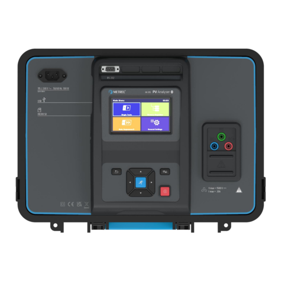
MI 3115 PV Analyser Instrument description 3 Instrument description Test connector options: Mains supply connector Serial port USB communication port MicroSD card slot Display... - Page 12 MI 3115 PV Analyser Instrument description Keypad ON/OFF key Test connector PE terminal DC- terminal DC+ terminal Protection cover P/S (probe) terminal...
-
Page 13: Instrument Operation
MI 3115 PV Analyser Instrument operation 4 Instrument operation The instrument can be manipulated via a keypad or touch screen. ON / OFF key Switch instrument on / off. To switch off the instrument press key for 2 s. The instrument automatically switches off after 10 minutes of idle state (no key pressed or any touch screen activity). -
Page 14: General Meaning Of Touch Gestures
MI 3115 PV Analyser Instrument operation Tap (briefly touch surface with fingertip) is used to: • Select appropriate option. • Confirm selected option. • Start and stop measurements. Swipe (press, move, lift) up/ down is used to: • Scroll content in same level. -
Page 15: Safety Checks, Symbols, Messages
MI 3115 PV Analyser Instrument operation Activates alphabetic characters. English keyboard layout. Greek keyboard layout. Russian keyboard layout. Returns to the previous menu without changes. Note • If Backspace is held for 2 s, all characters will be selected. Hint Long press on some keys opens additional keys. - Page 16 MI 3115 PV Analyser Instrument operation Time synchronization warning. After confirmation A 1785 PV Remote WL accepts time from instrument. Warning that time synchronization is not possible while remote unit is logging. Warning that STC / nominal values cannot be calculated and displayed, due to missing or invalid PV module or environmental data.
- Page 17 MI 3115 PV Analyser Instrument operation Measurement is running, consider displayed warnings. Warning! A very high and dangerous voltage is / will be present on the instrument output! The instrument automatically discharges tested object after finished insulation measurement. When an insulation resistance measurement...
-
Page 18: Bluetooth And Wi-Fi Connections
MI 3115 PV Analyser Instrument operation Test passed. Result is inside predefined limits. Test failed. Result is out of predefined limits. Measurement is aborted. Consider displayed warnings and messages. In R ISO PV and IEC 62446 Autotest function Roc calculation will only be performed, if the test time (duration) elapsed without the user stopping it. -
Page 19: Battery Indication
MI 3115 PV Analyser Instrument operation The terminal voltage monitor displays voltage and active test terminals indication. PE terminal should also be connected for correct input voltage condition. DC+ and PE are active test terminals. DC- and PE are active test terminals. -
Page 20: General Settings Menu
MI 3115 PV Analyser Instrument operation Single Test Menu for selecting single tests Auto Sequences® Menu for selecting Auto sequences Memory Organizer Menu for working with structured test objects and measurements General Settings Menu for setup of the instrument In the General Settings menu general parameters and settings of the instrument can be viewed or set. -
Page 21: Settings
MI 3115 PV Analyser Instrument operation Settings Setting different system and measuring parameters Bluetooth init. Bluetooth / Wi-Fi modul initialization Initial Settings Factory settings About Instrument data 4.6.1 Settings Touch screen Set Touch screen on / off. Keys & touch sound... -
Page 22: Wi-Fi Settings
MI 3115 PV Analyser Instrument operation 4.6.2 Wi-Fi settings Refer to chapter Communication with A 1785 PV Remote WL and A 1785 PV Remote WL Instruction manual for detailed information. 4.6.3 Bluetooth initialization In this menu internal Bluetooth / Wi-Fi module is reset. -
Page 23: About
MI 3115 PV Analyser Instrument operation 4.6.5 About In this menu instrument data (name, serial number, FW (firmware) and HW (hardware) version, profile code, HD (hardware documentation) version, and date of calibration) can be viewed. 4.6.6 User Accounts The instrument has a User Accounts system. Following actions can be managed: •... -
Page 24: Managing Accounts
MI 3115 PV Analyser Instrument operation User sign out: select Sign out Change user password (individual users can change their password): Select Change password, set new password. Account manager sign out: is automatic by exiting the Account manager menu. 4.6.7 Managing accounts User Accounts can be managed by the Account manager. -
Page 25: Instrument Profiles
MI 3115 PV Analyser Instrument operation The instrument uses specific system and measuring settings in regard to the scope of work or country it is used. These specific settings are stored in instrument profiles. By default, each instrument has at least one profile activated. Proper licence keys must be obtained to add more profiles to the instrument. - Page 26 Workspaces are stored on microSD card on directory PROJECTS, while Exports are stored on directory EXPORTS. Export files can be read by Metrel applications that run on other devices. Exports are suitable for making backups of important works or can be used for storage of works if the removable microSD card is used as a mass storage device.
-
Page 27: Auto Sequence® Groups
MI 3115 PV Analyser Instrument operation Import Import selected Export to a Workspace Delete Delete selected Export The Auto Sequences in the instrument can be organized by using lists. In a list a group of similar Auto Sequences is stored. The Auto Sequence® groups menu is intended to manage with different lists. -
Page 28: Pv Modules
MI 3115 PV Analyser Instrument operation 4.10 In this menu a list of PV modules and their data can be managed. The PV modules data from this list is used in measurements, for calculation of nominal and STC results. 4.10.1... -
Page 29: Import Of List Of Pv Modules
Serial resistance of PV module 4.10.3 Import of list of PV modules The list of PV modules can also be prepared in Metrel ES Manager and imported to the instrument. Refer to Metrel ES Manager Instruction manual for detailed information. -
Page 30: Memory Organizer
MI 3115 PV Analyser Memory Organizer 5 Memory Organizer Memory Organizer is an environment for storing and working with test data. The data is organized in a multilevel tree structure with Structure objects and Measurements. For a list of available structure objects see Appendix B - Structure objects. -
Page 31: Operations On Measurements
MI 3115 PV Analyser Memory Organizer 5.1.2 Operations on measurements Start Test Start a new measurement Clone Copy selected measurement as an empty measurement under the same Structure object Copy, Paste Copy a selected measurement as an empty measurement to... -
Page 32: Measurement Statuses
MI 3115 PV Analyser Memory Organizer 5.1.3 Measurement statuses Measurement statuses indicate the status of a measurement or a group of measurements in the Memory Organizer. Statuses of Single tests Passed finished single test with test results Failed finished single test with test results... -
Page 33: Operations On Structure Objects
MI 3115 PV Analyser Memory Organizer 5.1.4 Operations on Structure objects Start Test Start a new measurement (proceeds to menus for selection of measurement) Parameters View / edit parameters Add Measurement Add a new empty measurement. Menu for adding new measurement... -
Page 34: Changing Pv Modules And Other Parameters In Already Performed Measurements
MI 3115 PV Analyser Memory Organizer Header line (Workspace), Search Enter Search menu Search Search according to structure element name and status Clear filters Clear set filters in Search menu Operations on found structure objects Header line (Page x/y), Next Page,... - Page 35 MI 3115 PV Analyser Memory Organizer • Nominal and STC values will change accordingly. Measured data and environmental data will stay the same. After update is finished, confirmation with number of updated structures and measurements is displayed. All updated structures and measurements are saved automatically. Undo is not possible.
-
Page 36: Single Tests
MI 3115 PV Analyser Single tests 6 Single tests In single test main menu two modes for selecting single tests are available. Groups View groups of similar tests Last used View last made measurements In the Single test screens main measuring results, sub-results, limits and parameters of the measurement are displayed. -
Page 37: Single Test Start Screen
MI 3115 PV Analyser Single tests 6.2.1 Single test start screen Start test Start single test Parameters, or tap on Parameters field Set parameters/ limits of single test Prev Previous screen Next Next screen Calibrate Compensation of test leads (R low) -
Page 38: Single Test Result Screen
MI 3115 PV Analyser Single tests 6.2.3 Single test result screen Start test Start a new single test Save Save the result A new measurement was started from a The measurement will be saved under the Structure object in the structure tree... -
Page 39: Editing Graphs
MI 3115 PV Analyser Single tests 6.2.4 Editing graphs Options for editing graphs (start screen or after measurement is finished) Plot edit Open control panel for editing graphs y-range Up Increase scale factor for y-axis y-range Down Decrease scale factor for y-axis... -
Page 40: Single Test (Inspection) Start Screen
MI 3115 PV Analyser Single tests Overall status Options Status fields Child items Item 6.3.1 Single test (inspection) start screen Start test Start the inspection Help View help screens 6.3.2 Single test (Inspection) screen during test Header line (name of inspection),... -
Page 41: Single Test (Inspection) Result Screen
MI 3115 PV Analyser Single tests Hint Tap on or use key to set status. Rules for automatic applying of statuses The parent items will automatically • The fail status has highest priority. A fail get a status on base of statuses in... -
Page 42: Environmental Data
MI 3115 PV Analyser Single tests can select another Structure object or create a new Structure object. By pressing the Save key in Memory organizer menu the inspection is saved under selected location. An empty inspection was selected in The result(s) will be added to the inspection. -
Page 43: On-Line Synchronization Of Environmental Data Between Pv Remote Wl And Instrument
MI 3115 PV Analyser Single tests If the wireless connection is established between the PV remote WL and the instrument during the PV test the environmental data from the remote unit will be automatically sent to the instrument and considered in the test. -
Page 44: Synchronization Of Environmental Data Between Pv Remote Wl And Instrument After The Test
MI 3115 PV Analyser Single tests 6.4.2 Synchronization of environmental data between PV Remote WL and instrument after the test Following data are logged with PV remote WL and can be synchronized with the instrument later: Irradiance at time of measurement... -
Page 45: Manual Entry Of Environmental Data
MI 3115 PV Analyser Single tests • If PV Remote WL time is ahead of the displayed. • Once a PV measurement was updated with valid data from the PV Remote WL, further updates are not possible. Hint • It is recommended to perform automatic Date & time synchronization before start logging environmental data on PV solar field. -
Page 46: Single Test Measurements
MI 3115 PV Analyser Single tests Note • 6.5.1 Visual inspection Test results / sub-results Pass, Fail, Checked Test circuit 6.5.2 R low, 200 mA resistance measurement Test results / sub-results Resistance Result at positive test polarity Result at negative test polarity... -
Page 47: Compensation Of Test Leads
MI 3115 PV Analyser Single tests Test circuits 6.5.3 Compensation of test leads • Resistance of test lead(s) and cables can be compensated. Compensation is possible in R low function. Connection for compensating the resistance of test leads Procedure for compensation of test leads Select single test and its parameters. -
Page 48: Uoc/Isc
MI 3115 PV Analyser Single tests Test voltage Uoc_m Measured open-circuit voltage Test parameters Nominal test voltage Uiso [250 V, 500 V, 1000 V, 1500 V] Type of test Type Riso [Roc+, Roc-, Roc] Duration Duration [Off, 5 60 s]... - Page 49 MI 3115 PV Analyser Single tests Tcell (5 min) PV cell temperature 5 min before test Tcell (10 min) PV cell temperature 10 min before test Tcell (15min) PV cell temperature 15 min before test Tamb Ambient temperature at time of measurement or manual...
-
Page 50: I/U Curve
MI 3115 PV Analyser Single tests 6.5.6 I/U curve Test results / sub-results Uoc_m Measured open-circuit voltage Isc_m Measured short-circuit current Umpp_m Measured voltage (MPP) Impp_m Measured current (MPP) Pmpp_m Measured maximum power point Open-circuit voltage (STC) Short-circuit current (STC) - Page 51 MI 3115 PV Analyser Single tests Relative change of Isc ∆Isc Relative change of Umpp ∆Umpp Relative change of Impp ∆Impp Relative change of Pmpp ∆Pmpp Measured fill factor FF_m FF_n Fill factor (nominal) Graphs I/U (measured) Measured I/U curve...
-
Page 52: Automatic Measurement Iec 62446 Autotest
MI 3115 PV Analyser Single tests Test limit ∆Pmpp limit (∆Pmpp) High limit (∆Pmpp) [Off, Custom, 5 % 50 %] Test circuit 6.5.7 Automatic measurement IEC 62446 Autotest Test results / sub-results Roc+ Insulation resistance between DC+ and PE Roc-... -
Page 53: Environment
MI 3115 PV Analyser Single tests Duration Duration [5 s 60 s] Number of modules in PV Number of PV modules in series [Custom, 1 string Number of PV strings Number of PV modules / strings in parallel [Custom, 1... - Page 54 MI 3115 PV Analyser Single tests Irradiance at time of measurement Tcell PV cell temperature at time of measurement Tamb Ambient temperature at time of measurement Tcell (5 min) PV cell temperature 5 min before test Tcell (10 min) PV cell temperature 10 min before test...
-
Page 55: Auto Sequences
7 Auto Sequences® Auto Sequences® are pre-programmed sequences of measurements. The Auto Sequences can be pre-programmed on PC with the Metrel ES Manager software and uploaded to the instrument. On the instrument, parameters and limits of individual single test in the Auto Sequence can be changed / set. -
Page 56: Organization Of Auto Sequences® In Auto Sequences® Menu
MI 3115 PV Analyser Auto Sequences® 7.1.1 Organization of Auto Sequences® in Auto Sequences® menu The Auto Sequence® menu can be organized in a structural manner with folders, sub-folders and Auto Sequences. Auto Sequence in the structure can be the original Auto Sequence or a shortcut to the original Auto Sequence. -
Page 57: Auto Sequence® View Menu
MI 3115 PV Analyser Auto Sequences® 7.2.1 Auto Sequence® view menu Header is selected Auto Sequence name Description Options Single tests Header Start Test Start of Auto Sequence Single test is selected Auto Sequence name Parameters / limits of selected single test... -
Page 58: Indication Of Loops
MI 3115 PV Analyser Auto Sequences® Enable multiple points testing: set multiple points, see Managing multiple points. 7.2.2 Indication of Loops programmed. This means that the marked single test will be carried out as many times as the individual measurement. -
Page 59: Auto Sequence Result Screen
MI 3115 PV Analyser Auto Sequences® For the actual list and description of flow commands see Metrel ES Manager Software help file. The offered options in the control panel depend on the selected single test, its result and the programmed test flow. - Page 60 MI 3115 PV Analyser Auto Sequences® Description Status of single test Single tests Start Test Start a new Auto Sequence View View results of individual measurements. Comment Add comment to Auto Sequence Tap on Single test Viewing details of individual single tests, add...
-
Page 61: Maintenance
MI 3115 PV Analyser Maintenance 8 Maintenance It is essential that all measuring instruments are regularly calibrated in order for the technical specification listed in this manual to be guaranteed. We recommend an annual calibration. For repairs under or out of warranty please contact your distributor for further information. -
Page 62: Communications
• Tree structure from Metrel ES Manager PC software can be uploaded to the instrument. • PV module list from Metrel ES Manager PC software can be uploaded to the instrument. • Custom Auto Sequences® can be uploaded to the instrument or downloaded and stored to a PC. - Page 63 MI 3115 PV Analyser Communications Place instrument and PV Remote WL close to each other. Switch on both, the instrument and PV Remote WL to synchronize time. Date & time synchronization occurs automatically every time when instrument and PV Remote WL are switched on. If Remote time is ahead of the instrument s time, warning message is displayed.
-
Page 64: Technical Specifications
MI 3115 PV Analyser Technical specifications 10 Technical specifications 10.1 10.1.1 R ISO PV Insulation resistance General Nominal d.c. test voltages U ..... 250 V, 500 V, 1000 V, 1500 V Open-circuit voltage ......-0 % / +20 % of nominal voltage ... -
Page 65: R Low - 200 Ma Resistance Measurement
System voltage ........Maximum current ........20 A Maximum power of PV string ....24 kW Connection ..........standard 4 mm METREL safety banana jacks I-U curve tracking points ......min. 512 points (time equidistant) Sampling rate ......... Accuracy of STC values is based on accuracy of measured electrical quantities, accuracy of environmental parameters, and entered parameters of PV module. -
Page 66: Uoc/Isc Measurements
Maximum current ........20 A Maximum power of PV string ....24 kW Connection ..........standard 4 mm METREL safety banana jacks Accuracy of STC values is based on accuracy of measured electrical quantities, accuracy of environmental parameters, and entered parameters of PV module. See... -
Page 67: Environmental Parameters
MI 3115 PV Analyser Technical specifications DC current Range (A) Resolution (A) Accuracy 0.99 0.01 ±6 digits Isc_m 9.99 0.01 ±(1 % of reading + 3 digits) 10.00 19.99 0.01 ±1 % of reading The error in operating conditions could be at most the error for reference conditions ±2 % of measured value. - Page 68 MI 3115 PV Analyser Technical specifications RS232 ........... 1 port, DB9 female USB ............USB 2.0, standard Type-B Bluetooth ..........v4.2 BR/EDR and BLE specification Wi-Fi ............ 802.11 b/g/n (802.11n up to 150 Mbps) (Only for communication with A 1785 - PV Remote WL) Emission ..........
-
Page 69: Appendix A - Remote Operation
For more information contact Metrel or distributor. 11.3 SDK is a powerful interface for data communication with Metrel test instruments. The SDK itself is a set of subroutine definitions, protocols, and tools for building application software. It is intended for those who want to develop software using .NET platform and need to interface with Metrel instruments. -
Page 70: Appendix B - Structure Objects
MI 3115 PV Analyser Appendix B - Structure objects 12 Appendix B - Structure objects Symbol Default name Description Node Node Object Object Inverter PV inverter Combiner box PV Combiner box String PV string Module PV module... -
Page 71: Appendix C - Profile Notes
MI 3115 PV Analyser Appendix C - Profile Notes 13 Appendix C - Profile Notes So far there are no specific profile notes for this instrument. -
Page 72: Appendix D - Pv Measurements - Calculated Values
MI 3115 PV Analyser Appendix D - PV measurements - calculated values 14 Appendix D - PV measurements - calculated values Calculation to STC Measured voltage �� and current �� are calculated to STC as follows: �� �� �� ⋅ ( ��... - Page 73 MI 3115 PV Analyser Appendix D - PV measurements - calculated values �� = �� ∙ �� ������ ������,������ ������,������ Equation Instrument Description symbol abbreviation Umpp (STC) Maximum power point voltage calculated to STC �� ������,������ values Impp (STC) Maximum power point current calculated to STC ��...
- Page 74 MI 3115 PV Analyser Appendix D - PV measurements - calculated values Umpp (STC) Maximum power point voltage calculated to STC �� ������,������ values Impp (NOM) Nominal maximum power point current �� ������,������ Impp (STC) Maximum power point current calculated to STC ��...
- Page 75 MI 3115 PV Analyser Appendix D - PV measurements - calculated values �� �� ∙ �� ����,�� ����+ ����− �� ∙ ���� �� �� − �� ������ ����+ ����− Equation Instrument Description symbol abbreviation Roc+ Measured resistance between DC+ and PE ��...
- Page 76 MI 3115 PV Analyser Contacts METREL d.o.o. Ljubljanska cesta 77 SI-1354 Horjul Slovenia Phone: +386 (0)1 75 58 200 Fax: +386 (0)1 75 49 226 Email: info@metrel.si...
Need help?
Do you have a question about the MI 3115 PV and is the answer not in the manual?
Questions and answers