METREL EurotestCOMBO MI 3125 Instruction Manual
Hide thumbs
Also See for EurotestCOMBO MI 3125:
- Short instructions (24 pages) ,
- Instruction manual (60 pages) ,
- Instruction manual (64 pages)

Related Manuals for METREL EurotestCOMBO MI 3125


Summary of Contents for METREL EurotestCOMBO MI 3125
- Page 1 EurotestCOMBO MI 3125 MI 3125 BT Instruction manual Version 2.3.2, Code no. 20 751 484 Source document version: Version 2.3, Code no. 20 751 484...
- Page 2 (European Union) concerning safety and electromagnetic compatibility regulations © 2019 METREL The trade names Metrel, Smartec, Eurotest, Autosequence are trademarks registered or pending in Europe and other countries. No part of this publication may be reproduced or utilized in any form or by any means...
-
Page 3: Table Of Contents
MI 3125 / BT EurotestCOMBO Table of contents Table of contents Preface ........................7 Safety and operational considerations ..............8 Warnings and notes ..................8 Battery and charging ..................11 2.2.1 New battery cells or cells unused for a longer period ..........12 Standards applied ................... - Page 4 MI 3125 / BT EurotestCOMBO Table of contents Line impedance and prospective short-circuit current / Voltage drop ....46 5.6.1 Voltage drop ......................48 Earth resistance ....................50 PE test terminal ....................51 Data handling (model MI 3125 BT) ..............53 Memory organization ..................
- Page 5 MI 3125 / BT EurotestCOMBO Table of contents Fuse table – Impedances at 230 V a.c. (AS/NZS 3017) ........76 Appendix B - Accessories for specific measurements ........77 Appendix C – Country notes ................78 List of country modifications ................78 Modification issues ..................
-
Page 6: Preface
In order for operator to be familiar enough with performing measurements in general and their typical applications it is advisable to read Metrel handbook Guide for testing and verification of low voltage installations. The model MI 3125 BT has inbuilt Bluetooth interface for easy communication with PC and Android devices. -
Page 7: Safety And Operational Considerations
2.1 Warnings and notes In order to maintain the highest level of operator safety while carrying out various tests and measurements, Metrel recommends keeping your Eurotest instruments in good condition and undamaged. When using the instrument, consider the following general warnings: symbol on the instrument means »Read the Instruction manual... - Page 8 MI 3125 / BT EurotestCOMBO Safety and operational considerations Warnings related to measurement functions: Insulation resistance Insulation resistance measurement should only be performed on de-energized objects! Do not touch the test object during the measurement or before it is fully ...
- Page 9 MI 3125 / BT EurotestCOMBO Safety and operational considerations Continuity functions If voltages of higher than 10 V (AC or DC) is detected between test terminals, the continuity resistance test will not be performed. Before performing a continuity measurement, where necessary, compensate test ...
-
Page 10: Battery And Charging
If the instrument is not to be used for a long period of time, remove all batteries from the battery compartment. Alkaline or rechargeable Ni-Cd or Ni-MH batteries (size AA) can be used. Metrel recommends only using rechargeable batteries with a capacity of 2100 mAh or above. -
Page 11: New Battery Cells Or Cells Unused For A Longer Period
Ni-Cd cells can be subjected to these chemical effects (sometimes called the memory effect). As a result the instrument operation time can be significantly reduced during the initial charging/discharging cycles of the batteries. In this situation, Metrel recommend the following procedure to improve the battery lifetime: Procedure Notes Completely charge the battery. -
Page 12: Standards Applied
MI 3125 / BT EurotestCOMBO Safety and operational considerations 2.3 Standards applied The Eurotest instruments are manufactured and tested in accordance with the following regulations: Electromagnetic compatibility (EMC) Electrical equipment for measurement, control and laboratory use – EN 61326 EMC requirements Class B (Hand-held equipment used in controlled EM environments) Safety (LVD) EN 61010-1... -
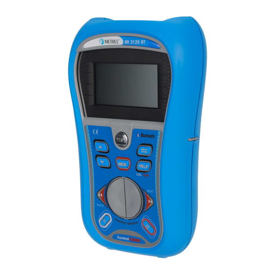
Page 13: Instrument Description
MI 3125 / BT EurotestCOMBO Instrument description 3 Instrument description 3.1 Front panel Figure 3.1: Front panel (picture of MI 3125 BT) Legend: * Model MI 3125 BT ** Model MI 3125 1 LCD 128 x 64 dots matrix display with backlight. 2 TEST Starts measurements. - Page 14 MI 3125 / BT EurotestCOMBO Instrument description Accesses help menus. In RCD Auto toggles between top and bottom parts of results 9* HELP / CAL field. Calibrates test leads in Continuity functions. Starts Z measurement in Voltage drop sub-function. Accesses help menus. HELP In RCD Auto toggles between top and bottom parts of results field.
-
Page 15: Connector Panel
MI 3125 / BT EurotestCOMBO Instrument description 3.2 Connector panel Figure 3.2: Connector panel (picture of MI 3125 BT) Legend: * Model MI 3125 BT ** Model MI 3125 Test connector Measuring inputs / outputs Protection cover Charger socket USB connector Communication with PC USB (1.1) port. -
Page 16: Back Side
MI 3125 / BT EurotestCOMBO Instrument description 3.3 Back side Figure 3.3: Back side Legend: Side belt Battery compartment cover Fixing screw for battery compartment cover Back panel information label Holder for inclined position of the instrument Magnet for fixing instrument close to tested item (optional) Figure 3.4: Battery compartment Legend: Battery cells... -
Page 17: Display Organization
MI 3125 / BT EurotestCOMBO Instrument description 3.4 Display organization Function name Result field Test parameter field Message field Terminal voltage Figure 3.5: Typical function monitor display Battery indication 3.4.1 Terminal voltage monitor The terminal voltage monitor displays on-line the voltages on the test terminals and information about active test terminals. -
Page 18: Result Field
MI 3125 / BT EurotestCOMBO Instrument description RCD tripped-out during the measurement (in RCD functions). Instrument is overheated. The measurement is prohibited until the temperature decreases under the allowed limit. Result(s) can be stored. (model MI 3125 BT) High electrical noise was detected during measurement. Results may be impaired. -
Page 19: Backlight And Contrast Adjustments
MI 3125 / BT EurotestCOMBO Instrument description Figure 3.6: Examples of help screens 3.4.7 Backlight and contrast adjustments With the BACKLIGHT key backlight and contrast can be adjusted. Click Toggles backlight intensity level. Locks high intensity backlight level until power is turned off or the Keep pressed for 1 s key is pressed again. -
Page 20: Instrument Set And Accessories
MI 3125 / BT EurotestCOMBO Instrument description 3.5 Instrument set and accessories 3.5.1 Standard set MI 3125 Instrument Short instruction manual Calibration Certificate Mains measuring cable Test lead.,3 x 1.5 m Test probe, 3 pcs ... -
Page 21: Instrument Operation
MI 3125 / BT EurotestCOMBO Instrument operation 4 Instrument operation 4.1 Function selection For selecting test function the FUNCTION SELECTOR shall be used. Keys: Select test / measurement function: <VOLTAGE TRMS> Voltage and frequency and phase sequence. <R ISO> Insulation resistance. ... -
Page 22: Settings
MI 3125 / BT EurotestCOMBO Instrument operation Settings Different instrument options can be set in the SETTINGS menu. All models: Selection of language, Setting the instrument to initial values, Selection of reference standard for RCD test, Entering Isc factor, ... -
Page 23: Language
MI 3125 / BT EurotestCOMBO Instrument operation 4.2.2 Language In this menu the language can be set. Figure 4.3: Language selection Keys: UP / DOWN Selects language. TEST Confirms selected language and exits to settings menu. Function selectors Exits back to main function menu. 4.2.3 Date and time (model MI 3125 BT) In this menu date and time can be set. - Page 24 MI 3125 / BT EurotestCOMBO Instrument operation Keys: UP / DOWN Selects standard. TEST Confirms selected standard. Function selectors Exits back to main function menu. Maximum RCD disconnection times differ in various standards. The trip-out times defined in individual standards are listed below. Trip-out times according to EN 61008 / EN 61009: ½I 2I...
-
Page 25: Isc Factor
MI 3125 / BT EurotestCOMBO Instrument operation ½I Standard 2I 5I N N N N EN 61008 / EN 61009 500 ms 500 ms 200 ms 150 ms IEC 60364-4-41 1000 ms 1000 ms 200 ms 150 ms BS 7671 2000 ms 500 ms 200 ms... -
Page 26: Initial Settings
MI 3125 / BT EurotestCOMBO Instrument operation Commander models A1314, A1401: new commanders (more information can be found in Appendix E) Note: Commander disabled is intended to disable the commander’s remote keys. In the case of high EM interfering noise the operation of the commander’s key can be irregular. - Page 27 MI 3125 / BT EurotestCOMBO Instrument operation R ISO No limit Utest = 500 V Low Ohm Resistance No limit R LOW CONTINUITY No limit Z - LINE Fuse type: none selected ΔU: 4.0 % VOLTAGE DROP : 0.00 Ω Z - LOOP Fuse type: none selected Test current: standard...
-
Page 28: Measurements
MI 3125 / BT EurotestCOMBO Measurements 5 Measurements 5.1 Voltage, frequency and phase sequence Voltage and frequency measurement is always active in the terminal voltage monitor. In the special VOLTAGE TRMS menu the measured voltage, frequency and information about detected three-phase connection can be stored. Phase sequence measurement conforms to the EN 61557-7 standard. - Page 29 MI 3125 / BT EurotestCOMBO Measurements Voltage measurement procedure * model MI 3125 BT Select the VOLTAGE TRMS function using the function selector switch. Connect test cable to the instrument. Connect test leads to the item to be tested (see figures 5.2 and 5.3). ...
-
Page 30: Insulation Resistance
MI 3125 / BT EurotestCOMBO Measurements 5.2 Insulation resistance The Insulation resistance measurement is performed in order to ensure safety against electric shock through insulation. It is covered by the EN 61557-2 standard. Typical applications are: Insulation resistance between conductors of installation, ... - Page 31 MI 3125 / BT EurotestCOMBO Measurements Insulation resistance measuring procedure * model MI 3125 BT Select the function using the function selector switch. Set the required test voltage. Enable and set limit value (optional). Disconnect tested installation from mains supply (and discharge insulation as ...
-
Page 32: Resistance Of Earth Connection And Equipotential Bonding
MI 3125 / BT EurotestCOMBO Measurements 5.3 Resistance of earth connection and equipotential bonding The resistance measurement is performed in order to ensure that the protective measures against electric shock through earth connections and bondings are effective. Two sub-functions are available: R LOWΩ... -
Page 33: R Lowω, 200 Ma Resistance Measurement
MI 3125 / BT EurotestCOMBO Measurements 5.3.1 R LOWΩ, 200 mA resistance measurement The resistance measurement is performed with automatic polarity reversal of the test voltage. Test circuit for R LOWΩ measurement Figure 5.9: Connection of 3-wire test lead plus optional extension lead Resistance to earth connection and equipotential bonding measurement procedure * model MI 3125 BT Select continuity function using the function selector switch. -
Page 34: Continuous Resistance Measurement With Low Current
MI 3125 / BT EurotestCOMBO Measurements Displayed result: R....R LOWΩ resistance. R+....Result at positive polarity R-....Result at negative test polarity 5.3.2 Continuous resistance measurement with low current In general, this function serves as standard -meter with a low testing current. The measurement is performed continuously without polarity reversal. -
Page 35: Compensation Of Test Leads Resistance
MI 3125 / BT EurotestCOMBO Measurements Displayed result: R....Resistance Notes: Continuous buzzer sound indicates that measured resistance PASS the limit. There is no sound if the limit is disabled (---). 5.3.3 Compensation of test leads resistance This chapter describes how to compensate the test leads resistance in both continuity functions, R LOWΩ... -
Page 36: Testing Rcds
MI 3125 / BT EurotestCOMBO Measurements 5.4 Testing RCDs Various test and measurements are required for verification of RCD(s) in RCD protected installations. Measurements are based on the EN 61557-6 standard. The following measurements and tests (sub-functions) can be performed: Contact voltage, ... -
Page 37: Contact Voltage (Rcd Uc)
MI 3125 / BT EurotestCOMBO Measurements Connections for testing RCD Figure 5.17: Connecting the plug commander and the 3-wire test lead 5.4.1 Contact voltage (RCD Uc) A current flowing into the PE terminal causes a voltage drop on earth resistance, i.e. voltage difference between PE equipotential bonding circuit and earth. -
Page 38: Trip-Out Time (Rcdt)
MI 3125 / BT EurotestCOMBO Measurements Contact voltage Uc RCD type Rated I N proportional to 1.05I N 21.05I N 30 mA A, F 1.41.05I N All models A, F 21.41.05I N < 30 mA A, F 21.05I N A, F 221.05I N... -
Page 39: Trip-Out Current (Rcd I)
MI 3125 / BT EurotestCOMBO Measurements Figure 5.19: Example of trip-out time measurement results Displayed results: t ... Trip-out time, Uc ..Contact voltage for rated I N 5.4.3 Trip-out current (RCD I) A continuously rising residual current is intended for testing the threshold sensitivity for RCD trip-out. -
Page 40: Rcd Autotest
MI 3125 / BT EurotestCOMBO Measurements Displayed results: I ... Trip-out current, Contact voltage at trip-out current I or end value in case the RCD didn’t trip, t ... Trip-out time. 5.4.4 RCD Autotest RCD autotest function is intended to perform a complete RCD test (trip-out time at different residual currents, trip-out current and contact voltage) in one set of automatic tests, guided by the instrument. - Page 41 MI 3125 / BT EurotestCOMBO Measurements Result examples: Step 1 Step 2 Step 3 Step 4 Step 5 Step 6 Step 7 Step 8 Figure 5.21: Individual steps in RCD autotest Bottom Figure 5.22: Two parts of result field in RCD autotest...
- Page 42 MI 3125 / BT EurotestCOMBO Measurements Displayed results: , IN, 0º), x1 ..Step 1 trip-out time ( , IN, 180º), x1 ..Step 2 trip-out time ( , 5IN, 0º), x5 ..Step 3 trip-out time ( , 5IN, 180º), x5 ..
-
Page 43: Fault Loop Impedance And Prospective Fault Current
MI 3125 / BT EurotestCOMBO Measurements 5.5 Fault loop impedance and prospective fault current Fault loop is a loop comprised by mains source, line wiring and PE return path to the mains source. The instrument measures the impedance of the loop and calculates the short circuit current. - Page 44 MI 3125 / BT EurotestCOMBO Measurements Fault loop impedance measurement procedure * model MI 3125 BT Select the Zloop Zs rcd sub-function using the function selector switch and / keys Select test parameters (optional). Connect test cable to the Eurotest Combo. ...
-
Page 45: Line Impedance And Prospective Short-Circuit Current / Voltage Drop
MI 3125 / BT EurotestCOMBO Measurements 5.6 Line impedance and prospective short-circuit current / Voltage drop Line impedance is measured in loop comprising of mains voltage source and line wiring. Line impedance is covered by the requirements of the EN 61557-3 standard. The Voltage drop sub-function is intended to check that a voltage in the installation stays above acceptable levels if the highest current is flowing in the circuit. - Page 46 MI 3125 / BT EurotestCOMBO Measurements Line impedance and prospective short circuit current Circuits for measurement of line impedance Figure 5.28: Phase-neutral or phase-phase line impedance measurement – connection of plug commander and 3-wire test lead Line impedance measurement procedure * model MI 3125 BT Select the Z-LINE...
-
Page 47: Voltage Drop
MI 3125 / BT EurotestCOMBO Measurements Input voltage range (L-N or L1-L2) (93 V U 134 V) 110 V (185 V U 266 V) 230 V (321 V U 485 V) 400 V Note: High fluctuations of mains voltage can influence the measurement results (the ... - Page 48 MI 3125 / BT EurotestCOMBO Measurements Step 1 - Zref Step 2 - Voltage drop Figure 5.31: Examples of voltage drop measurement result Displayed results: ΔU ... Voltage drop, .... Prospective short-circuit current, Z ....Line impedance at measured point, Zref ..
-
Page 49: Earth Resistance
MI 3125 / BT EurotestCOMBO Measurements 5.7 Earth resistance Earth resistance is one of the most important parameters for protection against electric shock. Main earthing arrangements, lightning systems, local earthings, etc can be verified with the earthing resistance test. The measurement conforms to the EN 61557- 5 standard. -
Page 50: Pe Test Terminal
MI 3125 / BT EurotestCOMBO Measurements Earth resistance measurements, common measurement procedure * model MI 3125 BT Select EARTH function using the function selector switch. Enable and set limit value (optional). Connect test leads to the instrument Connect the item to be tested (see Figure 5.33 and Figure 5.34). - Page 51 MI 3125 / BT EurotestCOMBO Measurements Examples for application of PE test terminal Figure 5.36: Reversed L and PE conductors (application of plug commander) Figure 5.37: Reversed L and PE conductors (application of 3-wire test lead) Reversed phase and protection conductors! The most dangerous situation! PE terminal test procedure Connect test cable to the instrument.
-
Page 52: Data Handling (Model Mi 3125 Bt)
MI 3125 / BT EurotestCOMBO Data handling 6 Data handling (model MI 3125 BT) 6.1 Memory organization Measurement results together with all relevant parameters can be stored in the instrument’s memory. After the measurement is completed, results can be stored to the flash memory of the instrument, together with the sub-results and function parameters. - Page 53 MI 3125 / BT EurotestCOMBO Data handling Data structure field Memory operation menu Data structure field level: OBJECT: Default location name (object and its successive number). 004: No. of selected element. level: BLOCK: Default location name (block and its successive number).
-
Page 54: Storing Test Results
MI 3125 / BT EurotestCOMBO Data handling 6.3 Storing test results After the completion of a test the results and parameters are ready for storing ( icon is displayed in the information field). By pressing the MEM key, the user can store the results. -
Page 55: Recalling Test Results
MI 3125 / BT EurotestCOMBO Data handling 6.4 Recalling test results Press the MEM key in a main function menu when there is no result available for storing or select MEMORY in the SETTINGS menu. Figure 6.3: Recall menu - installation Figure 6.4: Recall menu - measurements structure field selected field selected... -
Page 56: Clearing Stored Data
MI 3125 / BT EurotestCOMBO Data handling 6.5 Clearing stored data 6.5.1 Clearing complete memory content Select CLEAR ALL MEMORY in MEMORY menu. A warning will be displayed. Figure 6.6: Clear all memory Keys in clear all memory menu TEST Confirms clearing of complete memory content. -
Page 57: Clearing Individual Measurements
MI 3125 / BT EurotestCOMBO Data handling Keys in dialog for confirmation to clear results in selected location: HELP Deletes all results in selected location. TAB / MEM Exits back to delete results menu without changes. Function selector Exits back to main function menu without changes. TEST 6.5.3 Clearing individual measurements Select DELETE RESULTS in MEMORY menu. -
Page 58: Renaming Installation Structure Elements (Upload From Pc)
MI 3125 / BT EurotestCOMBO Data handling Figure 6.11: Display after measurement Figure 6.10: Dialog for confirmation was cleared 6.5.4 Renaming installation structure elements (upload from PC) Default installation structure elements are “Object”, “Block”, “Fuse” and “Connection”. In the PCSW package Eurolink-PRO default names can be changed with customized names that corresponds the installation under test. - Page 59 A new location name (scanned from a barcode label or a RFID tag) will be accepted by the instrument. A successful receive of the barcode or RFID tag is confirmed by two short confirmation beeps. Note: Use only barcode readers and RFID readers delivered by Metrel or authorized distributor.
-
Page 60: Communication (Model Mi 3125 Bt)
MI 3125 / BT EurotestCOMBO Data handling 6.6 Communication (model MI 3125 BT) Stored results can be transferred to a PC. A special communication program on the PC automatically identifies the instrument and enables data transfer between the instrument and the PC. There are three communication interfaces available: USB, RS 232 and Bluetooth. -
Page 61: Bluetooth Communication
Some Android applications automatically carry out the setup of a Bluetooth connection. It is preferred to use this option if it exists. This option is supported by Metrel's Android applications. If this option is not supported by the selected Android application then configure ... -
Page 62: Upgrading The Instrument
MI 3125 / BT EurotestCOMBO Upgrading the instrument 7 Upgrading the instrument The instrument can be upgraded from a PC via the RS232 communication port. This enables to keep the instrument up to date even if the standards or regulations change. The upgrade can be carried with help of a special upgrading software and the communication cable as shown on Figure 6.14. -
Page 63: Maintenance
MI 3125 / BT EurotestCOMBO Maintenance 8 Maintenance Unauthorized persons are not allowed to open the Eurotest Combo instrument. There are no user replaceable components inside the instrument, except the battery and fuse under rear cover. 8.1 Fuse replacement There is a fuse under back cover of the Eurotest Combo instrument. ... -
Page 64: Technical Specifications
MI 3125 / BT EurotestCOMBO Technical specifications 9 Technical specifications 9.1 Insulation resistance Insulation resistance (nominal voltages 50 V , 100 V and 250 V Measuring range according to EN61557 is 0.15 M 199.9 M. Accuracy Measuring range (M) Resolution (M) 0.00 ... -
Page 65: Continuity
MI 3125 / BT EurotestCOMBO Technical specifications 9.2 Continuity 9.2.1 Resistance R LOW Measuring range according to EN61557 is 0.16 1999 . Accuracy Measuring range R () Resolution () 0.00 19.99 (3 % of reading + 3 digits) 0.01 20.0 ... -
Page 66: Contact Voltage Rcd-Uc
MI 3125 / BT EurotestCOMBO Technical specifications IN × 1/2 IN × 1 IN × 2 IN × 5 RCD I AC A,F B,B+* AC B,B+* AC B,B+* AC A,F B,B+* AC A,F B,B+* IN (mA) 100 100 ... -
Page 67: Trip-Out Current
MI 3125 / BT EurotestCOMBO Technical specifications 9.3.4 Trip-out current Trip-out current Complete measurement range corresponds to EN 61557 requirements. Accuracy Measuring range I Resolution I 1.1I 0.1I 0.2I (AC type) 0.05I N N N N 1.5I 0.1I ≥30 mA) 0.2I... -
Page 68: Rcd Selected
MI 3125 / BT EurotestCOMBO Technical specifications 9.4.2 RCD selected Fault loop impedance Measuring range according to EN61557 is 0.46 9.99 k for I test = “Std” and 0.48 Ω 9.99 kΩ for I test = “Low”. Measuring range Resolution Accuracy... -
Page 69: Resistance To Earth
MI 3125 / BT EurotestCOMBO Technical specifications 321 V 266 V (45 Hz 65 Hz) Voltage drop (calculated value) Measuring range (%) Resolution (%) Accuracy 0.0 99.9 Consider accuracy of line impedance measurement(s)* measuring range……………………… 0.00 Ω 20.0 Ω *See chapter 5.6.2 Voltage drop for more information about calculation of voltage drop result. -
Page 70: Voltage
MI 3125 / BT EurotestCOMBO Technical specifications 9.7.2 Voltage Measuring range (V) Resolution (V) Accuracy 0 550 (2 % of reading + 2 digits) Result type ........True r.m.s. (trms) Nominal frequency range ....0 Hz, 14 Hz 500 Hz 9.7.3 Frequency Measuring range (Hz) Resolution (Hz) - Page 71 MI 3125 / BT EurotestCOMBO Technical specifications Maximum relative humidity ....95 %RH (0 C 40 C), non-condensing Storage conditions Temperature range ......-10 C +70 C Maximum relative humidity ....90 %RH (-10 C +40 C) 80 %RH (40 C ...
-
Page 72: A Appendix A - Fuse Table
MI 3125 / BT EurotestCOMBO Appendix A A Appendix A - Fuse table A.1 Fuse table - IPSC Fuse type NV Rated Disconnection time [s] current Min. prospective short- circuit current (A) 32.5 22.3 18.7 15.9 65.6 46.4 38.8 31.9 18.7 102.8 56.5... - Page 73 MI 3125 / BT EurotestCOMBO Appendix A 919.2 464.2 266.9 1217.2 821.7 663.3 319.1 1567.2 1133.1 964.9 836.5 447.9 2075.3 1429 1195.4 1018 585.4 Fuse type B Rated Disconnection time [s] current Min. prospective short- circuit current (A) Fuse type C Rated Disconnection time [s] current...
- Page 74 MI 3125 / BT EurotestCOMBO Appendix A Fuse type D Rated Disconnection time [s] current Min. prospective short- circuit current (A) 10.8 21.6 32.4 70.2 86.4 172.8...
-
Page 75: Fuse Table - Impedances At 230 V A.c. (As/Nzs 3017)
MI 3125 / BT EurotestCOMBO Appendix A A.2 Fuse table – Impedances at 230 V a.c. (AS/NZS 3017) Type B Type C Rated Disconnection time [s] Rated Disconnection time [s] current current Max. loop impedance () Max. loop impedance () 9.58 5.11 5.75... -
Page 76: B Appendix B - Accessories For Specific Measurements
MI 3125 / BT EurotestCOMBO Appendix B B Appendix B - Accessories for specific measurements The table below presents standard and optional accessories required for specific measurement. The accessories marked as optional may also be standard ones in some sets. Please see attached list of standard accessories for your set or contact your distributor for further information. -
Page 77: C Appendix C - Country Notes
MI 3125 / BT EurotestCOMBO Appendix C C Appendix C – Country notes This appendix C contains collection of minor modifications related to particular country requirements. Some of the modifications mean modified listed function characteristics related to main chapters and others are additional functions. Some minor modifications are related also to different requirements of the same market that are covered by various suppliers. -
Page 78: At Modification - G Type Rcd
MI 3125 / BT EurotestCOMBO Appendix C C.2.1.1 Modification of Appendix A In addition to fuse data given in Appendix A gR fuses are added. Fuse type gR Rated Disconnection time [s] current Min. prospective short- circuit current (A) 31.4 62.8 94.2 32.5... -
Page 79: No, Dk, Sw Modification - It Supply System
MI 3125 / BT EurotestCOMBO Appendix C Test parameters for RCD test and measurement TEST RCD sub-function test [RCDt, RCD I, AUTO, Uc]. I Rated RCD residual current sensitivity I [10 mA, 30 mA, 100 mA, 300 N mA, 500 mA, 1000 mA]. type RCD type AC, A, F, B*, B+* starting polarity [ * ],... -
Page 80: Aus / Nz Modification - Fuse Types According To As/Nzs 3017
MI 3125 / BT EurotestCOMBO Appendix C C.2.3.2 New chapter For selection of proper supply system, the chapter 4.2.9 is added. 4.2.9. Supply earthing system In this menu the tested supply system can be selected. Figure 4.9: Selection of supply system Keys: UP / DOWN Selects distribution supply system. - Page 81 MI 3125 / BT EurotestCOMBO Appendix C Keys: UP / DOWN Sets Z value. TEST Confirms Z value. Function selectors Exits back to main function menu. The impedance limit values for different overcurrent protective devices depend on nominal voltage and are calculated using the Z factor. Z factor 1.00 is used for nominal voltage 230 V and Z factor 1.04 is used for nominal voltage 240 V.
- Page 82 MI 3125 / BT EurotestCOMBO Appendix C scalling_factor ..Correction factor for Isc (set to 1.00). Input voltage range (L-PE) (93 V U 134 V) 110 V L-PE (185 V U 266 V) 230 V L-PE Modifications of the chapter 5.6 Modified test parameters for line impedance measurement Fuse type...
-
Page 83: D Appendix D - It Supply Systems
D Appendix D - IT supply systems In order for operator to be familiar enough with measurements in and their typical applications in IT supply system it is advisable to read Metrel handbook Measurements on IT power supply systems. D.1 Standard references EN 60364-4-41, EN 60364-6, EN 60364-7-710, BS 7671 D.2 Fundamentals... - Page 84 MI 3125 / BT EurotestCOMBO Appendix D MI 3125 / MI 3125 BT test functions and IT systems The table below contains functions of the instrument including compatibility notes related to the IT system. IT system functions Note Voltage Symbols modified for IT system, see figure D.2. Voltage Phase rotation For three phase system only, automatic detection.
- Page 85 MI 3125 / BT EurotestCOMBO Appendix D RCD testing RCD testing is performed in the same way as in TN/TT system (See chapter 5.4), with the following exception: measurement is relevant only in case of first fault. Test circuit with bypassing principle should correspond to that on figure D.3. Figure D.3: RCD testing in IT system with bypassing RC...
-
Page 86: E Appendix E - Commanders (A 1314, A 1401)
If the commander is not used for a long period of time, remove all batteries from the battery compartment. Alkaline or rechargeable Ni-MH batteries (size AA) can be used. Metrel recommends only using rechargeable batteries with a capacity of 800 mAh or above. -
Page 87: Operation Of Commanders
MI 3125 / BT EurotestCOMBO Appendix E Figure E.2: Front side plug commander (A 1314) Figure E.3: Back side Legend: 1 TEST Starts measurements. TEST Acts also as the PE touching electrode. 2 LED Left status RGB LED 3 LED Right status RGB LED 4 LEDs Lamp LEDs (Tip commander) - Page 88 MI 3125 / BT EurotestCOMBO Appendix E Left LED orange Voltage between any test terminals is higher than 50 V Both LEDs blink red Low battery Both LEDs red and switch off Battery voltage too low for operation of commander PE terminal test procedure Connect commander to the instrument.
Need help?
Do you have a question about the EurotestCOMBO MI 3125 and is the answer not in the manual?
Questions and answers