SystemAir IV Smart EC Installation And Operating Instructions Manual
Jet fan
Hide thumbs
Also See for IV Smart EC:

Related Manuals for SystemAir IV Smart EC


Summary of Contents for SystemAir IV Smart EC
- Page 1 Jet fan - IV Smart EC, IV Smart EC Modbus Installation and Operating Instructions...
- Page 2 © Copyright Systemair All rights reserved Systemair reserves the rights to alter their products without notice. This also applies to products already ordered, as long as it does not affect the previously agreed specifications. 498198...
-
Page 3: Table Of Contents
8.3.1 Internal motor protections .......... 11 Motor controls .............. 12 Field connections ............12 8.5.1 IV Smart EC Connection diagram ....... 12 8.5.2 IV Smart EC Control options ........13 8.5.3 IV Smart EC - Modbus Connection diagram ..... 14 498198... -
Page 4: General Information
IV Smart EC / Modbus General information Notice Symbols Danger Direct hazard Failure to comply with this warning will lead directly to death or serious injury. Warning Potential hazard Failure to comply with this warning may lead to death or serious injury. -
Page 5: Personnel
◊ Cover or restrict adjacent live parts Warranty The sole warranty applicable to the products described herein is the Systemair Limited Warranty set forth within our website www. Systemair.com on the product specific webpage in the Documents tab (“Limited Warranty”). -
Page 6: Delivery
◊ Do not walk under suspended loads. ◊ Make sure that there is nobody under a suspended load. Delivery Each fan leaves Systemair in proper mechanical and electrical condition. The fan should remain in the original packaging until the final delivery to the installation site. 4.2.1... -
Page 7: Description
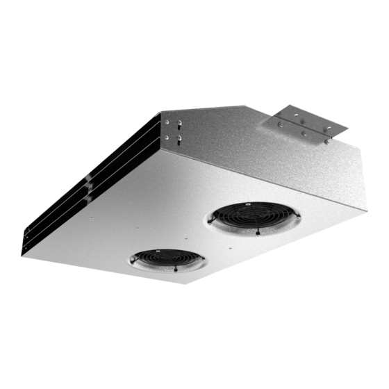
5.1.1 IV Smart EC The IV Smart EC is a centrifugal jet fan driven by two EC motors, which can be controlled via an analog 0-10V signal, PWM signal, or jumpered to run at full speed. 5.1.2 IV Smart EC - Modbus The IV Smart EC - Modbus is a centrifugal jet fan driven by two EC motors which can be controlled via a digital Modbus signal. -
Page 8: Dimensions
27-13/16 22-3/8 Nameplate The following nameplate is shown as an example of formatting. The shown image is for the IV Smart EC model specifically. Note: Variation in the current draw of an Electronically Commutated Motor can be expected, which is dependent on the line impedance. -
Page 9: Installation
IV Smart EC / Modbus Installation Safety information Warning Danger from falling fan or fan parts. Check the surface before installation for load bearing capacity. ◊ Installation may only be carried out by adequately qualified persons, see Table 1: Qualifications ◊... -
Page 10: Vibration Dampers
IV Smart EC / Modbus Mounting to concrete: ◊ If using Post-Installed Mechanical Anchors (expansion or undercut), anchors must be tested and evaluated to ACI 355.2 require- ments. ◊ If using Post-Installed Mechanical Anchors (Adhesive), anchors must be tested and evaluated to ACI 355.4 requirements. -
Page 11: Electrical Connection
◊ Motor current limitation ◊ Soft start ◊ Thermal overload protection ◊ Line undervoltage detection The IV Smart EC - Modbus motors have the following inherent electronic protections: ◊ Power limitation ◊ Motor current limitation ◊ Soft-start ◊ Overvoltage detection ◊... -
Page 12: Motor Controls
◊ The IV Smart EC fan is controlled via an analog PWM or 0-10V signal. ◊ The IV Smart EC Modbus is controlled by digital Modbus communications. Each motor must be individually addressed on the job site. Each motor in the fan (quantity 2 per fan) comes with a default Modbus address of “1” from the factory. Accessories are offered to enable enhanced communication methods such as BACnet communication for the Modbus fan. -
Page 13: Iv Smart Ec Control Options
Control Options IV Smart EC IV Smart EC / Modbus 8.5.2 IV Smart EC Control Options *AS IS Maximum Speed Typical Remote Potentiometer Use a small flat-head screwdriver to remove red jumper Pre-Installed Jumper Placed from +10V to 0-10V Jumper... -
Page 14: Iv Smart Ec Modbus Connection Diagram
“EBM – Auto Addressing” on the Systemair Website. • Modbus addresses, registers, and instructions can be found in the document titled “EBM – Modbus Manual” on the Systemair Website. • Each motor must be individually addressed on the jobsite. Each motor in the fan (quantity 2 per fan) comes with a default Modbus address of “1”... -
Page 15: Residual Current Circuit Breaker
IV Smart EC / Modbus Residual current circuit breaker ◊ All-current-sensitive residual current circuit breakers are required for use in alternating-current systems with 50/60 Hz, in combina- tion with electronic devices such as EC motors, frequency converters or uninterruptible power supplies (UPS). -
Page 16: Preconditions
Table 4: Troubleshooting Problem Possible causes Remedy Fan does not run smoothly Impeller imbalance Rebalancing by a specialist , otherwise contact Systemair Soiling on the rotor Clean carefully, rebalance Material decomposition on the Contact Systemair rotor due to aggressive material... -
Page 17: Maintenance
IV Smart EC / Modbus 11.3 Maintenance As set forth in the Limited Warranty, warranty claims can only be made if maintenance work is carried out correctly and written evidence thereof is provided. We recommend regular maintenance intervals to ensure continuous fan operation. These maintenance intervals are specified in the “Activities”... -
Page 18: Variable Speed Fans
◊ If no damage occurs, adjust the maintenance intervals up to those stated in the operating instructions. ◊ Responsibility for gradual adaptation is with the system operator/installer. 11.5 Replacement parts ◊ Replacement parts must be installed by a Systemair representative and a UL witness in order to maintain the UL Safety Listing. Cleaning 12.1 Safety information ◊... -
Page 19: Commissioning Report
IV Smart EC / Modbus Commissioning Report Please keep the completed commissioning report in a safe place. As set forth in the Limited Warranty, in the case of a warranty claim, this report can be requested by Systemair. Description: Article no.: Manufacturing order no.:... -
Page 20: Usa Declaration Of Conformity
Please keep the completed commissioning report in a safe place. In the case of a warranty claim, this report can be requested by Systemair. For technical questions, please contact the technical support division of Systemair. USA Declaration of Conformity Manufacturer: Systemair Mfg. - Page 21 IV Smart EC / Modbus 498198...
- Page 22 IV Smart EC / Modbus 498198...
- Page 23 IV Smart EC / Modbus 498198...
- Page 24 © Copyright Systemair All rights reserved Systemair reserves the rights to alter their products without notice. This also applies to products already ordered, as long as it does not affect the previously agreed specifications.
Need help?
Do you have a question about the IV Smart EC and is the answer not in the manual?
Questions and answers