Table of Contents
Advertisement
Quick Links
Advertisement
Table of Contents

Related Manuals for SystemAir IV-50 EC


Summary of Contents for SystemAir IV-50 EC
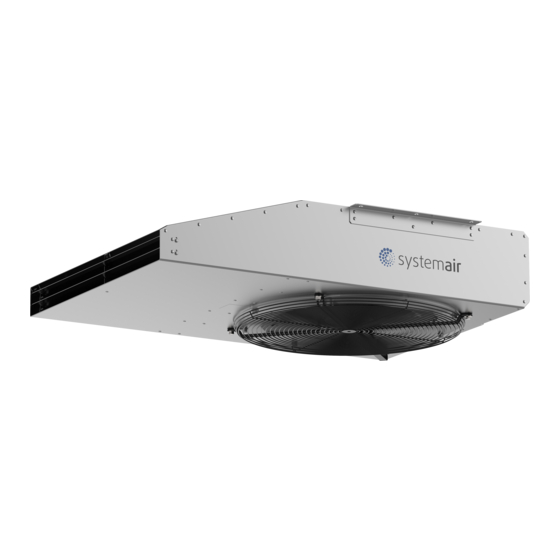
- Page 1 IV-50 EC Jet fan Installation and Operating Instructions...
- Page 2 © Copyright Systemair All rights reserved Systemair reserves the rights to alter their products without notice. This also applies to products already ordered, as long as it does not affect the previously agreed specifications. 499231...
-
Page 3: Table Of Contents
Contents General information ..............4 Commissioning ................13 Notice symbols .............. 4 Safety information ............13 1.1.1 Instruction symbols ........4 Preconditions ..............13 Safety notes ................4 Tests ............... 13 Personnel ................ 5 Operation ................... 13 Personal protective equipment ........5 10.1 Safety information ............ -
Page 4: General Information
IV-50 EC General information Notice Symbols Danger Direct hazard Failure to comply with this warning will lead directly to death or serious injury. Warning Potential hazard Failure to comply with this warning may lead to death or serious injury. Caution Hazard with a low risk Failure to comply with this warning may lead to moderate injuries. -
Page 5: Personnel
For the assertion of warranty claims, the products must be correctly connected and operated and used in accordance with the datasheets. Further prerequisites are a completed maintenance plan with no gaps and a commissioning report. Systemair will require these in the case of a warranty claim. The commissioning report is a component at the end of this manual. The maintenance plan must be implemented by the installer or building operations team. -
Page 6: Delivery
◊ Do not walk under suspended loads. ◊ Make sure that there is nobody under a suspended load. Delivery Each fan leaves Systemair in proper mechanical and electrical condition. The fan should remain in the original packaging until the final delivery to the installation site. 4.2.1... -
Page 7: Description
◊ Turn the impeller at least 10 revolutions, once per month. o Please ensure that the impeller is at a different position afterward. Storage for more than 12 months: ◊ Contact Systemair. We recommend an inspection by Systemair or its representative before commissioning. Description General ◊... -
Page 8: Dimensions
Dimensions are in inches (mm) Nameplate and type key Nameplate The following nameplate is shown as an example of formatting. The shown image is for the IV-50 EC model specifically. Note: Variation in the current draw of an Electronically Commutated Motor can be expected, which is dependent on the line impedance. -
Page 9: Installation
IV-50 EC Installation Safety information Warning Danger from falling fan or fan parts. ◊ Check the surface before installation for load-bearing capacity. ◊ Consider all static and dynamic loads when selecting hoisting equipment and fastening components. ◊ Installation may only be carried out by adequately qualified persons, see Table 1: Qualifications ◊... -
Page 10: Vibration Dampers
IV-50 EC o If using Post-Installed Mechanical Anchors (Adhesive), anchors must be tested and evaluated to ACI 355.4 requirements. ◊ If you are mounting to steel or wood frames, you must use vibration isolators. Anchoring: ◊ Contractor to anchor suspended unit to concrete with (1) 3/8-inch diameter concrete anchor capable of resisting 40 lbs (Safety Factor of 4 equals 160 lbs) of tension load with minimum embedment of 2-inch at each of the (4) support points. -
Page 11: Electrical Connection
IV-50 EC Electrical connection Safety information Warning Danger from electrical voltage. ◊ Observe the 5 rules of electrical safety, see 2.3 Five rules of electrical safety. ◊ Prevent the ingress of water into the connection box. ◊ The electrical connection must be carried out by qualified persons, see Table 1: Qualifications. -
Page 12: Motor Controls
◊ Option 1 is the factory setting ◊ Contact Systemair if you wish to use a lower maximum fan speed than factory default without variable speed control. ◊ To activate Option 2, variable speed control, do the following three steps: 1. -
Page 13: Residual Current Circuit Breaker
IV-50 EC Table 3: Speed reference Signal Type Condition Resulting Frequency Value Conductors Speed = 0 Zero (output voltage 4.8V) Frequency White Black (speed reference) Speed > 0 Speed (rpm) x 0.6015 Residual current circuit breaker ◊ All-current-sensitive residual current circuit breakers are required for use in alternating-current systems with 50/60 Hz, in combina- tion with electronic devices such as EC motors, frequency converters or uninterruptible power supplies (UPS). -
Page 14: Preconditions
Table 4: Troubleshooting Problem Possible causes Remedy Fan does not run smoothly Impeller imbalance Rebalancing by a specialist , otherwise contact Systemair Soiling on the rotor Clean carefully, rebalance Material decomposition on the Contact Systemair rotor due to aggressive material... - Page 15 Fault On Time Off Time Interval Time (off) Under voltage 0.1 sec 0.1 sec Overload / Over current Overvoltage 0.25 sec 0.25 sec 2 sec Communication timeout Watchdog timeout Locked rotor Note: For all other damage/defects, please contact Systemair. 499231...
-
Page 16: Maintenance
IV-50 EC 11.3 Maintenance Warranty claims can only be made if maintenance work is carried out correctly and written evidence thereof is provided. We recommend regular maintenance intervals to ensure continuous fan operation. These maintenance intervals are specified in the “Activities”... -
Page 17: Variable Speed Fans
◊ Check the condition of the shaft sealing rings and shaft bearings and take action if necessary. 11.6 Replacement parts ◊ Replacement parts must be installed by a Systemair representative and a UL witness in order to maintain the UL Safety Listing. Cleaning 12.1 Safety information ◊... -
Page 18: Commissioning Report
IV-50 EC Commissioning Report Description: Article no.: Manufacturing order no.: Installer Company: Contact person: Company address: Tel. no.: Email: Operator (Place of installation) Company: Contact person: Company address: Tel. no.: Email: Type of connection □ □ Directly on line 0-10V... -
Page 19: Usa Declaration Of Conformity
Please keep the completed commissioning report in a safe place. In the case of a warranty claim, this report can be requested by Systemair. For technical questions, please contact the technical support division of Systemair. USA Declaration of Conformity Manufacturer: Systemair Mfg. - Page 20 © Copyright Systemair All rights reserved Systemair reserves the rights to alter their products without notice. This also applies to products already ordered, as long as it does not affect the previously agreed specifications.
Need help?
Do you have a question about the IV-50 EC and is the answer not in the manual?
Questions and answers