SystemAir IV Smart AC Installation And Operating Instructions Manual
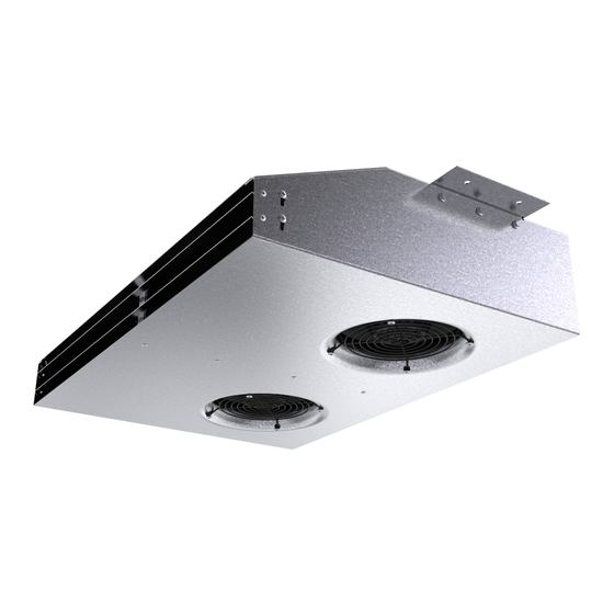
Jet fan
Hide thumbs
Also See for IV Smart AC:

Related Manuals for SystemAir IV Smart AC


Summary of Contents for SystemAir IV Smart AC
- Page 1 Jet fans IV Smart AC, IV Smart EC, IV Smart EC CO Installation and Operating Instructions Document in original language | · 005...
- Page 2 © Copyright Systemair AB All rights reserved E&OE Systemair AB reserves the rights to alter their products without notice. This also applies to products already ordered, as long as it does not affect the previously agreed specifications. | 005...
-
Page 3: Table Of Contents
Terminal boxes ........6 Name plate and type key ........6 Installation.............6 Installation on the ceiling ......7 Electrical connection ........7 Wiring diagram IV Smart AC ......7 Wiring diagram IV Smart EC ......8 Wiring IV Smart EC-CO ......9 8.3.1 Fan speed specification ..... 10 Protecting the motor...... -
Page 5: General Information
General information | General information Warning symbols Danger Caution Hazard with a low risk Direct hazard Failure to comply with this warning may lead to Failure to comply with this warning will lead moderate injuries. directly to death or to serious injury. Important Warning Hazard with risk of damage to objects... -
Page 6: Warranty
Further prerequisites are a completed maintenance plan with no gaps and a commissioning re- port. Systemair will require these in the case of a warranty claim. The commissioning report is a component of this document. The maintenance plan must be created by the operator, see section Maintenance. -
Page 7: Description Iv Smart
Description IV Smart | Unpacking When opening the transport packaging, there is a risk of damage from sharp edges, nails, staples, splinters etc. ♦ Unpack the fan carefully. ♦ Check the fan for obvious transport damage. ♦ Only remove the packaging shortly before assembly. Transport Safety information Warning: Electrical or mechanical hazards due to fire, moisture, short circuit or malfunction. -
Page 8: Description - Different Types
Description — different types IV Smart EC The fan is driven by two EC motors. IV Smart AC The fan is driven by two AC motors. IV Smart EC—CO — equipped with a carbon monoxide control unit The fan is driven by two EC motors (see “IV Smart EC equipped with an EC motor”). The fan and the control unit are pre —wired and ready for use. -
Page 9: Information On The Effects Of Co On Humans
Description IV Smart | Information on the effects of CO on humans Warning This CO control unit is designed to protect people from the acute effects of carbon monoxide. It cannot prevent the chronic effects of carbon monoxide exposure. The CO control unit can not fully protect people at special risk, such as those with particular medical conditions. -
Page 10: Terminal Boxes
| Name plate and type key Terminal boxes IV Smart AC IV Smart EC IV Smart CO Name plate and type key Type designation Insulation class Voltage/current/frequency Article number/production number/manufacturing date Input power Certifications Enclosure class/fan impeller speed/ weight Table 4 Type key... -
Page 11: Installation On The Ceiling
All-current-sensitive residual current circuit breakers are required for use in alternating-current systems with 50/60 Hz, in combination with electronic devices such as EC motors, frequency converters or uninterruptible power supplies (UPS). Wiring diagram IV Smart AC Color Function/pin assignment Black Power supply 230 V AC, 50...60 Hz... -
Page 12: Wiring Diagram Iv Smart Ec
| Electrical connection Wiring diagram IV Smart EC The connection cables of the two motors of the IV Smart are carried out in the terminal boxes. black black blue Terminal box — Power supply blue green/yellow green/yellow + 10 V yellow 0–10 V yellow... -
Page 13: Wiring Iv Smart Ec-Co
Electrical connection | CON11 blue Neutral conductor green/yellow CON12 GND-connection yellow Controller input 0...10 V or PWM 0...10 V PWM Speed output: Open Collector, 1 impulse per revolution, Tacho white electrically isolated, Isink_max = 10 mA Voltage output 10 V, Imax. 10 mA, short-circuit-proof, 10 V power supply for external devices. -
Page 14: Fan Speed Specification
| Commissioning Electrical connections cont'd 1. 24 V Connection for CO sensor supply connection and measuring signal 2. 4-20 mA X6 SENSOR connection 3. EARTH 1. NC Potential-free alarm contact connection option for controlling an 2. COM X7 ALARM alarm siren or other auxiliary device. 3. -
Page 15: Tests When Activated Ec Co Version
Operation | Tests Do the tests requested in the commissioning report (15 Commissioning Report, page 15) Tests when activated EC CO version 9.1.1 Function test A function test is carried out once the voltage supply is connected, with the displays, the potential-free contact and the fans being switched on briefly. -
Page 16: Control Unit
Check if the correct fan is used for your application. Note: For all other damage/defects, please contact Systemair. 11.2 Alarm and fault handling Carbon monoxide control unit The control unit continuously monitors the sensor's function, as well as the function of the fans. The following sub- points describe the the meaning of the fault and CO-Alarm display and the way in which they should be responded to. -
Page 17: Maintenance
1-2 and call the emergency gas services (please check you have their number now) and if necessary notify the relevant gas fitter. - Fan failure Contact Systemair Fault - Sensor fault 11.3 Maintenance Warranty claims can only be made if maintenance work is carried out correctly and written evidence thereof is provided. -
Page 18: Cleaning
Check the flexible connectors for damage. See normal operating conditions Spare parts ♦ Use original spare parts from Systemair only. ♦ When ordering spare parts, please specify the serial number of the fan. This can be found on the name plate. Cleaning Safety information ♦... -
Page 19: Commissioning Report
Commissioning Report | Commissioning Report Warranty claims can only be made if commissioning work is carried out correctly and written evidence thereof is provided. Description: Article no.: Manufacturing order no.: Installer Company: Contact person: Company address: Tel. no.: Email: Operator (Place of installation) Company: Contact person: Company address:... - Page 20 | Commissioning Report Fan impeller speed [rpm]: Current L1 [A]*: Current L2 [A]: “Air volume”, “Differential pressure” not necessary for Jet fans Air volume [m3/s]: Current L3 [A]: Differential pressure [Pa]*: *For single-phase fans, fill in line “Current L1 [A]” *Δ- Pressure between suction-side and discharge of the fan If an air flow measurement is not possible, this value can be calculated using the following formula: Flow speed [m/s]...
- Page 21 | 005...
- Page 22 Systemair GmbH Seehöfer Str. 45 97944 Boxberg Germany Tel.: +49 (0)7930/9272-0 Fax: +49 (0)7930/9273-92 info@systemair.de www.systemair.de...
Need help?
Do you have a question about the IV Smart AC and is the answer not in the manual?
Questions and answers