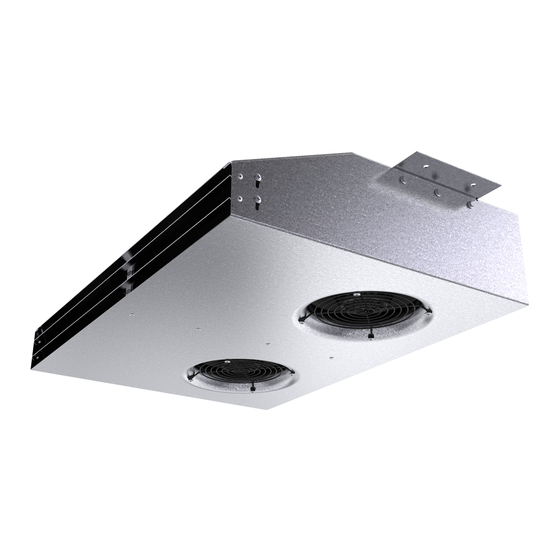
SystemAir IV Smart AC Installation,Operation And Maintenance Instruction
Centrifugal induction fan
Hide thumbs
Also See for IV Smart AC:
- Installation and operating instructions manual (52 pages) ,
- Installation and operating instructions manual (36 pages) ,
- Installation and operating instructions manual (24 pages)

Related Manuals for SystemAir IV Smart AC


Summary of Contents for SystemAir IV Smart AC
- Page 1 Installation, Operation and Maintenance instruction IV Smart Centrifugal induction fan AC IV Smart Centrifugal induction fan EC IV Smart Centrifugal induction fan EC CO...
-
Page 2: Table Of Contents
Table of content 1 Introduction ............1 10.1 To disassemble and discard the parts of the product............ 11 Product description ........1 Intended use ..........1 11 Warranty ............11 Document description........1 12 Technical data ........... 12 Product overview......... 1 12.1 Technical data overview ...... -
Page 3: Introduction
The IV Smart fans are applicable for installation indoors in underground or aboveground garages. The product is Product overview Casing Mounting bracket Fan impeller Motor Connection box (IV Smart AC and IV Smart EC CO has 1 single connection box) Name plate... -
Page 4: Name Plate
Information that is necessary in a given situation. Safety instructions Warning Read the warning instructions that follow before you do work on the product. Operate a mobile device to scan the scannable code and go to the Systemair documentation portal for more documentation and document translations. -
Page 5: Personal Protective Equipment
–10 and +30 °C. A stable ambient • Sound levels exceeding 70 dB(A) may occur depending temperature prevents damage from condensation. on model and size. Visit www.systemair.com for more de- tailed information about your product. • Keep the product in storage for maximum 1 year. -
Page 6: Installation
CO concen- to the inner ceiling with 4 screws. The product can also tration level. be installed in the ceiling using pendulum bars or wires. Pendulum bars and wires are not supplied by Systemair. 4.3.3 The automatic fan speed control function... -
Page 7: Fault Alarm Function
Fault alarm is Fan or power Contact active supply is out of Systemair function (alarm triggers after 10 seconds) Short circuit or Contact break in sensor Systemair cable (alarm trig-... -
Page 8: Electrical Connection
To install motor protection for Electrical connection AC motors To do before the electrical • If the product has an built in motor protection, reset by dis- connection connecting the product from power for 60 seconds. • If the motor has temperature monitors such as thermal •... -
Page 9: Commissioning
To start a product with an AC motor The commissioning report is found at www.systemair.com. Set the installed safety switch in the ON position. To do before the Install the external speed controller. Refer to the instruc- tion manual for the installed speed controller. -
Page 10: Maintenance
• For information about spare parts, send an e-mail to Caution support@systemair.com. • Do not clean the product with a high- • For more information about spare parts, contact Systemair pressure washer. support. • Do not clean the product with steel •... -
Page 11: Troubleshooting
Troubleshooting Note: If you cannot find a solution to your problem in this section, speak to Systemair technical support. Problem Cause Solution The fan impeller is not correctly Speak to Systemair technical support. balanced. There is dirt on the fan impeller. - Page 12 This is not applicable for EC motors or 3–phase AC motors. There is blockage in the motor. Speak to Systemair technical support. Defective motor winding. If it is possible, measure the resistance to do a check of the motor winding.
-
Page 13: Disposal
For warranty claims, send a written maintenance plan and product or the packaging of the product shows that this the commissioning report to Systemair. The warranty is only product is not domestic waste. The product must be recycled applicable for these conditions: at an approved disposal location for electrical and electronic •... -
Page 14: Technical Data
12.1 Technical data overview Maximum temperature of transported air, °C Maximum ambient temperature, °C Refer to the data sheet in the online catalogue at www.systemair.com. Sound pressure, dB Corrosion class IP class Voltage, current, frequency, enclosure Refer to the name plate. Refer to 1.5 Name plate page 2... -
Page 15: Wiring Diagrams
Green Brown Black Grey Green/Yellow 12.3.1 Wiring diagrams for AC motors IV Smart AC, 230 V, 2 pole, 1-phase Power supply, phase, 230 V AC 50—60 Hz Neutral C. Earth 12.3.2 Wiring diagrams for EC motors Note: The connection cables of the 2 motors are located in the terminal boxes. -
Page 16: Speed Control Options
12.3.3 0-10 V speed control options IV Smart EC and IV Smart EC CO The wiring diagram shows connection possibilities for different speed control options. The available speed control options are explained in the list that follows. IV Smart EC 1-10V Connection for maximum speed Connection for adjustable speed using an external potentiometer:... -
Page 17: Wiring Overview For Co Control Unit
12.3.4 Wiring overview for CO control unit IV Smart CO, 230 V, 1–phase X4.1 X5.1 0-10V 0-10V X4.2 X5.2 HALL HALL X4.3 X5.3 X6.3 X6.2 X6.1 X4.4 X5.4 X3.3 X3.2 X3.1 X2.3 X2.2 X2.1 X1.3 X1.2 X1.1 X7.3 X7.2 X7.1... -
Page 18: Wiring Diagrams For Speed Controller For Ac Motors
Fan 2 Fan 1 C. CO sensor D. Alarm siren Mains supply Electrical connections Name Connection Designation Designation 1. L X1 = mains supply Supply connection to the connection control unit. 2. N 3. PE 1. L X2 = FAN 1 supply voltage Supply voltage for fan 1. - Page 19 Relay connection. There is always 230 V between line and neutral when the transformer knob is in one of the positions 1–5. Supply voltage C. Earth D. Fan REE — Thyristor RRE 1 and RRE 2 - Surface mounting or with flush mounting casing included.
-
Page 20: Wiring Diagrams For Speed Controllers For Ec Motors
Relay connection. There is always 230 V between line and neutral when the transformer knob is in one of the positions 1–5. Mains supply C. Earth D. Fan Thermostat Motor protection. If the motor protection is not in use, Tk must be looped together. FRQ5S-E-6A Frequency converter with built in all pole sine filter and 5-step switch. - Page 21 MTP 10 MTP 10 3/Us +10V 0...10V MTP 20 MTP 20 1/Vdc+ +10V 4/Vout 0...10V 2/Vdc- 3/Vout- EC-Basic EC-Basic 1/IN Vac 230V AC 2/IN Vac +10V 4/Out 0...10V 5/GND MTV–1/10 MTV 1/010 1/IN Vac 230V AC 2/IN Vac +10V 4/Out+ 0...10V 5/Out- S-5EC/FRQ...
-
Page 22: Wiring Diagrams For On/Off Controls For Ec Motors
EC-Vent optional IN/RPM TACH IN/10V +10V OUT/PWN 0...10V/PWM 12.3.7 Wiring diagrams for ON/OFF controls for EC motors CO2RT-R(-D) Supply +10V 24V AC Neutral 0...10V Common Relay NO Relay NC Din1 IR24–P +10V 24V AC or DC Neutral 0...10V Common Relay NO Relay NC Din1... -
Page 23: Eu Declaration Of Conformity
EU Declaration of Conformity We, the manufacturer Company Systemair GmbH Address Seehöfer Straße 45 97944 Boxberg Germany declare under our sole responsibility that the product Product designation Jet fans Type/Model AJR 315–400; AJR(B) 315–400; AJR(F) 315–400; AJR-TR; AJ8 315–400; AJ8(B) 315–400; AJ8(F) 315–400; AJ 315–1600; AJ(K) 315–1600; AJ(B) 315–1600;... -
Page 24: Ukca Declaration Of Conformity
UKCA Declaration of Conformity We, the manufacturer Company Systemair GmbH Address Seehöfer Straße 45 97944 Boxberg Germany declare under our sole responsibility that the product Product designation Jet fans Type/Model AJR 315–400; AJR(B) 315–400; AJR(F) 315–400; AJR-TR; AJ8 315–400; AJ8(B) 315–400; AJ8(F) 315–400; AJ 315–1600; AJ(K) 315–1600; AJ(B) 315–1600;... - Page 26 © Copyright Systemair AB All rights reserved Systemair AB reserves the rights to alter their products without notice. This also applies to products already ordered, as long as it does not affect the previously agreed specifications. Document in original language...
Need help?
Do you have a question about the IV Smart AC and is the answer not in the manual?
Questions and answers