
Subscribe to Our Youtube Channel
Related Manuals for TriangleTube IONIC CB 299W


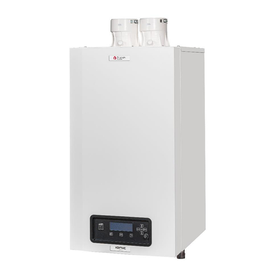
Summary of Contents for TriangleTube IONIC CB 299W
- Page 1 User Manual Low NOx certified to SCAQMD 1146.2 399W CB 299W- -470W-500W E95.1608.034 E95.1608.034 – E126100002...
-
Page 3: Table Of Contents
TABLE OF CONTENTS SAFETY GUIDELINES, ..........................5 INTRODUCTION ............................9 ........................... 9 XPLANATIONS ......................9 AINTENANCE AND INSPECTION On a Continuous basis ......................9 On a Monthly basis ......................10 On an Annual basis (every 12 months) ................10 Display and buttons ........................... - Page 4 IMPORTANT READ ALL OF THE FOLLOWING WARNINGS AND STATEMENTS BEFORE READING THE INSTALLATION INSTRUCTIONS DANGER Danger Sign: indicates the presence of an imminently hazardous situation that will cause death, serious personal injury or substantial property damage. WARNING Warning Sign: indicates the presence of a hazardous situation which can cause death, se- rious personal injury or substantial property damage.
-
Page 5: Safety Guidelines
1 SAFETY GUIDELINES, Use only your hand to turn the manual gas shutoff valve. Never use tools. If the manual valve will not turn by hand, don’t try to repair it, call a qualified service technician. Force or at- tempted repair may result in a fire or explosion STOP! Read the safety information above on Wait five (5) minutes to clear out any gas. - Page 6 CONSIGNES DE SÉCURITÉ N’utilisez que votre main pour tourner la vanne d’arrêt manuelle. N’utilisez jamais d’outils. Si la vanne manuelle ne tourne pas à la main, n’essayez pas de la réparer, appelez un technicien sevice qualifié. La force ou la tentative de réparation peut entraîner un incendie ou une explosion.
- Page 7 This boiler is equipped with a pressure switch. In the event of a blocked vent the boiler will lockout. No attempt by the user/owner should be made to put the boiler back intro operation. A qualified service technician must be notified of the issue. The boiler shall only be reset by a qualified service technician after they have diagnosed and corrected CAUTION the issued that caused the safety lockout of the boiler.
- Page 8 To meet commercial hot water requirements, the tank setpoint is adjustable up to 185°F. However, water temperatures over 125°F can cause severe burns instantly or death from scalds. This is the preferred starting point for setting the control for supplying general purpose hot water. WARNING: Water temperatures over 125 °F (52 °C) can cause severe burns instantly or death from scalding.
-
Page 9: Introduction
2 INTRODUCTION Ce manuel est écrit pour l’utilisateur. This manual is written for the user. Triangle Tube is not accountable for any damage Triangle Tube n'est pas responsable de tout dom- caused by failure to correctly follow these instruc- mage causé par ne pas suivre correctement de ces tions. -
Page 10: On A Monthly Basis
ONTHLY BASIS • Visually inspect the venting system for proper size and horizontal pitch and determine there is no blockage or restriction, leakage, corrosion and other deficiencies which could cause an unsafe condition. • Inspect around the exhaust vent and air inlet terminations outside the home for obstructions. Keep area clear of snow and debris. -
Page 11: Display And Buttons
3 Display and buttons 99.0 °F 170.0 °F 3.1 Explanation of the buttons On / off switch. Switches electrical power to the boiler Connector for computer cable Reset lockout error Main Menu Escape / Return to the status overview Right Enter a menu item or confirm selection in Status overview (when directly setting Actual setpoint or DHW setpoint) Left... -
Page 12: Display Configuration
3.2 Display configuration. The Status overview has three different sections that show specific information: Header Middle section 59 °F Footer Actual Setpoint 155 °F Header Left: For cascade systems the cascade icon is shown, with the cascade manager indication (M) or the dependent number. -
Page 13: Starting The Boiler
4 Starting the boiler. If the boiler is not on make sure the gas valve beneath the boiler is open and the power to the boiler has been connected and is turned on, use the on/off button to switch the boiler on. The following screen will occur: Initializing This screen is active during power up until communication with the main Control has been established. -
Page 14: Changing The Setpoint And/Or Enabling Ch/Dhw
4.1 Changing the Setpoint and/or Enabling CH/DHW. This can be done directly via the Status overview (as shown above) or via the MENU. When CH is active, you can adjust the Actual setpoint directly on the bottom of the Status overview. When DHW is active, you can adjust the DHW setpoint directly on the bottom of the Status overview. -
Page 15: Changing The Setpoint By The Menu (Button)
4.2 Changing the setpoint by the menu (Button). Enter the menu by pressing the MENU button once. The header in the display shows you are inside the main menu. While scrolling through the menu you will see that the selected menu item is shown in a white rectangle. Menu Central Heating (CH) Domestic Hot Water (DHW) -
Page 16: Other Menu Items
5 Other menu items 5.1 Protected menu items The display supports 3 different access levels; each with its own set of available menu items/parameters: Level Description 0: User Basic info and settings only that are accessible for everyone. 1: Installer Advanced information and settings;... -
Page 17: Change The Language Via The Menu Icons
HANGE THE LANGUAGE VIA THE MENU ICONS The next steps describe how to change the display language via the icons displayed inside the menu, which can be useful if a foreign language is set, causing the user not able to understand the menu. 1. -
Page 18: Available Menu Items
5.3 Available Menu items Depending on the installed/programmed options by the installer following menu items could be visible. Menu / Parameter Description Value / Unit Central Heating (CH) Enter the Central Heating (CH) menu Domestic Hot Water (DHW) Enter the Domestic Hot Water (DHW) menu Information Enter the Information menu Settings... -
Page 19: Boiler History
OILER ISTORY Menu / Parameter Description Value / Unit Successful Ignitions Display the number of successful ignitions Failed Ignitions Display the number of failed ignitions Flame Failures Display the number of flame losses Operation Days Display the total time in operation days CH Burner Hours Display the amount of burn hours for CH... -
Page 20: Time Zone Settings
IME ZONE SETTINGS Menu / Parameter Description Value / Unit Time Zone Correction Set the Time Zone Correction Daylight Savings Time Select the daylight savings time mode ISPLAY SETTINGS Menu / Parameter Description Value / Unit Time Notation Select 24h or 12h time notation 24h/12h Date Order Select the date-format... -
Page 21: Error Logging
5.4 Error logging Errors will be logged for a stand-alone system or for a complete cascade system (based on the cascade settings). The display will monitor the error number(s) it receives from the boiler(s): new errors will be stored in the error log. - Page 24 Your distributor: Triangle Tube 1240 Forest Parkway, Suite 100 West Deptford, NJ 08066 T: (856) 228 8881 F: (856) 228 3584 E: info@triangletube.com E126100002...
Need help?
Do you have a question about the IONIC CB 299W and is the answer not in the manual?
Questions and answers