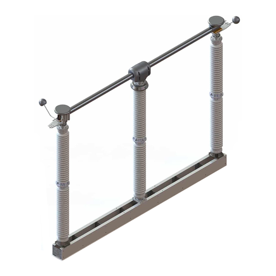
Southern States RDA-1 Installation Reference Manual
Double end break disconnect switch
Hide thumbs
Also See for RDA-1:
- Installation instructions manual (30 pages) ,
- Installation instructions manual (34 pages)
Advertisement
Quick Links
RDA-1 DOUBLE END BREAK DISCONNECT SWITCH
INSTALLATION REFERENCE GUIDE
This guide is intended to be used as a recommended sequence of work steps but does not
supersede the instruction manual (IB-111-RDA RDA-1) or assembly drawings. For assistance,
contact the Southern States Service Division (available 24/7) at 770-946-4565.
Scan for full instruction manual
Publication No. QSG111-RDA-1 R4 09142023
3
MOUNT PHASES PER ENGINEERING DRAWINGS
Refer to operating mechanism drawing for pole orientation and mounting
WARNING
Special Handling Required -
A qualified rigger and lift plan are
required due to possible off center,
high, center of gravity. Lift by switch
base only.
SLING ATTACHMENT
Refer To Instruction Book Section: Installation & Adjustment Procedures
6
INSTALL ADJUSTABLE ARM & DRIVE
PHASE CLEVIS
Drive Phase Clevis
Vertical Pipe
Refer To Instruction Book Section: Installation & Adjustment Procedures
1
REVIEW BILL OF LADING (BOL)
A.
Check the materials received against the packing list
B.
Report any shortages or damaged equipment to Southern States
C.
A typical shipment will include:
- 3 phase switch (base, insulators, & live parts)
- Operating mechanism box
- Operating pipe
Note: All material is marked with JO number
SECURE
BLADE WITH
TIES DURING
LIFTING
Typical Mounting
Bolt Locations
CONNECT & TIGHTEN DRIVE PIPE BETWEEN
7
ADJUSTABLE ARM & AUXILIARY ARM OF DRIVE
PHASE WITH APPROPRIATE CLEVISES
Step 7.1
Set switch to closed position
Adjustable Arm
Step 7.2
Set adjustable arm radius to
recommended length and set to
closed position
MOUNT VERTICAL BEARING,
4
PIPE, & OPERATOR
Mounting Bolt
Locations
Vertical Bearing
Support
Vertical Pipe
Refer To Instruction Book Section: Installation & Adjustment Procedures
NOTE:
DO NOT PIERCE UNTIL STEP 13
Step 7.3
Set 12" DIM. and
tighten Clevis
Step 7.4
Pierce pipe
Refer To Instruction Book Section: Installation & Adjustment Procedures
2
REVIEW BILL OF MATERIAL (BOM)
A.
Inventory all parts against the BOM found on the op-mech sheet inside
the drawing package
B.
Report any missing or damaged parts to Southern States
E
A
C
D
F
K
G
J
I
H
L
PIERCE VERTICAL BEARING
5
SET-SCREW COMPLETELY
Vertical
Bearing
Support
1/4" to
NOTE: Ensure the full weight of the
3/8" gap
vertical pipe is supported by the vertical
bearing and maintain the gap required
between the coupling and gear operator.
Then pierce collar. Also, confirm auxiliary
arm assembly is correctly mounted per the
operating mechanism drawing.
Vertical Bearing Set
Screw (Pierce Bolt)
Refer To Instruction Book Section: Installation & Adjustment Procedures
8
Drive Pipe
Note: Veritcal Pipe removed for clarity
Refer To Instruction Book Section: Installation & Adjustment Procedures
TERMINOLOGY OVERVIEW
A: Live Parts
B: Switch Jaw[s]
B
C: Switch Blade
D: Hinge Mechanism
E: Arcing Horns
F: Rotating Insulator
G: Mounting Adapter[s]
H: Jack Screw[s]
I: Switch Arm
J: Bearing Stop[s]
K: Auxiliary Arm Mounting
L: Switch Base
Advertisement

Subscribe to Our Youtube Channel
Related Manuals for Southern States RDA-1


Summary of Contents for Southern States RDA-1
- Page 1 C: Switch Blade This guide is intended to be used as a recommended sequence of work steps but does not D: Hinge Mechanism supersede the instruction manual (IB-111-RDA RDA-1) or assembly drawings. For assistance, E: Arcing Horns F: Rotating Insulator contact the Southern States Service Division (available 24/7) at 770-946-4565.
- Page 2 TEST-OPERATE THE DRIVE PHASE TO VERIFY ALL CRITERIA BELOW ARE MET. NOTES: • THERE MAY BE VARIATIONS ON CONTACT PLACEMENT AT DIFFERENT AMPERAGE CLASSES. • FOR ARCING HORN ADJUSTMENTS, REFER TO INSTRUCTION MANUAL. BLADE STOP BLADE STOP Contact fingers must be centered on The blade tips should enter the jaw centrally, Drive pipe on op-mech should be toggled This switch blade should hit both stops simultaneously and...
Need help?
Do you have a question about the RDA-1 and is the answer not in the manual?
Questions and answers