
Subscribe to Our Youtube Channel
Related Manuals for Southern States EC-2


Summary of Contents for Southern States EC-2
- Page 1 TYPE EC-2 Aluminum Center Side Break Disconnect Switch For 38 – 362 kV Ratings INSTALLATION & INSTRUCTION MANUAL...
- Page 2 Page II The Quality Name in High Voltage Switching...
- Page 3 Portions of it may not be applicable or may not have complete instructions for your specific equipment. If you do not understand any part of these instructions or need assistance, contact Southern States Service Division at 770-946-4562 during normal business hours (8:00am – 4:30pm EST, M-F) or 770-...
- Page 4 The Quality Name in High Voltage Switching LIMITED WARRANTY Southern States, LLC (“SSLLC”) warrants only to the Warranty Holder (hereinafter defined as the “End User” or the “Immediate Purchaser”, as applicable, pursuant to the terms and conditions of this Limited Warranty as set forth below), that the Product identified below will, upon shipment, be free of defects in workmanship and material for the applicable Warranty Period.
- Page 5 Page V The Quality Name in High Voltage Switching Southern States, LLC Equipment Receipt, Installation, Use, Operation and Maintenance Terms (“Terms of Use”)
- Page 6 Page VI The Quality Name in High Voltage Switching...
- Page 7 Page VII The Quality Name in High Voltage Switching Type EC-2...
-
Page 8: Table Of Contents
Page VIII The Quality Name in High Voltage Switching Table of Contents Chapter Page Table of Contents ........................VIII List of Tables and Figures ......................IX Summary & Introduction ......................1 Summary ..........................1 Important ..........................1 Introduction ..........................2 Introduction .......................... -
Page 9: List Of Tables And Figures
Table 4: Recommended Installation and Maintenance Table ............. 24 Figures Page Figure 1: Typical EC-2 Switch Pole Assembled & Common Terminology ........4 Figure 2: Match-Marked Components (Heavy Duty bearing) ............7 Figure 3: Match-Marked Components (Extra Heavy Duty bearing) ..........8 Figure 4: Insulator Stack Alignment (Heavy Duty Bearing) ............ -
Page 10: Summary & Introduction
The sales contract contains the entire obligations of Southern States. The Warranty contained in the contract between the parties is the sole warranty of Southern States. Any statements contained herein do not create new warranties or modify the existing warranty. -
Page 11: Introduction
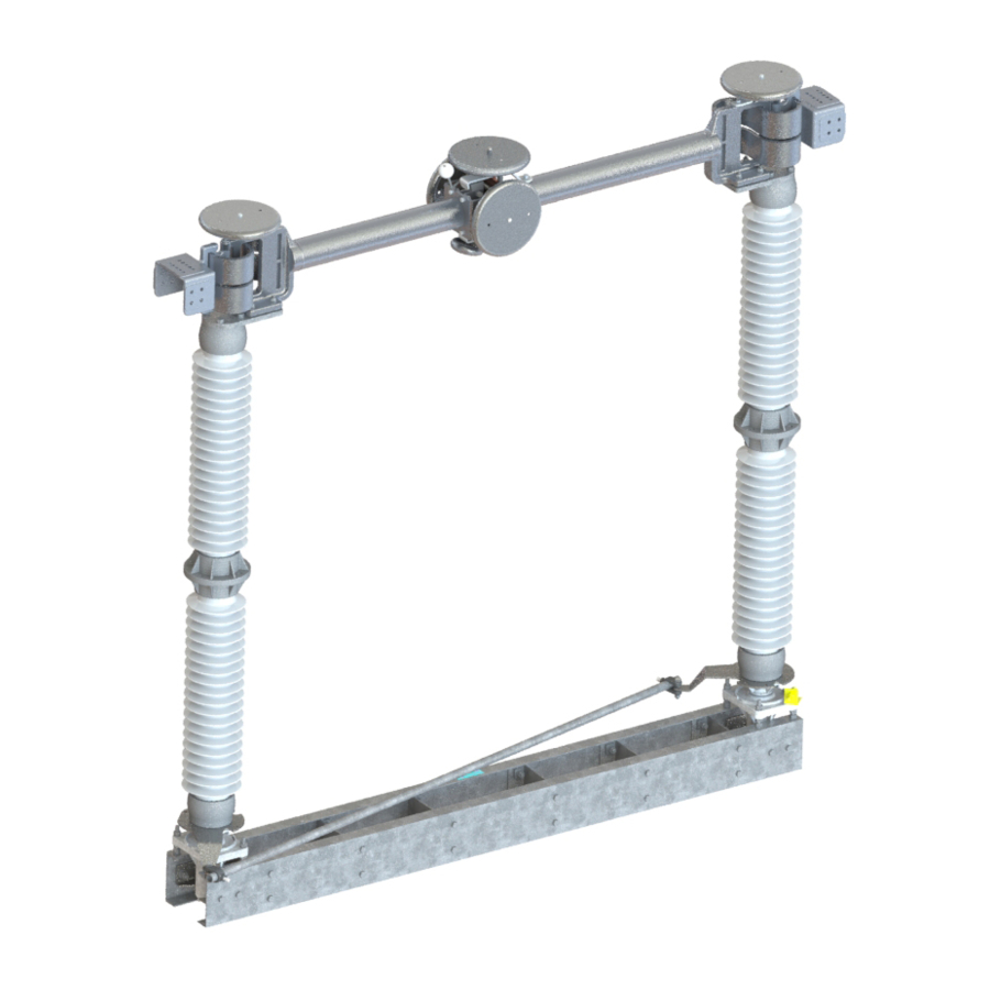
Page 2 of 25 Summary & Introduction Introduction Southern States Type EC-2 is a three phase, group operated, center side break air disconnect switch constructed primarily of high strength aluminum. Applications for these switches included disconnecting and sectionalizing of lines, and isolating or bypassing other electrical equipment. Poles can be mounted in a horizontal “upright,”... -
Page 12: Ratings
Page 3 of 25 Summary & Introduction Ratings Table 1: Ratings Table RATINGS Maximum Voltage Rating (kV) 48.3 72.5 BIL (kV) 900/1050 1050/1300 ADDITIONAL RATINGS Rated Power Frequency 60 Hz Continuous Current 3000 A 4000 A Short-Time Symmetrical 63 kA RMS 63 kA RMS Withstand (3 Sec.) 75 kA RMS... -
Page 13: Product Description
I – Male Blade Assembly N – Locking Mechanism E – Jacking Bolts J – Contact Fingers O – Contact Bar Figure 1: Typical EC-2 Switch Pole Assembled & Common Terminology (Corona Rings are for 245kV and above and are not shown.) -
Page 14: Receiving, Handling & Storage
If damage or a shortage is noted, file a claim immediately with the carrier and contact the factory. Storage All components of the EC-2 aluminum center side break disconnect switch are suitable for outdoor use and do not have any special storage requirements. Keep bearings out of standing water. Keep upright and support live parts with base. -
Page 15: Installation & Adjustment Procedures
Contact your local representative or the factory if questions should arise. Southern States Service Department is available for field installation assistance along with providing parts support for all Southern States products. -
Page 16: Preferred Switch Assembly Method
Page 7 of 25 Installation & Adjustment Procedures Preferred Switch Assembly Method 1. If Disconnect switch is shipped assembled on insulators Skip this section and continue to next section Mounting disconnect switch onto the structure. 2. Assemble the switch pole on the ground and hoist it to the structure as a complete unit. CAUTION: To prevent overturning during assembly, the switch base must be securely attached to a level, stable platform. - Page 17 Page 8 of 25 Installation & Adjustment Procedures Figure 3: Match-Marked Components (Extra Heavy Duty bearing) A = Inter-pole Arm B = Bearing Hub C = Bearing 7. Rotate the insulator to the closed position stop on the bearing. 8. Use a plumb bob or other straight line tool (e.g. laser level) to verify that the insulator is level. 9.
- Page 18 Page 9 of 25 Installation & Adjustment Procedures Figure 4: Insulator Stack Alignment (Heavy Duty Bearing) Figure 5: Insulator Stack Alignment (Extra Heavy Duty Bearing) (A = Jacking Bolt, B = Jacking Nut, C = Adjustment Bolt)
- Page 19 Page 10 of 25 Installation & Adjustment Procedures 10. When installing insulators on high capacity bearings, the insulators require special attention to ensure good switch operation. It is necessary that the insulators rotate about their axis uniformly; that is, they do not WOBBLE as they rotate. This is important due to irregularities in insulators.
- Page 20 Page 11 of 25 Installation & Adjustment Procedures Figure 6: Insulator Adjustment (1) Insulator rotates away If insulator wobbles, leave it at the same position in previous step. Use the • jacking screws, and tilt the insulator one-half the distance toward the reference point.
-
Page 21: Live Part Installation & Contact Adjustment
Page 12 of 25 Installation & Adjustment Procedures Live Part Installation & Contact Adjustment 1. Rotate bearing slightly to open, mount the male and female blade assemblies on top of the insulators using the hardware indicated on the Unit Assembly drawing (see Table 2). 1.1. - Page 22 Page 13 of 25 Installation & Adjustment Procedures 5. The male blade assembly should touch the blade stops as shown in Figure 8. If adjustment is necessary to achieve contact, loosen the bolts that attach the blades to the insulators, and use the bolt hole tolerances to adjust the spacing.
- Page 23 Page 14 of 25 Installation & Adjustment Procedures Figure 12: Blade Stops ( Extra Heavy Duty Bearing) A= Stop, B=Crank Arm stop, C= Adjusting bolt Figure 13: Hinge Assembly of 3000/4000A...
-
Page 24: Mounting Disconnect Switch Onto The Structure
Page 15 of 25 Installation & Adjustment Procedures Mounting disconnect switch onto the structure 1. Recheck the Operating Mechanism drawing to confirm the correct position of the disconnect switch pole on the structure. 2. With the switch closed, secure the male and female blade assemblies using rope or other type of strap, to avoid movement during lifting. - Page 25 Page 16 of 25 Installation & Adjustment Procedures Figure 16: Sling Attachment...
-
Page 26: Optional Accessories
Page 17 of 25 Installation & Adjustment Procedures Optional Accessories 1. Blade Lock (if equipped): In the closed position the blade lock hook should engage the locking post without touching it. There should be a 9/16” clearance between the locking hook and locking post. Refer to Figure 17. -
Page 27: Operating Mechanism
Page 18 of 25 Installation & Adjustment Procedures Operating Mechanism (See Operating mechanism drawings provided for details) 1. Lay out all Operating Mechanism parts and check them against the Op-Mech drawing bill-of- materials. 2. To ensure that the bearing stops do not interfere with switch adjustments, loosen all open/close bearing stops, and slide them out of the way. -
Page 28: Final Switch Adjustments (Tuning)
Page 19 of 25 Installation & Adjustment Procedures Final Switch Adjustments (Tuning) 1. The operating mechanism is intended to fully open and fully close the disconnect switch by rotating the vertical operating pipe about 180 using an operator (manual or electrical). The interphase pipe controls the individual operation of each switch pole, using a push/pull control. - Page 29 Page 20 of 25 Be aware that there is an adjustable stop on the operator. Do not over operate as damage will occur to the operator. Figure 20: Type SEGO (Safety Enhanced Gear Operator) 2.3. Swing handle operator 2.3.1. When the switch is properly adjusted the handle should hang vertically and free in both the open and closed positions to permit the use of a customer supplied padlock.
- Page 30 Page 21 of 25 3. Preliminary Switch Settings: 3.1. tart with the disconnect switch and operating mechanism in the closed position. Refer to Figure 21. 3.1.1. The switch is in the fully closed position when the centerline of the male blade assembly is aligned with the centerline of the Female Blade Assembly.
- Page 31 Page 22 of 25 Figure 22: Switch – Fully Open Position (Top View) Recommended Minimum Distance Switch Rating (kV) between any metal parts (inches) 72.5 245 (900 BIL) 245 / 362 (1050 BIL) 362 (1300 BIL) Table 3: Minimum Opening 4.7.
- Page 32 Page 23 of 25 4.8. Final Check: 4.8.1. Once all final adjustments are complete, be sure that all nuts are tightened to their specified torque (Refer to Table 2). 4.8.2. Apply a minimal amount of grease to the point of each piercing bolt and then tighten the bolt until it pierces the pipe wall.
-
Page 33: Recommended Inspection Maintenance
Recommended Inspection Maintenance Recommended Inspection Maintenance Southern States’ disconnect switches are designed to operate with minimum maintenance. While disconnecting switches are not readily serviced at frequent intervals, periodic inspection is important for satisfactory operation and maximized overall life. Frequency of inspection and maintenance depends on the installation site, weather, atmospheric conditions, experience of operating personnel, and any special operation requirements. -
Page 34: Patrolling Inspection (6 Months)
Page 25 of 25 Recommended Inspection Maintenance Patrolling Inspection (6 Months) The patrolling inspection is a largely visual inspection on an energized unit in service. The frequency of the inspection is determined by the local conditions and policies of the owner of the equipment. Inspect the insulators for breaks, cracks, burns, or cement deterioration. - Page 36 30 Georgia Avenue Hampton, Georgia 30228 Phone: 770-946-4562 Fax: 770-946-8106 E-mail: support@southernstatesllc.com http://www.southernstatesllc.com ©2021 Southern States, LLC IB-136-EC-2 362-R5 05042021 Printed U.S.A.
Need help?
Do you have a question about the EC-2 and is the answer not in the manual?
Questions and answers