
Subscribe to Our Youtube Channel
Related Manuals for Southern States ES-1


Summary of Contents for Southern States ES-1
- Page 1 Type ES-1 2 & 3 Way Aluminum Side Break Phase-Over-Phase Disconnect Switch For All Ratings INSTALLATION & INSTRUCTION MANUAL...
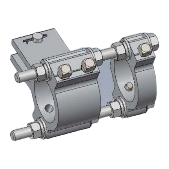
- Page 2 ATTENTION: Southern States will begin supplying a portion of new operating mechanism designs with Rapid-Set clevises for orders designed after 9/1/23. If your Operating Mechanism print calls for Rapid-Set clevises (see image below for an example), please utilize the instructions on the following pages for all linkage adjustments.
- Page 3 Please scan or use the link below for video instructions of Rapid-Set. Southern States Rapid Set Instructions S T E P 1 : Install the auxiliary arm by aligning the straight edge of the arm with the center of the vertical pipe and bolting it into place using two of the provided mounting holes.
- Page 4 S T E P 2 : Install the adjustable arm with the radius “R” set to the recommended length provided in the operating mechanism drawings. S T E P 3 : Install the auxiliary arm Rapid-Set clevis and drive pipe. Ensure that roughly 12” of pipe extends beyond the adjustable arm clevis connection so that the pipe makes contact with the adjustable arm in the position shown.
- Page 5 S T E P 4 : With the auxiliary arm properly aligned with the vertical pipe and the switch phase in the full closed position, pierce the pipe at both ends. NOTE: U-bolt style clevises require pre-drilling on all pipes thicker than SCH40.
- Page 6 S T E P 6 : After the drive phase is adjusted to operate correctly, set all phases to full closed, and install the interphase pipe following the procedure below. For switches driven by the center phase: a. With the interphase pipe centered and all clevises in place, pierce the interphase pipe at the locations shown.
- Page 7 For switches driven by one of the end phases: a. With the interphase pipe centered and all clevises in place, pierce the interphase pipe with at the locations shown. Do not remove plastic caps at this time. b. Adjust the timing of the center phase by adjusting the length “L” of the Rapid-Set clevis attached to the drive phase.
- Page 8 c. Set the timing of the last phase by adjusting the length “L” of the Rapid-Set clevis attached to the last phase. S T E P 7 : With all the phases adjusted, open and close the three phase assembly and inspect for proper operation. Once adjustments are finalized, pierce all remaining connections (switch operator, adjustable arm, etc).
- Page 9 The instructions in this manual are general guidelines for this type of equipment and not specific to the equipment supplied. Portions of it may not be applicable or may not have complete instructions for your specific equipment. If you do not understand any part of these instructions or need assistance, contact Southern States Service Division at 770-946-4562.
- Page 10 Page 1 of 34 The Quality Name in High Voltage Switching Type ES-1 2 Way Preliminary Release 11/11/2011...
- Page 11 Page 2 of 34 The Quality Name in High Voltage Switching Type ES-1 3 Way Preliminary Release 11/11/2011...
-
Page 12: Table Of Contents
Page 3 of 34 The Quality Name in High Voltage Switching Table of Contents Introduction ..........................6 Receiving ..........................6 Storage...........................6 General Information ......................6 Principles of Operation ......................7 Installation and Adjustment Procedures .................9 Typical Disconnect Switch ....................9 Preferred Switch Assembly Method ...................10 Unfold Switch ........................10 Mount Cross Braces to Switch Base ................14 Check Contact Adjustment ...................15... - Page 13 Page 4 of 34 The Quality Name in High Voltage Switching Figure 1: Typical Pole Mounted Switch with Operating Mechanism ........8 Figure 2: Common ES-1 2 & 3 Way Terminology..............9 Figure 3: Folded Switch ......................10 Figure 4: Unfolding First Base Member ..................11 Figure 5: Both Base Members Unfolded ................11...
- Page 14 The sales contract contains the entire obligation of Southern States. The warranty contained in the contract between the parties is the sole warranty of Southern States. Any statements contained herein do not create new warranties or modify the existing warranty.
-
Page 15: Introduction
The Quality Name in High Voltage Switching Introduction The Southern States Type ES-1 2 & 3 Way switches are three phase, group operated, side break air disconnect switches. The switches may be operated using a manual operator or an electric motor operator. The installation procedure for all mounting positions and operating schemes is similar and explained herein. -
Page 16: Principles Of Operation
(whether manual or electrical) to simultaneous rotation of the end insulator of each switch pole. Figure 1 shows a typical operating mechanism for a 2 Way ES-1 switch. In all cases the operating principle remains the same and the methods of installation and adjustment are virtually identical. - Page 17 Page 8 of 34 The Quality Name in High Voltage Switching Left-handed switch blade Right-handed switch blade Structure Clockwise Operating Mechanism Counterclockwise operating mechanism Figure 1: Typical Pole Mounted Switch with Operating Mechanism Preliminary Release 11/11/2011...
-
Page 18: Installation And Adjustment Procedures
Page 9 of 34 The Quality Name in High Voltage Switching Installation and Adjustment Procedures Typical Disconnect Switch In general, installing a Southern States Type ES-1 2 or 3 Way Disconnect Switch consists of the following: Unfolding the switch. -
Page 19: Preferred Switch Assembly Method
Safety precautions must be taken and safety guidelines carefully followed. Follow all NESC, OSHA, user, manufacturer, and local safety requirements. Steps shown apply equally to both 2 and 3 Way ES-1 switches. Unfold Switch 1) Remove any shipping braces or straps from the switch. Leave the shipping stands attached to the switch base to facilitate assembly. - Page 20 Page 11 of 34 The Quality Name in High Voltage Switching 2) Rotate switch base member 90°. See Figure 4. Figure 4: Unfolding First Base Member 3) Repeat with the other switch base member. See Figure 5. Figure 5: Both Base Members Unfolded Preliminary Release 11/11/2011...
- Page 21 Page 12 of 34 The Quality Name in High Voltage Switching 4) Insert hardware specified on the switch assembly drawing. Do not tighten hardware at this time. See Figure 6. Figure 6: Base Member Hardware 5) Close the switch blades. See Figure 7. Figure 7: Closed Switch Preliminary Release 11/11/2011...
- Page 22 Page 13 of 34 The Quality Name in High Voltage Switching 6) Extend the bearing stop bolt until it can interact with the bearing stops. See Figure 8. Stop Stop Bearing Stop Bolt Figure 8: Bearing Stop Bolt Height Preliminary Release 11/11/2011...
-
Page 23: Mount Cross Braces To Switch Base
Page 14 of 34 The Quality Name in High Voltage Switching Mount Cross Braces to Switch Base 1) Attach back member and cross braces specified in Operating Mechanism Drawing. See Figure 9. Cross Brace Cross Brace Back Member Cross Brace Figure 9: Base Frame Components Attached 2) Tighten the back member hardware, the cross brace hardware, and the switch base member hardware. -
Page 24: Check Contact Adjustment
Page 15 of 34 The Quality Name in High Voltage Switching Check Contact Adjustment All switches are factory adjusted and should require only fine tuning once attached to the structure. Still, it is a good idea to check the adjustment prior to mounting the switch. - Page 25 Page 16 of 34 The Quality Name in High Voltage Switching +1” + ½“ Figure 12: Blade Open Gap 5) If the blades are parallel and level and the gaps within the specified ranges, move on to the next section. 6) If the gaps are too large, use the insulator bearing jack bolts to tilt the male blade towards the jaw.
-
Page 26: Check Blade Stop Adjustment
Page 17 of 34 The Quality Name in High Voltage Switching Check Blade Stop Adjustment All switches are factory adjusted and should require only fine tuning once attached to the structure. Still, it is a good idea to check the adjustment prior to mounting the switch. - Page 27 Page 18 of 34 The Quality Name in High Voltage Switching 4) The closed position bearing stop, located at the bottom of the insulator, is correctly adjusted when there is a 1/16” to 1/8” clearance between the stop and the stop bolt. Adjust the stop if necessary. See Figure 15. Stop Bolt Stop Stop...
- Page 28 Page 19 of 34 The Quality Name in High Voltage Switching Copper Anti-Seize Catch Spring Figure 16: Left-Handed Blade Catch Position 8) If necessary, adjust the catch by loosening the bolt attaching the catch just enough to allow the catch to rotate. Move the catch to the proper position and hold it in position while the bolt is tightened.
- Page 29 Page 20 of 34 The Quality Name in High Voltage Switching 10) The typical blade opening, 90°, is shown in Figure 18 for a left-handed switch blade. Blade attachments may alter the opening angle. Refer to the Unit Assembly drawing for details. Figure 18: Left-Handed Minimum Open Angle 11) Conductor loads and switch attachments, such as interrupters, can alter fine switch adjustments, so final adjustments should be performed after connecting...
-
Page 30: Mount Switch Base To Structure
Page 21 of 34 The Quality Name in High Voltage Switching Mount Switch Base to Structure 1) Check the Operating Mechanism Drawing for proper mounting position. 2) With the switch closed, secure the blades using rope or other type of strap to avoid movement during lifting. -
Page 31: Mount Frame To Structure
Page 22 of 34 The Quality Name in High Voltage Switching Mount Frame to Structure 1) Check the Operating Mechanism Drawing for proper position of all frame members. See Figure 20. Diagonal Support Diagonal Support Lower Mounting Bracket Figure 20: Typical Frame Design 2) Mount the frame members using the hardware indicated by the Operating Mechanism Drawing. -
Page 32: Install Operating Mechanism Components
Do not pierce pipe at this time. 3. Refer to the Operating Mechanism drawing and install all mounting brackets, bearings, and bushings to the pole. See Figure 21 for a typical 2 Way ES-1 Operating Mechanism. - Page 33 Page 24 of 34 The Quality Name in High Voltage Switching 4. Tighten all hardware on the top bearing support. See Table 1 for recommended torque values. 5. Attach all required pipe clevises, adjustable arms, and other necessary components while mounting the first section of the vertical operating pipe. Refer to the Operating Mechanism Drawing for details.
- Page 34 Page 25 of 34 The Quality Name in High Voltage Switching Vertical Bearing Support Pipe Section 1 Vertical Bearing Support Pipe Connector Coupler Pipe Section 2 Vertical Bearing Support Figure 24: Typical Vertical Bearing Support Locations 8. Tighten hardware on any remaining pipe guides, bearings or bushings as the remaining sections of vertical pipe are hung.
-
Page 35: Adjust Switch And Operating Mechanism
Page 26 of 34 The Quality Name in High Voltage Switching Adjust Switch and Operating Mechanism 1) Switch Operating Devices: a) Worm gear operator (HOGO – High Output Geared Operator) The operator handle is factory set to rotate either clockwise or counter- clockwise to open the switch. - Page 36 Page 27 of 34 The Quality Name in High Voltage Switching c) Electrical motor operator Please refer to motor operator instruction manual for proper installation and setup. ii) Use manual operation while completing switch setup. iii) Do not electrically operate until all switch adjustments are complete. ALWAYS operate the motor operator decoupled first to ensure proper setup.
- Page 37 Page 28 of 34 The Quality Name in High Voltage Switching operating device’s coupling so that if slippage occurs during trial operations it can be detected. 3) Final Adjustment: a) Open the disconnect switch with the operator. b) If the switch is not fully open before the operator reaches the fully open position, the adjustable arm radius is too short.
- Page 38 Page 29 of 34 The Quality Name in High Voltage Switching v) Shorten the adjustable radius arm approximately ¼-inch. Allow the pipe clevis to reposition itself the same ¼ inch. Refer to Figure 27. vi) Operate and readjust as necessary. d) All phases of the fully adjusted disconnect switch should operate together although a slight variance between poles is acceptable.
-
Page 39: Optional Attachments
Service Department for field installation assistance and parts support if needed. Interrupters MAG-I, LLS-I, and LLS-II interrupters can be mounted to the 2 & 3 Way ES-1. Please refer to the Instruction Manuals for each interrupter for instructions on their installation, adjustment, and maintenance. -
Page 40: Recommended Inspection And Maintenance
Page 31 of 34 The Quality Name in High Voltage Switching Recommended Inspection and Maintenance The Southern States ES-12 & 3 Way Disconnect Switches have been designed to operate with low maintenance. Periodic inspection is important for satisfactory operation. Frequency of inspection and maintenance depends on the installation site, weather, atmospheric conditions, experience of operating personnel, and special ANSI Standard C37.35 is also a recommended guide for... -
Page 41: Routine Inspection And Maintenance (5 Year)
Page 32 of 34 The Quality Name in High Voltage Switching Important Safety precautions must be taken and safety guidelines carefully followed. Follow all NESC, OSHA, user, manufacturer, and local safety requirements. The switch must be disconnected from all power sources and adequate grounding put in place before Routine or Periodic Inspection and Maintenance of the switch. - Page 42 30 Georgia Avenue Hampton, Georgia 30228 Phone: 770-946-4562 Fax: 770-946-8106 E-mail: support@southernstatesllc.com http://www.southernstatesllc.com ©2012 Southern States, LLC IB-138-ES1-R0 02232012 Printed U.S.A.
Need help?
Do you have a question about the ES-1 and is the answer not in the manual?
Questions and answers