
Subscribe to Our Youtube Channel
Related Manuals for Southern States CSH


Summary of Contents for Southern States CSH
- Page 1 Appendix A-1 to RFP / Page 1 of 90 pages. Type CSH & CSH-B CSH2 & CSH2-B Circuit Switcher Horizontal Circuit Switcher 38kV to 245kV 1200, 1600, 2000 Amps INSTALLATION & INSTRUCTION MANUAL...
- Page 2 Appendix A-1 to RFP / Page 2 of 90 pages. Page I The Quality Name in High Voltage Switching...
- Page 3 Portions of it may not be applicable or may not have complete instructions for your specific equipment. If you do not understand any part of these instructions or need assistance, contact Southern States Service Division at 770-946-4562 during normal business hours (EST) or 770-946-4565 after normal business hours.
- Page 4 Appendix A-1 to RFP / Page 4 of 90 pages. Page II The Quality Name in High Voltage Switching Southern States, LLC Equipment Receipt, Installation, Use, Operation and Maintenance Terms (“Terms of Use”)
- Page 5 The Quality Name in High Voltage Switching LIMITED WARRANTY Southern States, LLC (“SSLLC”) warrants only to the Warranty Holder (hereinafter defined as the “End User” or the “Immediate Purchaser”, as applicable, pursuant to the terms and conditions of this Limited Warranty as set forth below), that the Product identified below will, upon shipment, be free of defects in workmanship and material for the applicable Warranty Period.
- Page 6 Appendix A-1 to RFP / Page 6 of 90 pages. Page IV The Quality Name in High Voltage Switching...
- Page 7 Appendix A-1 to RFP / Page 7 of 90 pages. Page V The Quality Name in High Voltage Switching Type CSH & CSH-B 38 kV – 245 kV...
-
Page 8: Table Of Contents
Receiving, Handling, & Storage ........................25 Receiving ..............................25 Handling & Unpacking ..........................26 Lifting a 1 Pole Arrangement ....................... 26 Lifting an Assembled CSH-B ....................... 27 Lifting the Motor Operator ........................28 Storage ..............................29 Short Term Storage (Less Than 3 Months) ..................29 Long Term Storage (More Than 3 Months) .................. -
Page 9: List Of Tables And Figures
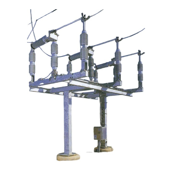
Figures Page Figure 1: CSH ............................... 3 Figure 2: CSH-B ............................3 Figure 3: CSH-B (Typical Construction) ......................4 Figure 4: Interrupter ............................5 Figure 5: Interrupter Operating Sequence ....................6 Figure 6: Operating Mechanism ........................7 Figure 7: Outboard Bearing........................... 8 Figure 8: Three Phase Linkage ........................ - Page 10 Appendix A-1 to RFP / Page 10 of 90 pages. Page VIII The Quality Name in High Voltage Switching Figure 47: Indicator in Green Band ......................41 Figure 48: Close-up of Indicator in Green Band ..................41 Figure 49: Shunt Trip View Port ......................... 42 Figure 50: Shunt Trip Gap..........................
-
Page 11: Summary & Information
This installation and instruction manual is written using the CSH-B as the focus. The guidelines provided should also be utilized when installing the CSH2-B. This manual can also be used as a guide for the CSH and CSH2 products which are similar but do not have the integral disconnect. -
Page 12: Introduction
Operation of the Southern States CSH-B is controlled by a motor operator or by a manual worm gear operator. The Southern States CSH-B is designed and certified to switch and protect transformers. The horizontal circuit switcher is also available without the integral disconnect (CSH). -
Page 13: Product Description
Overview The Type CSH is similar to the Type CSH-B. The CSH units do not have an integral disconnect blade. Line termination is on the driver end. Two, rather than three insulator columns are used to support and operate the interrupter. - Page 14 Product Description Complete CSH-B Group Outboard Control Bearing Pipe Charging Bolt Shunt Trip Interphase Lever Stop Bolt Pipe Assembly Interphase Brace Vertical Control De-Coupler Motor Operator Figure 3: CSH-B (Typical Construction) Note: Please refer to customer drawings for specific construction details.
-
Page 15: Interrupter
The interrupter is an SF puffer design. The contact structure is robust and designed for many switching operations. The CSH-B also utilizes a rupture disk that is designed to vent the gas in the event of an overpressure condition inside the interrupter. - Page 16 Appendix A-1 to RFP / Page 16 of 90 pages. Page 6 of 78 Product Description Interrupter trips with contacts “A” and “B” in the closed position. Contacts “A” and “B” remain in contact as “B” travels over “A” and compresses the gas. Gas is ready to flow when contact part. Contacts part –...
-
Page 17: Operating Mechanism
Product Description Operating Mechanism A typical three-pole arrangement of the CSH-B is shown in Figure 6: Operating Mechanism. The three single pole units are mechanically connected to operate simultaneously from a single operator, similar to group operation of a disconnect switch. - Page 18 Appendix A-1 to RFP / Page 18 of 90 pages. Page 8 of 78 Product Description Figure 7: Outboard Bearing...
-
Page 19: Three Phase Linkage
Appendix A-1 to RFP / Page 19 of 90 pages. Page 9 of 78 Product Description Three Phase Linkage Figure 8: Three Phase Linkage... -
Page 20: Driver
Appendix A-1 to RFP / Page 20 of 90 pages. Page 10 of 78 Product Description Driver The driver mechanism located at the top of the rotating insulator column contains the main closing springs, shunt trip charging bolt, trip latch, and lever system that controls interrupter opening and closing. The main operating shaft of the driver also operates the hinge mechanism of the disconnect switch. -
Page 21: Shunt Trip
Appendix A-1 to RFP / Page 21 of 90 pages. Page 11 of 78 Product Description Shunt Trip The shunt trip mechanism is a stored energy device with a trip coil that imparts high speed tripping to the interrupter. Energizing the trip coil releases a latch causing a spring to discharge, producing rapid rotation of the insulator (Figure 10: Shunt Trip). - Page 22 Appendix A-1 to RFP / Page 22 of 90 pages. Page 12 of 78 Product Description Figure 11: Shunt Trip Outer View...
-
Page 23: Motor Operator
The motor operator is shown in Figure 12: Motor Operator (Outer). The operator has high torque for use with a CSH-B and can be electrically operated from a remote station. Standard features include an all-aluminum enclosure with corrosion resistant fittings, swing out removable doors, local electrical and manual operation, position indicating lights, thermostatically controlled space heater, operations counter, provision for a security lock, a decoupler, and an internal auxiliary switch. - Page 24 Appendix A-1 to RFP / Page 24 of 90 pages. Page 14 of 78 Product Description Feature Location A. Indicating Lights B. Open & Close Pushbuttons C. Operations Counter D. Local-Remote Selector Switch E. Hand Crank Interlock Switch F. Motor, 48 VDC or 125 VDC G.
-
Page 25: Decoupler
With the handle in the up position, as shown, the locking pin is engaged in the output shaft slot. Because of the force imposed by the shunt trip charging springs when the CSH-B is in the open position, it is necessary to use the hand crank to decouple. - Page 26 Appendix A-1 to RFP / Page 26 of 90 pages. Page 16 of 78 Product Description Figure 15: Pull Pin Type Decoupler...
-
Page 27: Limit Switches
Appendix A-1 to RFP / Page 27 of 90 pages. Page 17 of 78 Product Description Limit Switches Limits of rotation are controlled by cam operated limit switches that are adjustable from 150 degrees to 200 degrees. The upper most cam and limit switch is always the open position limit switch and the lower cam and limit switch is always the close position limit switch. - Page 28 Appendix A-1 to RFP / Page 28 of 90 pages. Page 18 of 78 Product Description Figure 17: Limit Switches as seen from Side Door of Motor Operator...
-
Page 29: Position Indicators
There is a latch indicator on the underside of the housing of each driver. The painted marks serve to indicate limits of travel of the driver shaft and are used during installation and adjustment of the CSH-B operating linkage. They have no other function and should not be used for any other purpose. -
Page 30: Manual Operation
To open the CSH-B, operate the crank handle in the direction indicated on the sticker above the hand crank insertion point. Approximately three turns will open the interrupter. Crank from stop to stop on the outboard bearing lever in order to properly complete an opening or closing sequence. -
Page 31: Control Circuits
Page 21 of 78 Product Description Control Circuits Further detail can be found in the motor operator’s instruction book and in the customer drawings. This is a typical arrangement; consult customer drawings for the actual wiring of this particular CSH-B. - Page 32 Appendix A-1 to RFP / Page 32 of 90 pages. Page 22 of 78 Product Description Figure 20: Control Circuits (Typical)
-
Page 33: Typical Gas System
Appendix A-1 to RFP / Page 33 of 90 pages. Page 23 of 78 Product Description Typical Gas System Figure 21: Typical Gas System... -
Page 34: How To Read The Sf Density Gauge
How to Read the SF Density Gauge The Southern States CSH-B interrupter unit is equipped with a temperature compensated pressure gauge. The temperature compensated pressure gauge displays a constant pressure reading over the ambient temperature range of the switcher. Refer to Figure 22: Gauge Face. -
Page 35: Receiving, Handling, & Storage
Death by suffocation is possible. The Southern States CSH-B is packaged for shipment by the following two methods. Structure members (structural frame and support columns), when furnished by Southern States, are in a separate shipping group. -
Page 36: Handling & Unpacking
Appendix A-1 to RFP / Page 36 of 90 pages. Page 26 of 78 Receiving, Handling, & Storage Handling & Unpacking Lifting a 1 Pole Arrangement When lifting 1 pole at a time, remove the shipping braces, motor operator, pipe, and interphase brace assemblies. -
Page 37: Lifting An Assembled Csh-B
Page 27 of 78 Receiving, Handling, & Storage Lifting an Assembled CSH-B When lifting all 3 pole units at once, remove the motor operator, pipe, and interphase brace assemblies. Do not remove the shipping braces. Sling the pole units with 4 lifting straps as shown in Figure 25: Lifting 3 Pole Units. -
Page 38: Lifting The Motor Operator
Appendix A-1 to RFP / Page 38 of 90 pages. Page 28 of 78 Receiving, Handling, & Storage Lifting the Motor Operator The motor operator unit has two factory installed adjustable lock brackets on either side of the output shaft. Use appropriate cables or chains to lift into mounting position (Figure 26: Lifting Motor Operator). -
Page 39: Storage
Appendix A-1 to RFP / Page 39 of 90 pages. Page 29 of 78 Receiving, Handling, & Storage Storage After the receiving inspection, if immediate installation is not scheduled the equipment should be repacked and stored in a protected area. To maintain the "as new" condition the components, accessories, and spare parts should be stored indoors in a dry, clean place. -
Page 40: Installation & Adjustment Procedures
Lifting section to keep the assembly from falling over. The CSH-B, complete with insulators, is factory adjusted and timed on a 3-pole basis at the specified phase spacing and outboard bearing location. The unit has been operated at the factory via its motor operator by means of a temporary short section of vertical operating pipe. -
Page 41: Initial Assembly
Appendix A-1 to RFP / Page 41 of 90 pages. Page 31 of 78 Installation & Adjustment Procedures Initial Assembly 1. Mount the columns 1.1. Ensure orientation of columns are correct (refer to drawing) 1.2. Ensure columns are plumb 2. Mount platform to the top of the columns 2.1. - Page 42 Appendix A-1 to RFP / Page 42 of 90 pages. Page 32 of 78 Installation & Adjustment Procedures 5. Mount the Outboard Bearing Assembly 5.1. Orient the Outboard Bearing and bracket to allow rotation of the bearing as shown on drawing Figure 30: Mounting Outboard Bearing Orient Outboard...
- Page 43 Appendix A-1 to RFP / Page 43 of 90 pages. Page 33 of 78 Installation & Adjustment Procedures 6. Install the Vertical Control Pipe between the Outboard Bearing Clamp and the Motor Operator Clamp 6.1. Ensure the Vertical Control Pipe is against the stop of the Outboard Bearing Clamp This prevents the weight of the Vertical Control Pipe from resting on the Motor Operator •...
- Page 44 Appendix A-1 to RFP / Page 44 of 90 pages. Page 34 of 78 Installation & Adjustment Procedures 7. Mount Pole Assemblies 7.1. Lift one pole assembly at a time • Lift Pole Assembly using a 4-point lift, utilizing all four lifting lugs •...
- Page 45 • The braces establish the correct centerline distances between poles. If the braces do not fit when the poles are positioned correctly, contact Southern States. 7.6. Tighten the Interphase Brace hardware and torque per specification 7.7. Tighten pole assembly mounting hardware and torque per specification...
- Page 46 Appendix A-1 to RFP / Page 46 of 90 pages. Page 36 of 78 Installation & Adjustment Procedures 8. Install the Interphase Pipe Assembly 8.1. Match numbers on pipe assembly to the numbers marked on each pole assembly Figure 35: Installing Interphase Figure 36: Installing Interphase Pipe Assembly Pipe Assembly...
- Page 47 Appendix A-1 to RFP / Page 47 of 90 pages. Page 37 of 78 Installation & Adjustment Procedures 10. Tighten the U-bolts that connect the Motor Operator De-coupler to the Vertical Control Pipe - DO NOT PIERCE PIPE Figure 38: Tightening U-Bolts on Motor Operator De-coupler Tighten U-bolts DO NOT PIERCE PIPE WITH PIERCING BOLTS...
- Page 48 Figure 40: Dynamic Braking Resistor Dynamic Breaking Resistor 13. Manually operate the CSH/CSH-B to the full open position 13.1. Check the Over-toggle angle of the Outboard Bearing Lever Figure 41 13.1.1. Ensure the De-coupler handle is in the Up (coupled) position ( 13.1.2.
- Page 49 Appendix A-1 to RFP / Page 49 of 90 pages. Page 39 of 78 Installation & Adjustment Procedures 13.2. Verify that the Outboard Bearing Lever is over-toggled between 4 to 6 degrees 13.2.1. If the over-toggled angle of the Outboard Bearing Lever is not as specified, adjust the Outboard Bearing Stops to achieve the correct angle Figure 43: Over-toggle Angle of Figure 44: Adjusting...
- Page 50 Appendix A-1 to RFP / Page 50 of 90 pages. Page 40 of 78 Installation & Adjustment Procedures Figure 45: Aligning De-Coupler Figure 46: Shimming Motor with Lock Bracket Operator Shim as shown (if required) to De-Coupler Handle level Motor Operator (In De-Coupled position) Lock Bracket 15.
-
Page 51: Final Adjustments
Appendix A-1 to RFP / Page 51 of 90 pages. Page 41 of 78 Installation & Adjustment Procedures Final Adjustments: 17. Check/Adjust the Shunt Trip Gap, the rotational stroke of the Driver Mechanism, and the Disconnect Blade centering in the Stationary Contact Jaws 17.1. - Page 52 Appendix A-1 to RFP / Page 52 of 90 pages. Page 42 of 78 Installation & Adjustment Procedures Figure 49: Shunt Trip View Port Figure 50: Shunt Trip Gap Remove Cap to Check Shunt Trip Gap 1/8” to 3/16” Gap Shunt Trip View Port Shunt Trip Roller...
- Page 53 Appendix A-1 to RFP / Page 53 of 90 pages. Page 43 of 78 Installation & Adjustment Procedures 17.2. For any shunt trips that are not latched or do not meet the gap criteria above, perform the following steps: DO NOT THREAD THE CHARGING BOLT IN TOO FAR. There should be a minimum of 1 ¼”...
- Page 54 Appendix A-1 to RFP / Page 54 of 90 pages. Page 44 of 78 Installation & Adjustment Procedures 17.3. Note the location of the indicators in the green bands again (information to be used later) The location of the indicator will change if the shunt trip gap is adjusted •...
- Page 55 Appendix A-1 to RFP / Page 55 of 90 pages. Page 45 of 78 Installation & Adjustment Procedures 17.6. Verify that all three interrupters have closed when Motor Operator is in the full closed position. 17.7. Ensure the Lever Stop Bolt is not against the Switch Arm. Figure 54: Gap between Lever Stop Bolt and Switch Arm Switch Arm Lever Stop Bolt...
- Page 56 Appendix A-1 to RFP / Page 56 of 90 pages. Page 46 of 78 Installation & Adjustment Procedures 17.8. Check and note the location of the indicator with respect to the red band The indicator should have travelled ½ to ¾ of the distance into the red band (rotating •...
- Page 57 Appendix A-1 to RFP / Page 57 of 90 pages. Page 47 of 78 Installation & Adjustment Procedures 17.10. If the indicator was less than ½ into both the green and red band the stroke must be increased by increasing the length of the Outboard Bearing lever: 17.10.1.
- Page 58 Appendix A-1 to RFP / Page 58 of 90 pages. Page 48 of 78 Installation & Adjustment Procedures 17.10.12. If the indicator is located properly in the green band, manually crank the Motor Operator to the full closed position and check the location of the indicator in the red band.
- Page 59 Appendix A-1 to RFP / Page 59 of 90 pages. Page 49 of 78 Installation & Adjustment Procedures 17.11.11. If the indicator is not positioned in the green band as specified, go back to the beginning of step 17 17.11.12. If the indicator is located properly in the green band, manually crank the Motor Operator to the full closed position and check the location of the indicator in the red band.
- Page 60 Appendix A-1 to RFP / Page 60 of 90 pages. Page 50 of 78 Installation & Adjustment Procedures 17.12.11. If the indicator is not positioned in the green band as specified, go back to the beginning of step 17 17.12.12. If the indicator is located properly in the green band, manually crank the Motor Operator to the full closed position and check the location of the indicator in the red band.
- Page 61 Appendix A-1 to RFP / Page 61 of 90 pages. Page 51 of 78 Installation & Adjustment Procedures 17.13.10. After adjusting the shunt trip gap, re-check the position of the indicator in the green band. 17.13.11. If the indicator is not positioned in the green band as specified, go back to the beginning of step 17 17.13.12.
- Page 62 Appendix A-1 to RFP / Page 62 of 90 pages. Page 52 of 78 Installation & Adjustment Procedures 18.4. If either of the above are not correct, adjust the Disconnect Blade 18.4.1. Loosen the blade clamp bolts using a ¾” wrench/socket 18.4.2.
- Page 63 Appendix A-1 to RFP / Page 63 of 90 pages. Page 53 of 78 Installation & Adjustment Procedures 19. Check/Adjust the simultaneity of the interrupters (for closing operation) 19.1. Verify that the Lever Stop Assembly Bolt is touching the switch arm (or has very little gap) 19.1.1.
- Page 64 Appendix A-1 to RFP / Page 64 of 90 pages. Page 54 of 78 Installation & Adjustment Procedures 19.4. If the amount of rotation of the Manual Crank Handle between closing the first interrupter and the last interrupter is more than half a turn (180 degrees) the timing of the interrupters must be adjusted as follows: 19.4.1.
- Page 65 Appendix A-1 to RFP / Page 65 of 90 pages. Page 55 of 78 Installation & Adjustment Procedures 19.6. Re-verify the location of the indicator in the green band and the shunt trip gap 19.6.1. If adjustment is required, repeat step 17 as needed 20.
- Page 66 Appendix A-1 to RFP / Page 66 of 90 pages. Page 56 of 78 Installation & Adjustment Procedures 22. Check that the Disconnect Blade rests on the Blade Stop when in the full closed position and verify that there is proper down-force on the Disconnect Blade. Figure 68: Disconnect Blade Resting on Blade Stop Disconnect Blade is to be resting on...
- Page 67 Appendix A-1 to RFP / Page 67 of 90 pages. Page 57 of 78 Installation & Adjustment Procedures 22.4. If required, adjust the angle of the Disconnect Blade or downward pressure on the Disconnect Blade 22.4.1. Loosen the setscrew in the fork 22.4.2.
- Page 68 Appendix A-1 to RFP / Page 68 of 90 pages. Page 58 of 78 Installation & Adjustment Procedures 23. Check the vertical position of the Disconnect Blade such that it is at least 90 degrees from the 23.1. If not done, manually crank the Motor Operator to the full open position 23.2.
- Page 69 Appendix A-1 to RFP / Page 69 of 90 pages. Page 59 of 78 Installation & Adjustment Procedures Figure 72: Disconnect Hinge Assembly Crank Arm Adjusting Bolts (Beneath Rubber Cover) Crank Arm Figure 73: Crank Arm Adjusting Bolts Adjust angle of blade by threading one bolt in while threading the other out Tighten this nut to Tighten this nut to...
- Page 70 Appendix A-1 to RFP / Page 70 of 90 pages. Page 60 of 78 Installation & Adjustment Procedures 24. Adjust the open limit switch on the Motor Operator 24.1. If not done, manually crank the Motor Operator to the full open position 24.2.
-
Page 71: Post-Setup Checklist
Appendix A-1 to RFP / Page 71 of 90 pages. Page 61 of 78 Installation & Adjustment Procedures Post-Setup Checklist STRUCTURE Complete Initials Anchor Bolts have been torqued Platform mounting hardware has been torqued All Interphase Brace mounting hardware has been torqued All Pole Assemblies have been position to have the correct phase-to-phase distance All Pole Assembly mounting hardware has been torqued... - Page 72 Appendix A-1 to RFP / Page 72 of 90 pages. Page 62 of 78 Installation & Adjustment Procedures DISCONNECT Complete Initials Blade Clamp Bolts are tight Disconnect Blades are parallel to the Terminal Pads to within 5 degrees Disconnect Blades are centered between the Jaws Stationary Contact Shoes are centered on the Disconnect Blades lengthwise Disconnect Blades are resting on the Blade Stop...
-
Page 73: Sf 6 Fill Instructions
Installation & Adjustment Procedures Fill Instructions Typically, a fill kit is provided with the CSH-B. There is no need to pull vacuum unless the unit is no gas. Refer to Removal of SF6 Gas for more details on removing gas from the longer filled with pure SF CSH-B. -
Page 74: Gas Fill Pressures
VOLTAGE FAULT INT RATING RANGE PRESSURE @ 20 170 kV & Below All Ratings C TO +50 81 psig CSH & CSH-B 242 kV All Ratings C TO +40 86 psig 31.5 kA C TO +50 76 psig CSH2 & CSH2-B 145 kV &... -
Page 75: Measuring Contact Resistance
Appendix A-1 to RFP / Page 75 of 90 pages. Page 65 of 78 Installation & Adjustment Procedures Measuring Contact Resistance Interrupter Contact Resistance is measured from A to B. Blade Contact Resistance is measured from B to C. Overall Contact Resistance is measured from A to C. The maintenance and inspection tests call for the interrupter contact resistance. -
Page 76: Recommended Inspection And Maintenance
Appendix A-1 to RFP / Page 76 of 90 pages. Page 66 of 78 Recommended Inspection and Maintenance Recommended Inspection and Maintenance Post-Installation Checklist Substation Information: Substation Name: Date of Installation: Switcher Type Rating Mechanism Type Serial – J.O. Location: Address: City: State:... - Page 77 Appendix A-1 to RFP / Page 77 of 90 pages. Page 67 of 78 Recommended Inspection and Maintenance Cabinet Check: Item Done (√) Inspect Field Wiring Cabinet Wiring Secure Check that all Mechanical Connections are Secure Ensure that there are no additional parts on the floor of the cabinet Inspect Motor Operator for loose parts Is the Heater energized and/or does the...
- Page 78 Appendix A-1 to RFP / Page 78 of 90 pages. Page 68 of 78 Recommended Inspection and Maintenance Moisture Levels (Optional) (less than 500 ppm): Level _______________ ppm Record Final Operations Date: Counter: DDITIONAL COMMENTS NSPECTION ATE OF ITNESS NSPECTION IGNATURE...
-
Page 79: Maintenance Schedule
Recommended Inspection and Maintenance Maintenance Schedule The CSH-B has been designed to operate with low maintenance. Periodic inspection is important for satisfactory operation. Frequency of inspection and maintenance depends on the installation site, weather and atmospheric conditions, experience of operating personnel, and special operational requirements. -
Page 80: Periodic Inspection Checklist
Appendix A-1 to RFP / Page 80 of 90 pages. Page 70 of 78 Recommended Inspection and Maintenance Periodic Inspection Checklist Periodic Inspection ChecklistStation Date of Inspection: Circuit Switcher Type Rating Mechanism Type Serial – J.O. Instruction Books Control Diagram Control Voltage Heater Voltage Monthly Inspection... -
Page 81: 3-Year Inspection Checklist
Appendix A-1 to RFP / Page 81 of 90 pages. Page 71 of 78 Recommended Inspection and Maintenance 3-Year Inspection Checklist Station Date of Inspection: Circuit Switcher Type Rating Mechanism Type Serial – J.O. Instruction Books Control Diagram Control Voltage Heater Voltage Prior to performing inspection of the circuit switcher, ensure that there is rated in the pole units before testing the unit. -
Page 82: 6-Year Inspection Checklist
Appendix A-1 to RFP / Page 82 of 90 pages. Page 72 of 78 Recommended Inspection and Maintenance 6-Year Inspection Checklist Station Date of Inspection: Circuit Switcher Type Rating Mechanism Type Serial – J.O. Instruction Books Control Diagram Control Voltage Heater Voltage Prior to performing inspection of the circuit switcher, ensure that there is rated in the pole units before testing the unit. - Page 83 Appendix A-1 to RFP / Page 83 of 90 pages. Page 73 of 78 Recommended Inspection and Maintenance Trip command - Opening Time (Rated Voltage) < OR = 100 ms @ 48 VDC < OR = 80 ms @ 125 VDC Simultaneity ≤...
-
Page 84: Appendix
Corrosive Effects of SF By-Products in its pure dry form is chemically very stable and causes no corrosion. When the by-products come into CSH-B contact with moisture, corrosive compounds can form. The has adsorbent in the gas volume to keep the gas dry;... -
Page 85: Appendix B. Handling Sf
Page 75 of 78 Appendix Appendix B. Handling SF NOTE: The CSH-B is shipped with 5 to 10 psig of dry SF Gas. If the CSH-B arrives with the proper pressure of SF gas, do not remove gas or vacuum evacuate. -
Page 86: Appendix C. Doble Power Factor Testing
Both of these test values are recorded on the test report that is supplied with the product. These methods have been used for years at Southern States with great success to qualify production units for installation in the field. -
Page 87: Appendix D. Troubleshooting Guide
Appendix A-1 to RFP / Page 87 of 90 pages. Page 77 of 78 Appendix Appendix D. Troubleshooting Guide Apparent Problem Possible Solutions An Outside Pole Does Not Close Insufficient shunt trip gap in the open position. Adjust for gap with the shunt trip charging bolt. Screwing in on the charging bolt to obtain more gap reduces rotation into the green band. -
Page 88: Appendix E. Trip-Free Operation/Testing
Appendix Appendix E. Trip-Free Operation/Testing The Southern States Type CSH(2) and CSH(2)-B horizontal circuit switchers are designed so that, if inadvertently closed into a fault, the switcher will immediately open and interrupt the fault. The opening springs and the shunt trips are charged at the end of the opening stroke. So, when a closing operation is commanded, the opening mechanism is already set to open the interrupters. - Page 89 Appendix A-1 to RFP / Page 89 of 90 pages.
- Page 90 Appendix A-1 to RFP / Page 90 of 90 pages. 30 Georgia Avenue Hampton, Georgia 30228 Phone: 770-946-4562 Fax: 770-946-8106 E-mail: support@southernstatesllc.com http://www.southernstatesllc.com ©2021 Southern States, LLC IB-803-CSH(2)/CSH(2)-B245-R9h 03/10/2021 Printed U.S.A.
Need help?
Do you have a question about the CSH and is the answer not in the manual?
Questions and answers