
Subscribe to Our Youtube Channel
Related Manuals for Southern States EV-2H


Summary of Contents for Southern States EV-2H
- Page 1 Type EV-2H Aluminum Vertical Break Disconnect Switch thru 245 kV INSTALLATION & INSTRUCTION MANUAL...
- Page 2 Page II The Quality Name in High Voltage Switching...
- Page 3 Page III The Quality Name in High Voltage Switching Safety Information...
- Page 4 The Quality Name in High Voltage Switching LIMITED WARRANTY Southern States, LLC (“SSLLC”) warrants only to the Warranty Holder (hereinafter defined as the “End User” or the “Immediate Purchaser”, as applicable, pursuant to the terms and conditions of this Limited Warranty as set forth below), that the Product identified below will, upon shipment, be free of defects in workmanship and material for the applicable Warranty Period.
- Page 5 Equipment. • The Purchaser will, within seven (7) days after receipt of the Equipment, inspect the Equipment and identify and notify Southern States in writing of any missing parts, damage or defects observed in the Equipment.
- Page 6 Southern States consent. • In the event that Southern States is found by a court of competent jurisdiction or a properly empaneled arbitral body to be liable to the Purchaser for any reason, Southern States shall be entitled to a reduction in the liability by taking into account the exceptions provided by statute, law, and any counterclaims Southern States may have against Purchaser.
- Page 7 Page VII The Quality Name in High Voltage Switching Type EV-2H Aluminum Vertical Break Disconnect Switch Thru 245 kV...
-
Page 8: Table Of Contents
Page VIII The Quality Name in High Voltage Switching Table of Contents Table of Contents ........................... VIII List of Tables and Figures ........................ IX Summary & Introduction ........................1 Summary ............................1 Important ............................1 Introduction ............................ 2 Recommended Tools & Values ...................... 3 Product Description ........................... -
Page 9: List Of Tables And Figures
Table 2: Recommended Installation and Maintenance Table ................19 Figures Page Figure 1: Typical EV-2H disconnect switch & Common Terminology ..............4 Figure 2: Match-Marked Components ........................6 Figure 3: Insulator Stack Alignment ........................7 Figure 4. Contact blade centered among contact fingers..................8 Figure 5. -
Page 10: Summary & Introduction
The sales contract contains the entire obligations of Southern States. The Warranty contained in the contract between the parties is the sole warranty of Southern States. Any statements contained herein do not create new warranties or modify the existing warranty. -
Page 11: Introduction
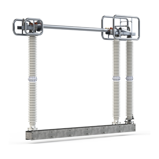
Summary & Introduction Introduction The Southern States type EV-2H is a three phase, group operated, vertical break air disconnect switch. Poles can be mounted in a horizontal “upright”, vertical, or under hung position. The switch may be operated using a manual operator or electrical motor operator. -
Page 12: Recommended Tools & Values
Page 3 of 21 Summary & Introduction Recommended Tools & Values Table 1: Recommended Tools and Torque Values Recommended Tools Recommended Torque Values Type Sizes Bolt/Nut size Torque (Ft-lb) Hand Wrenches and/or 15/16”, 3/4", 1/2” Sockets 5/8”, 9/16” Drill Bit 1/4”... -
Page 13: Product Description
J – Contact Bar P - Base E – Counter Balance K – Terminal Pad Q –Arcing Horn F – Blade Socket L – Switch Operating Arm R – Braided Connector Figure 1: Typical EV-2H disconnect switch & Common Terminology... -
Page 14: Receiving, Handling, & Storage
Storage All components of the EV-2H vertical break disconnect switch are suitable for outdoor use and do not have any special storage requirements. If a motor operator is furnished be sure to connect the heater circuit, using the provided external wiring, while the unit is in storage. -
Page 15: Installation & Adjustment Procedures
Page 6 of 21 Installation & Adjustment Procedures Installation & Adjustment Procedures Assembly 1. Preferred Switch Assembly Method 1.1. If Disconnect switch is shipped assembled on insulators Skip Section 1 and Continue to Section 2. 1.2. Switches rated 72.5 KV and above are normally shipped assembled separately from their insulators, with the live parts of each unit bolted to their own base. - Page 16 Page 7 of 21 Installation & Adjustment Procedures 1.6.1. Always be sure to tighten the bottom hex nuts securely after jackscrew adjustments are complete (Figure 3). 1.6.2. After making sure that the rotating insulator is perpendicular to the base, use the jackscrews on the rigid hinge insulator to line up the mounting holes (do not force the parts), and bolt the hinge assembly into position.
-
Page 17: Contact Adjustment
Page 8 of 21 Installation & Adjustment Procedures 2. Contact Adjustment 2.1. There are five conditions that determine proper contact adjustment. All conditions must be checked after conductor attachment to both ends of the switch pole 2.1.1. The jaw contact leaves (fingers) must be centered on the silver of the blade tip as shown in Figure 4. - Page 18 Page 9 of 21 Installation & Adjustment Procedures 2.1.3. The blade tip must come down into the jaw in its center, without dragging on either side as shown in Figure 6. Use the jack screws that support the jaw insulator to tilt the insulator sideways, if necessary to ensure this condition. Figure 6.
-
Page 19: Mounting Disconnect Switch Onto The Structure
Page 10 of 21 Installation & Adjustment Procedures 2.1.6. ENERGIZE THE SWITCH ONLY AFTER A FINAL INSPECTION OF ALL FIVE OF THESE CONDITIONS FOR PROPER CONTACT. 3. Optional Accessories 3.1. Arcing Horns (if equipped): 3.1.1. Refer to the Unit Assembly drawing for necessary hardware and installation location. - Page 20 4.6. The Mounting Positions and Proper Blade Openings are shown in Figure 10. Figure 10: Proper Mounting Positions 4.6.1. Conventional blade open positions are shown in Figure 10. The EV-2H switch will be shipped with one of these blade open angles unless another angle is specified.
- Page 21 Page 12 of 21 Installation & Adjustment Procedures 4.7. GENERAL INSTALLATION NOTE: Live part stops (the blade open and closed position stop bolts located on the parts above the insulators) are correctly engaged when touching lightly. The over travel bearing stops at the bottom of the insulator are correctly adjusted when there is a 1/16”...
-
Page 22: Operating Mechanism
In all cases, however, the operating principle remains the same, and the methods of installation and adjustment are virtually identical. Figure 13: Typical Operating Mechanism for EV-2H Figure 14: Alternate Operating Mechanism Designs... - Page 23 Page 14 of 21 Installation & Adjustment Procedures 5.3. Lay out all the operating mechanism parts and check them against the Operating Mechanism drawing bill-of-material. 5.4. To aid switch inspection from the ground, there will be at least one threader bolt (piercing bolt) on every Operating Mechanism.
-
Page 24: Switch Adjustments (Tuning)
Page 15 of 21 Installation & Adjustment Procedures 6. Switch Adjustments (Tuning) 6.1. The operating mechanism is intended to fully open and fully close the disconnect switch by rotating the vertical operating pipe 180 ± using an operator (manual or electrical). The interphase pipe controls the individual operation of each switch pole, using a push/pull control. - Page 25 Page 16 of 21 Installation & Adjustment Procedures 6.2.2. Worm gear operator (SEGO – Safety Enhanced Gear Operator) (Optional) 6.2.2.1. The weight of the vertical operating pipe should be supported by pipe collar by maintaining the ¼”-3/8” gap. 6.2.2.2. When the switch is properly adjusted the operator handle should hang freely in both the open and closed positions to permit the use of the customer supplied padlock.
- Page 26 Page 17 of 21 Installation & Adjustment Procedures 6.2.4.3. Do not electrically operate until all switch adjustments are complete. ALWAYS operate the motor operator decoupled first to ensure proper setup. 6.3. Preliminary Switch Settings: 6.3.1. Start with the disconnect switch and operating mechanism in the closed position. Refer to Figure 18 6.3.2.
- Page 27 Page 18 of 21 Installation & Adjustment Procedures Figure 19: Adjustable Arm Assembly 6.4.4. If the switch is fully open before the operator reaches the fully open position, the adjustable arm radius is too long. To correct: 6.4.4.1. Check to see that nothing has slipped. 6.4.4.2.
-
Page 28: Recommended Inspection Maintenance
Recommended Inspection Maintenance Recommended Inspection Maintenance Southern States’ disconnect switches are designed to operate with minimum maintenance. While disconnecting switches are not readily serviced at frequent intervals, periodic inspection is important for satisfactory operation and maximized overall life. Frequency of inspection and maintenance depends on the installation site, weather, atmospheric conditions, experience of operating personnel, and any special operation requirements. -
Page 29: Patrolling Inspection (6 Months)
Page 20 of 21 Recommended Inspection Maintenance Patrolling Inspection (6 Months) The patrolling inspection is a largely visual inspection on an energized unit in service. The frequency of the inspection is determined by the local conditions and policies of the owner of the equipment. •... - Page 30 30 Georgia Avenue Hampton, Georgia 30228 Phone: 770-946-4562 Fax: 770-946-8106 E-mail: support@southernstatesllc.com http://www.southernstatesllc.com ©2021 Southern States, LLC IB-101-EV2H 245-R6 02152021 Printed U.S.A.
Need help?
Do you have a question about the EV-2H and is the answer not in the manual?
Questions and answers