Advertisement
Quick Links
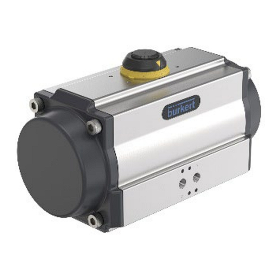
Type 2055
INSTRUCTIONS OF
ASSEMBLY AND MAINTENANCE
GENERAL
This instruction manual contains important information regarding
the installation, operation, maintenance and storage for rack and
pinion pneumatic actuators. Please read these instructions
carefully and save them for future reference. It is important that
only properly trained personnel to disassemble or assemble the
actuator.
DESCRIPTION OF TYPE 2055
The Aluminum pneumatic actuator is a 90° double acting or
spring return rack and pinion system, which has been designed
for the actuation of all type of 1/4 turn valves or 1/4 turn
applications.
The special finish of the interior surface of the body (Ra 0,4 -
0,6 µm) together with the use of antifriction pads manufactured
in material of a very low coefficient of friction (LAT LUB),
mounted in the pistons, prevent metal-metal contact. Bürkert
actuators enjoy a long and maintenance free life.
ATEX Technical Parameter
-Applicable Zone: 1, 2 zone; 21, 22 zone
-Maximum surface temperature: T6 (85°C)
-ATEX M a r k :
II2 G Ex h IIC T6 Gb
Operating Media
-Clean, dry or lubricated compressed air
-Light hydraulic oil
-Inert and non-corrosive gas (to consult)
The maximum particle size must not exceed 30μm.
Supply Pressure
Minimum:2 bar
Maximum:10 bar (150 psi)
Operating Temperature
Standard (NBR O-ring): –40°C...+80°C
High temperature (Viton O-ring): –20°C...+150°C
Low temperature (Silicon O-ring): –60°C...+80°C
Caution: For low and high temperature service, special grease is required.
High and low temperature will vary the output torque of the actuator.
LUBRICATION
The actuator is supplied ready-lubricated, no further lubrication is
required.
-Do not operate the actuator by using inflammable, oxidative
and corrosive, explosive or instable gases.
-Operating the actuator beyond its stated maximum operating limits
of pointed out temperature, pressure or recommend operating
media, can cause personal safety risks involving death or injury,
and or damage internal components as well as cause damage to
actuator housing.
PRINCIPLE OF OPERATION
■
Double acting actuator
Standard rotation
2
4
2
4
2
90° open
0° close
90° open
Standard rotation:
Air to port 2 forces the pistons outwards, causing the drive shaft to tum counterclockwise
while the air is being exhausted from pot 4.
Air to port 4 forces the pistons inwards, causing the drive shaft to turn clockwise while
the air is being exhausted from port 2.
Reverse rotation:
Air to port 2 forces the pistons outwards, causing the drive shaft to turn clockwise while
the air is being exhausted from port 4.
Air to port 4 forces the pistons inwards, causing the drive shaft to turn counterclockwise
while the air is being exhausted from port 2.
Spring return actuator
■
Standard rotation
2
4
2
4
2
90° open
90° open
0° close
Standard rotation:
Air to port 2 forces the pistons outwards, causing the springs to compress, the drive
shaft turns counterclockwise while air is being exhausted from port 4.
Loss of air pressure on port 4, the stored energy in the springs forces the pistons
inwards. The drive shaft turns clockwise while air is being exhausted from port 2.
Reverse rotation:
Air to port 2 forces the pistons outwards, causing the springs to compress, the drive
shaft turns clockwise while air is being exhausted from port 4.
Loss of air pressure on port 2, the stored energy in the springs forces the pistons
inwards. The drive shaft turns counterclockwise while air is being exhausted from port 2.
Assembling the actuator and reversing the position of the pistons can easily
reverse the standard rotation.
ASSEMBLY OF VALVE
Pneumatic actuators are fitted with a
double square "star" pattern drive shaft
and a mounting bolt pattern conforming to
ISO Standards. This allows the actuator
to be fitted to valves in increments of 90°,
allowing mounting alignment either inline
or across the line of the pipe work,
enabling the most efficient use of space
without the position affecting the actuators
basic operation.
■
1.Fit the square of the valve directly into the square of the actuator.
2.Bolt together through the valve ISO pad.
Reverse rotation
Following should be noted prior to assembly to valves:
-Determine the desired operation of the assembly, normally closed
valve NC, or normally open NO.
-Check the valve and actuator are in the same position (open or closed).
4
2
4
0° close
-Check the correct positioning (alignment) of all the elements of the
group, valve, connection piece, bracket and actuator.
-Assemble ensuring the mounting screws correctly distribute the effort in
proportionally.
-Ensure all position indicators are correctly adjusted and show the correct
position.
IMPORTANT:
safe operation, ensure that when air or electricity failure occurs
the direction of rotation is correct for your application.
■
DISASSEMBLY OF THE ACTUATOR
Reverse rotation
4
2
4
0°close
When using a spring return actuator for a fall
Advertisement

Subscribe to Our Youtube Channel
Related Manuals for Burkert 2055


Summary of Contents for Burkert 2055
- Page 1 Following should be noted prior to assembly to valves: actuator. -Determine the desired operation of the assembly, normally closed valve NC, or normally open NO. DESCRIPTION OF TYPE 2055 -Check the valve and actuator are in the same position (open or closed). 90° open 0° close -Check the correct positioning (alignment) of all the elements of the 0°...
- Page 2 On the pistons: O-ring (20) guides (19) bearing (21) 11 Springs 12 Springs Operating Instructions 2312/00_EUml_00815472, All springs should be replaced during periodic maintenance. info@burkert.com, country.burkert.com 6.Fit the adjust screw (17) with the nut (16) and O-ring (14) in the body.
Need help?
Do you have a question about the 2055 and is the answer not in the manual?
Questions and answers