Table of Contents
Advertisement
Quick Links
Advertisement
Table of Contents

Related Manuals for Burkert 3003 PS


Summary of Contents for Burkert 3003 PS
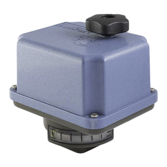
- Page 1 3003 PS (On/Off Version) Operation Instructions...
-
Page 2: Table Of Contents
Contents Technical data ................................... 3 1. Symbols and safety ............................... 3 2. Usage as per specification ............................. 4 3. Storage .................................. 4 4. Operating conditions.............................. 4 4.1 Installation position ............................... 5 5. Function .................................. 5 6. Manual operation ................................. 6 7. Valve mounting ................................ 6 8. Setting of the mechanical stop ............................. 7 9. Setting of the position switches / limit switches ...................... 7 9.1 Setting of the internal limit switches ........................ 8 9.2 Setting of the additional position switches ...................... 8 10. Electric supply ................................ 9 10.1 Wiring diagram .............................. 9 11. Commissioning ................................ 10 12. Service/ Maintenance ............................... 10 12.1 Cleaning ................................ 10 12.2 Spare Parts ................................. 10 13. Appendix ................................... 10 ... -
Page 3: Technical Data
Technical data The technical data of the actuators is specified on the name plate and the data sheets for further information. 1. Symbols and safety Danger signs The following danger signs are used in this operating manual: Caution! There is a general risk of damage related to health and/or properties. Danger! Electrical voltages are present that may lead to death. Life threatening risks may occur due to electrical voltages! Avoid personal or material damages by observing applicable regulations and safety standards! Other notes The motor surface temperature may rise when maintaining, inspecting and repairing the actuator immediately after the operation. There is a danger of burning the skin! Always consult the relevant operating instructions when mounting accessories or operating the actuator with accessories. Connections for signal in‐ and output are double isolated from circuits that can be under dangerous voltage. General dangers of non‐compliance with safety regulations 3003 PS actuators are built at state‐of the art technology and are safe to operate. Despite of this, the actuators may be hazardous if operated by personnel that has not been sufficiently trained or at least instructed, and if the actuators are handled improperly, or not used as per specification. This may cause danger to life and limb of the user or a third party, damage the actuator and other property belonging to the owner, reduce safety and function of the actuator. To prevent such problems, please ensure that these operating instructions and the safety regulations in particular have been read and understood by all personnel involved in the installation, commissioning, operation, maintenance and repair of the actuators. ... -
Page 4: Usage As Per Specification
Before opening the actuator cover, ensure that mains supply is isolated and prevented from unintended re‐connection. Areas that can be under voltage have to be isolated before working on them. Ensure that the actuators are always operated in faultless condition. Any damage or faults, and changes in the operational characteristics that may affect safety, must be reported at once. 2. Usage as per specification 3003 PS quarter turn actuators are exclusively designed to be used as electric valve actuators. They are meant to be mounted on valves in order to run their motors. Any other use is considered to be non‐compliant and the manufacturer cannot be held liable for any damage resulting from it. The actuators can only be used within the limits laid out in the data sheets, catalogues and other documents. Otherwise, the manufacturer cannot be held liable for any resulting damage. Usage as per specification includes the observance of the operating, service and maintenance conditions laid down by the manufacturer. Not to be regarded as usage as per specification are mounting and adjusting the actuator as well as servicing. Special precautions have to be taken while doing this! The actuators may only be used, serviced and repaired by personnel that is familiar with them and informed about potential hazards. The specific regulations for the prevention of accidents have to be observed. Damages caused by unauthorized modifications carried out on the actuators are excluded from the manufacturer's liability. Supply voltage may only be switched on after the proper closure of the main cover or terminal box. Electrical wiring is done to a terminal block under the actuator cover. 3. Storage For appropriate storage, the following instructions have to be met: Only store the actuators in ventilated, dry rooms. Store the actuators on shelves, wooden boards, etc., to protect them from floor moisture. ... -
Page 5: Installation Position
Figure 1: Installation dimensions Outdoor usage: When using actuators in environments with high temperature fluctuations or high humidity, we suggest a heating resistor to be fitted to prevent the build‐up of condensation within the enclosure. 4.1 Installation position The actuator can be installed vertically or horizontally or any position in between. The actuator must not be installed with the cover pointing downwards. Figure 2: Installation positions 5. Function The electric quarter‐turn actuators Series 3003 PS are designed to operate valves with 90° angular motion using the ON/ OFF mode. The 3003 PS actuators are provided with a mechanical interface according to ISO 5211 for valve mounting. The motor torque is transmitted via spur gear, indirectly transmitted onto a double square drive bush. This drive bush is used as a connecting piece between actuator and valve shaft. The 90° rotation is adjustable mechanically +/‐ 5° in one end position. Two adjustable switches limit the rotation in both directions, interrupting the motor current when reaching the adjusted end position. The hand wheel allows manual operation in case of power failure and during adjustment (See pt. 6). ... -
Page 6: Manual Operation
6. Manual operation The hand wheel allows manual operation in case of power failure or during adjustments (Mounting or positioning the valve). For manual operation, the hand wheel has to be pushed down against a spring. Do not exceed the adjusted electrical stroke limits by using the hand wheel. The mechanical stop must be set accordingly to protect the valve. If you don’t observe this warning, the electrical feedback setting will change! Figure 3: Manual operation 7. Valve mounting The 3003 PS actuators are designed with a mechanical interface according to ISO 5211 for valve mounting. The gear contains an exchangeable drive bush to connect the actuator to the valve shaft. Check if the actuator flange suits the valve flange Use standard adapters to adapt to the valve shaft Clean the surface of the connection components, lubricate valve shaft slightly ① Position the actuator on the valve Tighten the screws in a diagonal sequence according to the required torque ② ① Actuator flange ... -
Page 7: Setting Of The Mechanical Stop
8. Setting of the mechanical stop There is one adjustable screw available for setting the mechanical limit of the 90° angular stroke. When setting the mechanical end positions, only the hand wheel may be used. Do not operate the actuator electrically! Remove the protection cap (Figure 5; Pos. 2) from the stop screw. Back off the stop screw counter‐clockwise approx. 5 turns. Move the actuator to the closed position by turning the hand wheel clockwise. Turn stop screw for closed position (Figure 5, Pos. 1) finger tight, then a half turn back. Screw on the protection cap onto the stop screw. ① Stop screw ② Protection cap ② ① Figure 5: Mechanical stop 9. Setting of the position switches / limit switches The limit switches are pre‐adjusted in the factory. ①‐④ A‐D These standard limit switches serve to switch off the motor when the end positions are reached. Additional position switches are free of voltage and serve to ... -
Page 8: Setting Of The Internal Limit Switches
9.1 Setting of the internal limit switches Ensure that the mains supply is secured against accidental switching‐on! The limit switches are pre‐adjusted in the factory. An additional adjustment of the two lower switching cams is normally not necessary. If you wish to adjust the limit switches yourself, please follow the these instructions: Run the actuator by using the hand wheel in direction to the closed position until the required position is reached. Turn the cam of the CLOSE limit switch (Figure 7, Pos. D) with a suitable screw driver (4 mm blade width) clockwise until you hear the micro switch click. Run the actuator by using the hand wheel in direction to the open position until the required position is reached. Turn the cam of the OPEN limit switch (Figure 7, Pos. C) with a suitable screw driver (4 mm blade width) counter‐clockwise until the micro switch is heard to click. Check the switching position and repeat the adjustment if necessary. Switching cam for ① position switch OPEN/ Feedback signal Switching cam for ② position switch A CLOSE/ Feedback signal B ... -
Page 9: Electric Supply
10. Electric supply Switch mains off before starting to work! Connect acc. to wiring diagram on the main frame. Mains connection cables must be dimensioned suitably to accept the maximum current requirement of the actuator and correspond to IEC 227 and IEC 245. The yellow‐green coloured cables may be used only for connecting to earth. When you insert cables through the cable connector, ensure that the maximum bending radius for the cables is observed. 3003 PS electric actuators do not have an internal electrical power switch. A switch or power mains switch has to be provided therefore in plant installation. This should be positioned close to the device and easily accessible to the user; it shall be labelled as the mains isolator switch for the actuator. Plant installation must also provide power surge trips or fuses corresponding to standard IEC 364‐4‐41/ DIN VDE 0100‐410 with protection class 1 for the actuator connections. With protective low voltage 24 VAC the open motor phase can produce voltages between 30‐35 V due to motor generated induction voltage. 10.1 Wiring diagram Figure 8 shows the standard electrical connections. However, the wiring diagram inside the actuator hood is valid for the specific actuator. For any optional extras see the individual wiring diagram in the related service instructions. 230 V, 115 V, 24 V 24 V AC supply DC supply Figure 8: Wiring diagram Two adjustable limit switches are installed to limit the stroke of the actuator, and cut‐off the motor current in the relative direction. 9 ... -
Page 10: Commissioning
PE Earth connection on housing plate has to be connected! 11. Commissioning Drive the actuator into an intermediate stroke position using the hand wheel. Switch the setting signal briefly between OPEN and CLOSE and ensure that the actuator operates in the correct direction. If necessary, reverse the setting signal for OPEN / CLOSE. Drive the actuator, in both directions, using the setting signal until the limit switch cuts‐off. Ensure that the limit switch position is correct. If necessary re‐adjust the limit switches. 12. Service/ Maintenance The actuators are maintenance‐free if used under the operating conditions as stated in the data sheet. The gearboxes are lubricated for lifetime and do not require further lubrication. 12.1 Cleaning The actuators should be cleaned dryly. 12.2 Spare Parts Defective actuators should be returned to Buerkert, to be checked for damages and their possible causes. 13. Appendix Various options are available in order to adapt the actuators to the various service conditions. A list of accessories for each actuator type is shown on the actuator data sheet. Accessories / Options 230 VAC 1~ 115 VAC 1~ 24 VAC 24 VDC Heating ID 774106 ID 774123 Potentiometer 100Ω: ID 774109; 200Ω: ID 774110; 500Ω: ID 774111; 1000Ω: ID 774112; 2000Ω: ID 774113 ...
Need help?
Do you have a question about the 3003 PS and is the answer not in the manual?
Questions and answers