
Subscribe to Our Youtube Channel
Related Manuals for Kärcher AP 100/50 M


Summary of Contents for Kärcher AP 100/50 M
- Page 1 Multi-Functional Cleaning Operating instructions (ENG) MODELS: AP 100/50 M 1.007-080.0 Read these instructions before using the machine. 86343680-L IPX5 07/21/17...
-
Page 2: Machine Data Label
Machine Data Label OVERVIEW This machine is a multi-functional cleaning machine intended for commercial use. The appliance applies chemical at low pressure and uses high pressure to clean with. Then the soiled water is vacuumed back into the recovery tank. Warranty Registration Thank you for choosing our product. -
Page 3: Table Of Contents
Table of Contents Parts Machine Data Label ......2 Control Panel ......26 Table of Contents . -
Page 4: How To Use This Manual
How To Use This Manual This manual contains the following sections: The SAFETY section contains important information regarding hazardous or unsafe practices of the • How to Use This Manual machine. Levels of hazards are identified that could • Safety result in product damage, personal injury, or severe •... -
Page 5: Safety
Safety THIS PRODUCT IS FOR COMMERCIAL GROUNDING INSTRUCTIONS USE ONLY. ELECTRICAL The amp, hertz, and voltage are listed on the data label found on each machine. Using voltages above or below those indicated on the data label will cause serious damage to the motors. -
Page 6: Important Safety Instructions
Safety IMPORTANT SAFETY INSTRUCTIONS When using this machine, basic precaution must always be followed, including the following: READ ALL INSTRUCTIONS BEFORE USING THIS MACHINE. To reduce the risk of fire, electric shock, or injury: Connect to a properly grounded outlet. See Grounding Instructions. Do not leave the machine unattended. -
Page 7: Hazard Intensity Level
Safety The following symbols are used throughout this guide as indicated in their descriptions: HAZARD INTENSITY LEVEL There are three levels of hazard intensity identified by signal words -WARNING and CAUTION and FOR SAFETY. The level of hazard intensity is determined by the following definitions: WARNING - Hazards or unsafe practices which COULD result in severe personal injury or death. -
Page 8: Safety Label Location
Safety SAFETY LABEL LOCATION The following WARNING LABEL(S) are found on your cleaning unit. These labels point out important Warnings and Cautions which should be followed at all times. Failure to follow warnings and cautions could result in fatality, personal injury to yourself and/or others, or property damage. Follow these instructions carefully! DO NOT remove these labels. -
Page 9: Operations
Operations Technical Specifications ITEM DIMENSION/CAPACITY Electrical 120V, 14A, 60HZ Electric Pump Motor 1/2hp, 1750rpm Solution Pump 700psi (48 bars), Axial plunger Electric Vacuum Motor 2stage, 1.25hp (2.80m3/min.) Waterlift 82 in. (208 cm) Solution Capacity 29 gallons (111L) Recovery Capacity 19 gallons (70L) Wheels -Front (2) 6 in. -
Page 10: How The Machine Works
Operations How the Machine Works The function of the chemical system is to dispense chemical into the clean water system. The chemical This machine is a multi-functional cleaning machine system consists of the chemical reservoir, chemical cap intended for commercial use. The appliance applies and a chemical-metering selector. -
Page 11: Components
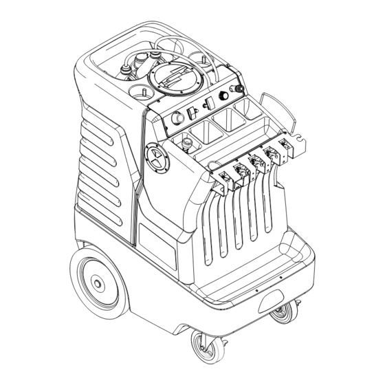
Operations Components 1. Control Panel 7. Recovery Tank Lid 2. Solution Tank 8. Recovery Tank Drain Hose 3. Solution Tank Lid 9. Chemical Siphon Caps 4. Solution Tank Drain Hose 10. Electrical Cord 5. Solution Tank Fill Hose 11. High Pressure Hose Storage 6. -
Page 12: Controls
Operations Controls 1. Caster Lock 5. Solution Accessory Tool Hook-Up 2. Chemical Selector and Metering Valve 6. Vacuum Accessory Tool Hook-Up 3. Pump Circuit Breaker 7. Vacuum Circuit Breaker 4. Pump Switch/Pump Chemical Switch 8. Vacuum Switch 86343680 AP 100-50 M... - Page 13 Operations 1. CASTER LOCK Locks the wheels in place to keep the machine from moving. 2. CHEMICAL SELECTOR AND METERING VALVE Meters the amount of chemical being dispensed and selects between chemical A or B and turns chemical off. 3. PUMP CIRCUIT BREAKER 8 Amp.
-
Page 14: Filling The Machine
Operations Filling The Machine Do not put defoamer, solvents spotter or prespray chemicals in the solution tank. 3. Attach the adapter cap and intake hose to the Chemical bottle. Refer to the Chemical Label for the desired dilution. 1. Always use gloves and eye protection. Never spray solution towards people. - Page 15 Operations 7. Turn Chemical off. Pressure clean by rinsing surfaces at high pressure. 5. Always Spray chemical using low pressure 8. Use Squeegee to remove standing water. 6. Use brush or grout tool for heavy soiled areas. 86343680 AP 100-50 M...
- Page 16 Operations UNLOADER VALVE 11. From the factory your machine is set to spray at 600 psi (high pressure) and 200 psi (low pressure w/chemical injection). To lower pressure turn the unloader valve knob counter clockwise. The valve 9. Store and secure hoses and tools neatly. is accessed from below the machine through a hole in the bottom frame.
-
Page 17: Machine Operation
Operations Machine Operation Only use chemicals approved for use with this machine. Use of non-compatible chemicals may cause machine damage and will not be covered under the warranty. Carefully read ingredients on manufacturer's label before using any product in this machine. Care must be exercised in the use of all chemicals. -
Page 18: Maintenance
Maintenance 5. Pump 1. Float Shut-Off 6. Adjustable Unloader Valve 2. Strainer 7. Injector Assembly & Coil 3. Circuit Breakers 4. Vacuum Motor 86343680 AP 100-50 M... -
Page 19: Float Shut-Off
Maintenance Float Shut-off Circuit Breakers The float shut-off is located inside the recovery tank. Circuit breakers interrupt the flow of power in the event The purpose of the float shut-off is to notify the user of an electrical overload. When a circuit breaker is that the recovery tank is full. -
Page 20: Vacuum Motor
Maintenance Vacuum Motor Vacuum Motor Carbon Brushes (Refer to vacuum group in the parts section of manual). End Cap ONLY QUALIFIED MAINTENANCE PERSONNEL WARNING: The green ARE TO PERFORM THE FOLLOWING REPAIRS. ground wire must be Carbon attached for safe operation. Brushes Vacuum Motor Replacement See wiring diagram. -
Page 21: Solution Pump Replacement
Maintenance Pump Regulating Unloader ONLY QUALIFIED MAINTENANCE PERSONNEL ONLY QUALIFIED MAINTENANCE PERSONNEL ARE TO PERFORM THE FOLLOWING REPAIRS. ARE TO PERFORM THE FOLLOWING REPAIRS. Solution Pump Replacement Unloader Replacement 1. Turn off all switches and unplug machine. 1. Turn off all switches and unplug machine. 2. -
Page 22: Periodic Maintenance
Maintenance Periodic Maintenance Daily/regular Maintenance Twice a month, flush a white vinegar solution (one quart Before making any adjustments to the machine, vinegar to two gallons of water) or anti-browning disconnect the power cord from the electrical source. solution (mixed as directed) through the machine. This 1. -
Page 23: Trouble Shooting
Maintenance Trouble Shooting PROBLEM CAUSE SOLUTION Dead electrical circuit Check building circuit breaker or fuse box Loss of Power Faulty power cord Replace GFI breaker is tripped Reset breaker on power cord Equipment not grounding Follow grounding instructions exactly Receptacle not grounded Contact an electrician to check building’s wiring Electrical shock Have a trained service technician check machine’s... - Page 24 Notes: 86343680 AP 100-50 M...
-
Page 25: Parts
Parts PARTS 86343680 AP 100-50 M... -
Page 26: Control Panel
Control Panel 86343680 AP 100-50 M... - Page 27 Control Panel SERIAL NO. PART NO. PRV NO. DESCRIPTION NOTES: FROM 86233090 20016 CLAMP, 1/4 ID HOSE 86282280 39634 HOSE, 1/4 ID NYLOCBRAID X 23" 86402500 270699 CAP CHEM FEED W/DIP TUBE, YLW 86258930 84187 VALVE, CHEMICAL METERING 86005700 57104 NUT, 10-32 W/STAR WASHER PLTD 86001940 14635...
-
Page 28: Decals
Decals 86343680 AP 100-50 M... - Page 29 Decals SERIAL NO. PART NO. PRV NO. DESCRIPTION NOTES: FROM 86396600 LABEL, COMPASS, CONTROL 86242230 500009 LABEL, WARNING EXPLOSION HAZ'D 86332740 LABEL, KARCHER PROFESSIONAL 86014480 LABEL, KARCHER, FRONT 86305190 INSTRUCTION CARD 86002870 27417 CORD, 1/8" X 12" 86343680 AP 100-50 M...
-
Page 30: Solution Tank
Solution Tank 86343680 AP 100-50 M... - Page 31 Solution Tank SERIAL NO. PART NO. PRV NO. QTY DESCRIPTION NOTES: FROM 86275800 70546 SCR, 8 X 3/4 PFHT/S BLK ZINC 86334470 DECK, PLATE ASM, 4", YLW 86333450 TANK, SOL CMPS2K 86239680 41476 HOOK, HOSE STORAGE 86006950 70532 SCR, 10-32 X 1/2 PPHMS BLK NP 86224730 73939 SPRING, COMP, 12MM OD X 12.7MM...
-
Page 32: Solution Injector Assembly
Solution Injector Assembly 86343680 AP 100-50 M... - Page 33 Solution Injector Assembly SERIAL NO. PART NO. PRV NO. DESCRIPTION NOTES: FROM 86302410 QD, COUPLER, FOSTER 25FS 86302570 HOSE, PULSE, 3/8F X 3/8F X 45" 86197730 78024 TEE, 1/4 BRANCH 86180460 12-800356 ELL,1/4PX1/4T 45DEG BR 86303760 VALVE, SOLENOID, 1/4F 700PSI 86303850 COIL, 115V, SOLENOID 86197300...
-
Page 34: Solution Pump Assembly
Solution Pump Assembly 86343680 AP 100-50 M... - Page 35 Solution Pump Assembly SERIAL PART NO. PRV NO. DESCRIPTION NOTES: NO. FROM 86302790 HOSE, PULSE, 1/4MSWL X 3/8NPT X 30" 86197610 40034 HOSEBARB, 3/8MPTX3/8 90D DL 86233090 20016 CLAMP, 1/4 ID HOSE 86302780 HOSE, BRAIDED, 3/8ID X 16" L 86302820 PUMP, PUMPTEC, 700PSI 86197540 40013...
-
Page 36: Solution Pump
Solution Pump 86343680 AP 100-50 M... - Page 37 Solution Pump SERIAL NO. PART NO. PRV NO. DESCRIPTION NOTES: FROM 86240430 40083 HOSEBARB, 3/8 MPT X 3/8 NYLON 86233090 20016 CLAMP, 1/4 ID HOSE 86197910 40022 HOSEBARB, 1/2MPT X 1/2 POLY DL 86233150 20042 CLAMP, 3/8 HOSE (D-SLOT) 86010630 87013 WASHER, 1/4 ID X 5/8 OD SS 86005810...
-
Page 38: Recovery Tank
Recovery Tank 86343680 AP 100-50 M... - Page 39 Recovery Tank SERIAL NO. PART NO. PRV NO. DESCRIPTION NOTES: FROM 86277040 70781 SCR, 5/16-18 X 1/2 HHCS SS NP 86010670 87029 WASHER, 5/16 FLAT SS 86070510 140659 BRKT, TANK MOUNT 86334490 DECK PLATE ASM, 6", YLW 86275800 70546 SCR, 8 X 3/4 PFHT/S BLK ZINC 86004000 35255 GASKET, TANK LID...
-
Page 40: Vacuum
Vacuum 86343680 AP 100-50 M... - Page 41 Vacuum SERIAL NO. PART NO. PRV NO. DESCRIPTION NOTES: FROM 86237870 35270 GASKET, 5.0 OD X 2.38 ID X .25T 86002380 20046 CLAMP, 2.25" WORM GEAR 86281180 39298 HOSE, 2.0 VAC EXHAUST X 17" 86240240 39697 HOSE, 3.15 ID X 7.0L VENT 86233260 20092 CLAMP, 3.5"...
-
Page 42: Wheels & Frame
Wheels & Frame 86343680 AP 100-50 M... - Page 43 Wheels & Frame SERIAL NO. PART NO. PRV NO. DESCRIPTION NOTES: FROM 86309790 WHEEL, 12" X 2.25" (1*) 86001660 HUBCAP, 5/8" SHAFT (1*) 86270830 57023 NUT, 5/16-18 HEX NYLOCK SS 86078800 620001 PLATE MOUNT CASTER 86010670 87029 WASHER, 5/16 FLAT SS 86276780 70728 SCR, 5/16-18 X 3/4 HHCS SS...
-
Page 44: Tools - Standard
Tools - Standard 86343680 AP 100-50 M... - Page 45 Tools - Standard SERIAL NO. PART NO. PRV NO. DESCRIPTION NOTES: FROM 86257660 02478 TOOL, HAND SQUEEGEE 86257650 02477 TOOL, SCRUB BRUSH HANDLE 86257640 02475 TOOL, GULPER 86257670 02479 TOOL, TILE BRUSH 86257680 02480 TOOL, ALUMINUM WAND 86257620 02473 TOOL, WHEELED SQUEEGEE 86301890 LANCE, TUBE, 1/4", 14"...
-
Page 46: Wiring Diagram
Wiring Diagram GRN/YEL POWER POWER CORD POWER CORD CONNECTION PUMP MOTOR VACUUM MOTOR SOLENOID GRN/YEL GRN/YEL 5 WIRE HARNESS GRN/YEL VACUUM PUMP VACUUM PUMP CIRCUIT CIRCUIT SWITCH SWITCH BREAKER BREAKER 86343680 AP 100-50 M... - Page 47 Wiring Diagram SERIAL NO. PART NO. PRV NO. DESCRIPTION NOTES: FROM 86305020 HARNESS, MAIN 86305060 CORD SET, 14/3 X 31 86308000 WIRE, 6" BLK/14 76050 X 76029 88305070 WIRE, 2", BLK/14 76050 X 76029 86268570 88401 WIRE, 3", BLK/14 76029X 76029 86268180 88184 WIRE, 8", GRN/18 76008 X 76008...
-
Page 48: Vacuum Hose Rack - Option
Vacuum Hose Rack - Option 86343680 AP 100-50 M... - Page 49 Vacuum Hose Rack - Option SERIAL NO. PART NO. PRV NO. DESCRIPTION NOTES: FROM 86240630 49499 HOSE RACK 86276600 70696 SCR, #10 X 3/4 PTHSMS SS 86006590 70088 SCR, 10-32 X 1/2 PPHMS SS NP 86275210 70384 SCR, 1/4-20 X ½ PHTR BLK DL 86270250 03-000133 CLAMP, 1/4X1/4 BLT VIN DP 86005680...
-
Page 50: Tools - Grout Cleaner - Option
Tools - Grout Cleaner - Option 86343680 AP 100-50 M... - Page 51 Tools - Grout Cleaner - Option SERIAL NO. PART NO. PRV NO. DESCRIPTION NOTES: FROM 86200820 270-11A NIPPLE, 1/8 FPT QD MALE BRASS 86247720 56032 NIPPLE, 1/8 CLOSE 86194160 11-800133 TEE, 1/8 BR 86240190 39639 HOSE, 1/8 MPT X 1/4 FPT X 12L 86090230 87015 WASHER, 9/16 ID X 1.06 OD SS...
-
Page 52: Tools - High Pressure Wand - Option
Tools - High Pressure Wand - Option 86343680 AP 100-50 M... - Page 53 Tools - High Pressure Wand - Option SERIAL NO. PART NO. PRV NO. DESCRIPTION NOTES: FROM 86005580 56012 NIPPLE, 1/4 FPT QD 86240210 39641 HOSE, 1/8 MPT X 1/4 MPT X 7 L 86274410 70195 SCR, 10-32 X 1.25 PPHMS SS 86258950 84189 VALVE, 500 PSI W/ CLAMP...
-
Page 54: Tools - Carpet Tool - Option
Tools - Carpet Tool - Option 86343680 AP 100-50 M... - Page 55 Tools - Carpet Tool - Option SERIAL NO. PART NO. PRV NO. QTY DESCRIPTION NOTES: FROM 86200820 270-11A NIPPLE, 1/8 FPT QD MALE BRASS 86240220 39642 HOSE, 1/8 MPT X 1/8 MPT 86296220 ELBOW, 1/8 FPT 86305440 WASHER, .45ID X .87X .20THK NYL 86305450 WASHER, .40ID X .87OD X .060THK SST 86241710...
-
Page 56: Chemical Lock - Option
Chemical Lock - Option 86343680 AP 100-50 M... - Page 57 Chemical Lock - Option SERIAL NO. PART NO. PRV NO. DESCRIPTION NOTES: FROM 86070520 140660 BRKT, CHEMICAL LOCK 86343680 AP 100-50 M...
-
Page 58: Suggested Spare Parts
Suggested Spare Parts SERIAL NO. PART NO. PRV NO. DESCRIPTION NOTES: FROM 86241930 47419 KIT, SQUEEGEE TOOL BLADES 86305460 STRAINER, 3/8FPT 80 MESH 86135320 140687 BRUSH SET, 120V VAC 86028720 53266 VAC MOTOR ASM, 115V W/ TERM 86002010 14942 BOOT, 3/8 CIRCUIT BREAKER 86215670 140839 BREAKER, 8A VDE CIRCUIT... -
Page 59: Serial Numbers
Serial Numbers REF. MODEL: SERIAL # 10070800000036 86343680 AP 100-50 M...
Need help?
Do you have a question about the AP 100/50 M and is the answer not in the manual?
Questions and answers