
Related Manuals for Cerio OW-400 2N Series


Summary of Contents for Cerio OW-400 2N Series
- Page 1 CERIO Corporation CenOS 5.0 User Manual OW-400 2N/4N Series eXtreme High Power WiFi6 Dual-Radio Outdoor PoE Bridge/AP OW-400 2N10 OW-400 4N00 OW-400 2N18 V1.0a V1.2...
-
Page 2: Table Of Contents
Content Device and Software Configuration ......................6 1-1. Device appearance ........................6 1-2. Setup Preparation of AP ......................8 1-3. Login Web Page ........................10 Operating Mode Introduction ........................11 2-1. Access Point Mode (Default Mode) ..................11 2-2. Client Bridge + Repeater Mode ....................12 2-3. - Page 3 4-3-2. Local User ........................... 38 4-3-3. OAuth 2.0 ......................... 38 #Sample for Google OAuth2.0 setup ..................... 39 #Sample for Facebook OAuth2.0 setup ....................42 4-3-4. POP3/IMAP Server ......................45 4-3-5. Customize ........................45 4-3-6. Language ......................... 47 4-3-7. Walled Garden......................... 48 4-3-8.
- Page 4 5-4-4. WMM Setup ........................74 5-4-5. Station Setup ........................76 5-4-6. Station Porfile Setup ....................... 77 5-4-7. Repeater AP Setup ......................78 5-4-8. MAC Filter Setup ......................... 82 5-4-9. 802.11r Fast Roaming ..................... 83 WISP Mode .............................. 85 6-1. Change Setup mode ......................... 86 6-2.
- Page 5 System Log .......................... 133 10. [ Other technical documents] ........................134 10-1. Point to Point / Multi-Point for WDS settings ................134 10-2. Apply CERIO web authentication login page sample ..............135 Appendix A. WEB GUI Valid Characters ....................141 V1.0a V1.2...
-
Page 6: Device And Software Configuration
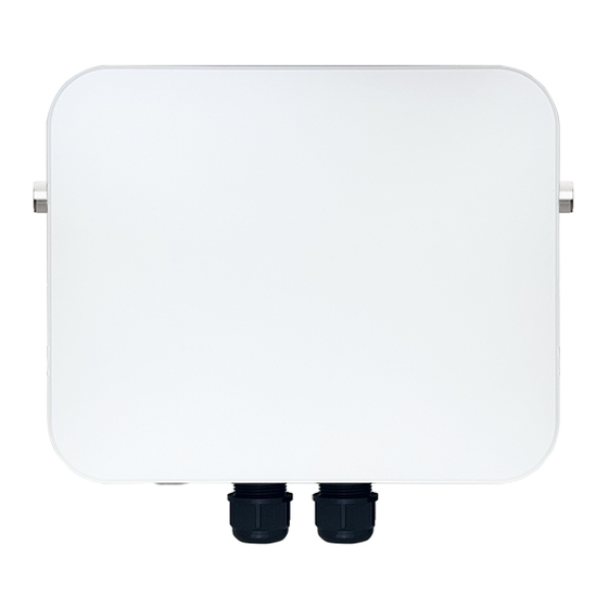
Device and Software Configuration Device appearance 1-1. External for 2.4GHz External for 2.4GHz N-Type Connecter N-Type Connecter External for 5GHz External for 5GHz N-Type Connecter N-Type Connecter 6KV Lightning Protection Aluminum Adjustable Surge Grounding Port Bracket Holes Metal Corrosion-Resistant Casing Pressure Vent Function Port 1G ETH1 / PoE in... - Page 7 External for 2.4GHz External for 2.4GHz N-Type Connecter N-Type Connecter Built in 2x2 10 dBi /18dBi 5GHz Directional Panel Antenna 6KV Lightning Protection Aluminum Adjustable Surge Grounding Port Bracket Holes Metal Corrosion-Resistant Casing Pressure Vent Function Port 1G ETH1 / PoE in 2.5G ETH2 / PoE in Reset Button Outdoor PoE Bridge/AP:...
-
Page 8: Setup Preparation Of Ap
Setup Preparation of AP 1-2. Please PC link to Device used cat5/6 Ethernet cable. The following setup uses a Windows PC, user OS may vary. Step 1: Please click on the computer icon in the bottom right window, and click “Open Network and Internet settings”... - Page 9 Step 4: In Properties page to setting IP address, please find “Internet Protocol Version 4 (TCP/IPv4)” and double click or click “OK” button. Step 5 : Select “Use the following IP address”, and fix in IP Address : 192.168.2.# ex. The # is any number by 1 to 253 Subnet mask : 255.255.255.0 And Click "OK"...
-
Page 10: Login Web Page
1-3. Login Web Page Launch as web browser to access the web management interface of system by entering the default IP Address, http://192.168.2.254, in the URL field, and then press Enter. Default login Usermane is〝root〞and Password is〝default〞. V1.0a V1.2... -
Page 11: Operating Mode Introduction
Operating Mode Introduction Access Point Mode (Default Mode) 2-1. Please click on System ->Mode Setup and choose Access Point Mode It can be deployed as a traditional fixed wireless Access Point It allow wireless clients or Stations ( STA ) to access ... -
Page 12: Client Bridge + Repeater Mode
Client Bridge + Repeater Mode 2-2. Please click on System ->Mode Setup and choose Client Bridge Mode It can be used as a Client Bridge + Repeater AP to receive wireless signals over last mile applications, helping WISPs deliver wireless broadband Internet service to new residential and business customers. -
Page 13: Wisp + Repeater Ap Mode
Note: If Client Bridge used 5GHz connection to AP station then Repeater AP only use 2.4GHz. WISP + Repeater AP Mode 2-3. Please click on System ->Mode Setup and choose WISP Mode It can be used as an WISP (Wireless Internet Service Provide) to receive wireless signals over last mile ... -
Page 14: Cap Mode (Centralizes Access Point)
application, helping WISPs deliver wireless broadband Internet service to residents and business customers. In the WISP (CPE) mode, the CenOS 5.0 AP is a gateway enabled with NAT and DHCP Server functions. The wired clients connected to APs are in different subnet from those connected to Main Base Station, and, in WISP (CPE) mode, it does not accept wireless association from wireless clients. -
Page 15: System Configuration
System Configuration 3-1. Management Please click on System ->Management and choose System Language. System Language:Administrator can select system language for English and Traditional Chinese System Information:Administrator can set the system name / Description and Location. V1.0a V1.2... - Page 16 Root Password:Administrator can change system login password. Control:Administrator can select enable or disable of the LED flashes. Ping Watchdog:Ping Watchdog helps administrator to automatically reboot the system when its not working properly. Interval:Ping interval of time. Delay:After system start, the set time value starts execution Ping watchdog.
-
Page 17: Configure Time Server
Please enter IP address and port of remote syslog server. Auto Reboot:The functions can Auto-reboot the system by Date/time management. Daily : Setting time to system reboot. Weekly : Setting frequency (ex. Weekly) and time of system reboot. ... -
Page 18: Snmp
System time Mode:Administrator can select NTP Server or Manual. NTP Server: System can auto update the system time. Administrator needs setting as NTP Server. Default NTP Server:Administrator can select NTP Server. Server:Administrator can setting as NTP Server. ... - Page 19 SNMP V2c Function Active:Administrator can select Enable or Disable the service. Community:Set a community string to authorize read-only access. Community:Set a community string to authorize read/write access. SNMP V3 Function Active:Administrator can select Enable or Disable the service. ...
-
Page 20: Configure Time Policy
trap messages or notices send by the system. 1~4:Enter the IP addresses of the remote hosts to receive trap messages. 3-4. Configure Time Policy Please click Edit button to setting Time Policy rules Comment: Enter the description of Time Policy rule. ... -
Page 21: Access Point Mode
Administrator can set time for week / start time and end time. Click “Save” button to save your changes. And click “Reboot” button to activate your changes Access Point mode When AP mode is chosen, the system can be configured as an Access Point. This section provides detailed explanation for users to configure in the AP mode with help of illustrations. -
Page 22: Vlan Setup
For the first time after switching modes, always perform access management on the LAN default IP address of 192.168.2.254 2. Cerio’s dual-band wireless base station supports 16 VLANs and 32 SSIDs (each frequency band supports 16 SSIDs). -
Page 23: Network Setup
# Network Setup Administrator can click Network button to set VLAN network functions. VLAN Mode:Administrator can select Enable or disable for the VLAN Network. IP Mode:Administrator can select enable or disable function for VLAN IP. IP Address/ NetMask:Administrator can set IP address and netmask for the VLAN. ... -
Page 24: Network Pull-Down Menu
802.1d Spanning Tree : The spanning tree network protocol provides a loop free topology for a bridged LAN between LAN interface and 8 WDS interfaces from wds0 to wds7. The Spanning Tree Protocol, which is also referred to as STP, is defined in the IEEE Standard 802.1d Control Port:Administrator can select one of the VLAN as managed AP. - Page 25 Start IP: Set Start IP address for DHCP Service. End IP: Set End IP address for DHCP Service. Netmask: Set IP Netmask, the default is 255.255.255.0 Gateway: Set Gateway IP address for DHCP Service. DNS(1-2) IP : Set DNS IP address for DHCP Service. ...
-
Page 26: Bandwidth Control
Administrator can view IP address used status of client users on each DHCP Server. Static Lease IP Setup:Administrator can set be delivered fixed IP address to the users. Comment: Enter rule description. IP Address: Enter access point IP. ... -
Page 27: Radio 0(2.4G)/1(5G) Access Point Setup
QoS Rule List: Administrator can set bandwidth limit by IP/MASK, IP Range, Port(Service), SIP, RTP/RTSP, WEB protocol , each VLAN can set 10 bandwidth management rule. Click “Save” button to save your changes. Then click Reboot button to activate your changes. Radio 0(2.4G)/1(5G) Access Point Setup 4-2-3. - Page 28 【Supports 128 users to access at the same time.】 Security Type: Select the desired security type from the drop-down list; the options are Open System, WPA-PSK/WPA2-Personal, WPA/WPA2-Enterprise, WPA3 and 802.1x Notes: The WEP encryption mode is currently known to be not the most secure wireless encryption method, and will not be able to support 802.11ac/ax.
- Page 29 Note: If you choose to use WEP encryption mode, please enter the corresponding WEP key value according to the following requirements. 64bits: 10 groups of Hexadecimal characters (0~9, A~F and a~f can be used) 5 groups of ASCII characters (0~9, A~Z and a~z can be used) 128bits: 26 groups of Hexadecimal characters (0~9, A~F and a~f can be used) 13 groups of ASCII characters (0~9, A~Z and a~z can be used)
- Page 30 Group Key Update Interval: The time interval is for re-keying GTK (broadcast/multicast encryption keys) in seconds. Enter the time-length required; the default time is 600 seconds. Pass Phrase: Enter the ESSID pass phrase. Push Button: Administrator can used WPS function to link WiFi client. If enabled, ...
- Page 31 WPA3 : The 802.11ax peer-to-peer entity authentication mode is different from the Pre-Shared Key . SAE Password:When the administrator sets this virtual wireless network SSID to use WPA3 calculation, the SAE connection password must be at least 8 characters. SAE PWE:Optionally enable the SAE PWE (Password Element) function, before exchanging ...
-
Page 32: Mac Filter
Radius Port: The port number used by Authentication RADIUS server. Use the default 1812 or enter port number specified. Radius Secret: The secret key for system to communicate with Authentication RADIUS server. Support 1 to 64 characters. Filter 4-2-4. -
Page 33: 802.11R Fast Roaming Setup
802.11r Fast Roaming Setup 4-2-5. The dual band Access Point supports 802.11r/802.11k function for 2.4G and 5G radio. 802.11r, which is the IEEE standard for fast roaming, introduces a new concept of roaming where the initial handshake with the new AP is done even before the client roams to the target AP. If this feature is enabled when using 802.11r fast roaming, the wireless user equipment must support 802.11k functionality to work properly Mobility Domain: MDID is used to indicate a group of APs (within an ESS, i.e., sharing the same... - Page 34 This setting must be 2-octet of hex string codes. For example, enter 8c4d R0 Key Lifetime: Default lifetime of the PMK-RO in minutes, the default is 10000, administrator can setting 1~65535. Reassoc deadline: Reassociation deadline in time units (TUs / 1.024 ms; range 1000~65535). The ...
-
Page 35: Authentication
R1 Identifier: Enter Shared identifier. 128-bit Key: Enter Shared Key of 128 bit. Click “Save” button to save your changes. Then click Reboot button to activate your changes. Authentication 4-3. This function is for Web Authentication in Access Point mode, the function is for Web Authentication. It supports authentication for local users / RADIUS Server / OAuth2.0 and Guest. - Page 36 Multiple Login:Administrator can set one account to multiple users simultaneously login and the users can set limit.( 0 = not limited) Login Timeout:After account login for some time no traffic, system will automatic timeout for account. Administrator can enter a time(Minutes). Redirect URL :After the success of the login, system will redirect to URL.
-
Page 37: Guest
RADIUS:Authentication support remote RADIUS Server. Administrator can enter security ※ information for remote RADIUS Server. Click “Save” button to save your changes. Then click Reboot button to activate your changes. 4-3-1. Guest Administrator can enable or disable guest authentication. If enabled, the administrator can set guest Count Limit / login time and type and flow control. -
Page 38: Local User
Login Type : One Time: Login to start counting until the end of time. Multiple Times: logout time will stop counting until the next re-login to time start counting. Count Limit: Administrator can set guest limit. Login Time: Within a certain timeframe with no traffic, the system will auto logout. -
Page 39: Sample For Google Oauth2.0 Setup
Provider :Display authentication server. The system default use authentication server for Google and Facebook. #Sample for Google OAuth2.0 setup Please complete the application on the Google website to receive an account ID and password, follow the steps below. Step.1 Please go to the Google Developers Console page and create a project (Reference https://developers.google.com/identity/protocols/OAuth2) - Page 40 Step.3 Select web application in the “Application Type” section and set “Restrictions” URL. Step.4 Set Authorized JavaScript origins and Authorized redirect URLs (important) Administrator must set login URL in the device function. After complete set of login URL go to the “Restrictions”...
- Page 41 After complete set of login URL go to the “Restrictions” function in web page. Copy and paste the login URL from the system display into the “Restriction” page on the Google Developer website. Google Authorized JavaScript origins URL is http://domain0.login.com (same as Login URL) ...
-
Page 42: Sample For Facebook Oauth2.0 Setup
#Sample for Facebook OAuth2.0 setup Please complete the application on the Facebook website to receive an account ID and password, follow the steps below. Step.1 Please to Facebook developer’s page and add a New App Step.2 Select WWW function Step.3 Administrator must set www for your information. - Page 43 Step.5 Select Platform for “Website” Step.6 Enter URL is http://domain0.login.com/login/index.cgi?cgi=CALLBACK Administrator must set login URL in the device function. After complete set of login URL go to the “Facebook function in web page. Follow the steps below to set login URLs Site URL”...
- Page 44 After complete set of login URL go to the “Facebook function in web page. Copy and paste Site URL” the login URL from the system display into the “ page on the Facebook website. Site URL” Step.7 Click Advanced function to enable the “Native or desktop app?”...
-
Page 45: Pop3/Imap Server
4-3-4. POP3/IMAP Server The purpose of this integrated function is to allow clients to link a POP3 server for receiving emails from a remote server. Service: Administrator can choose Enable or Disable the PoP3 authentication. Display Name:Set the “Display Name” based on the appropriate POP3 user or client. ... - Page 46 Page Setup Template:Administrator can select Enable or disable. Select enable to active default Login Page Select disable to active HTML Source code window for customization V1.0a V1.2...
-
Page 47: Language
Sample: See sample login page below that is customized by html coding (sample login page html code templates are available on Cerio website) The following function uses the enabled Template Multiple Language:Administrator can select enable or disable multiple language for login page. -
Page 48: Walled Garden
Click “Create New Language” button go to add or edit language for login page. Language: Set description of language. Default Language: Display default language. 4-3-7. Walled Garden This function provides certain free services or advertisement web pages for users to access the websites listed before login and authentication. -
Page 49: Bulk Mac Address
Device Name: Enter Device or Users Name. IP Address: Enter used IP Address of Device or Users PC. MAC Address: Enter MAC Address of Device or Users PC. Click “Save” button to save your changes. Then click Reboot button to activate your changes.. Bulk MAC Address 4-3-9. -
Page 50: Profile
4-3-10. Profile Administrator can backup current authentication configuration and login page for HTML Source code. But also can recover. Click “Save” button to save your changes. Then click Reboot button to activate your changes. RADIUS Server 4-4. Service:Administrator can select Enable or disable the function. ... -
Page 51: Wireless Configuration
User Name:Create users name for RADIUS account. Password:Enter password for user name. Export User File:Administrator can export account list in RADIUS Server. Import From PC:Administrator can import account list to the RADIUS Server. Wireless Configuration 4-6. Basic Setup 4-6-1. - Page 52 General Setup Address:Display 2.4G WiFi MAC address. Country:Administrator can select country: US or EU or Taiwan. Band Mode:Administrator can select 2.4G Band for 802.11b、802.11b/g、802.11b/g/n、 802.11n. or 802.11ax, The default is 802.11ax Auto Channel:Administrator can Enable or Disable the function. If disabled, the WiFi channel will ...
- Page 53 HP Physical Mode TX/RX Stream : The CenOS 5.0 AP support 2TX/2RX streams. Administrator can select 1 or 2 TX/RX. The default is 2TX/2RX. Channel Bandwidth:The "20/40” MHz option is usually best. The other option is available for ...
-
Page 54: Radio 1 (5G) Basic Setup
Aggregation Frames: Set frames size of Aggregation. Aggregation Size: Set aggregation size Basic Setup 4-6-2. Radio 1 (5G) General Setup MAC Address: Display 5G WiFi MAC address. Country: Administrator can select country: US or EU or Taiwan. ... - Page 55 Distance: When the "Distance" button is clicked, the point-to-point bridge distance can be entered. The system will automatically calculate the ideal reference value for the Slot Time and ACK Timeout. The input distance is calculated in units (meters). ACK Timeout : When waiting for the "ACKnowledgment frame" interval is too long to be received, ...
-
Page 56: Advanced Setup
also increase error rate in some installations, due to increased sensitivity to radio-frequency reflections. Select the option that works best for your installation. Aggregation: By default, it's “Enabled”. Select “Disable” to deactivate Aggregation. A part of the 802.11n standard (or draft-standard), it allows sending multiple frames per single access to the medium by combining frames together into one larger frame. - Page 57 “Beacon”. Beacon is broadcast to all the stations, provides the basic information of AP such as SSID, channel, encryption keys, signal strength, time stamp, support data rate. All the radio stations received beacon recognizes the existence of such AP, and may proceed next actions if the information from AP matches the requirement.
-
Page 58: Wmm Setup
the Threshold value. By default, RTS is disabled in a normal environment supports non-jumbo frames. Short Preamble: By default, this function is “Enabled”. Disabling will automatically use the Long 128-bit Preamble Synchronization field. The preamble is used to signal "here is a train of data coming"... - Page 59 Please click on Wireless -> WMM Setup AC Type: Data Transmitted Queue Priority Description AP to Clients AC_BK Background High throughput. Bulk data that requires maximum throughput and is not time-sensitive is sent to this queue (FTP data, for example). AC_BE Best Effort Medium...
-
Page 60: Wds Setup
63, 127, 255, 511, or 1024. The value for "cwmax" must be higher than the value for "cwmin". AIFS:The Arbitration Inter-Frame Spacing Number specifies a wait time (in milliseconds) for data frames TxOP Limit: Transmission Opportunity is an interval of time when a WME AP has the right to ... - Page 61 WDS Setup: Administrator can select Enable or Disable. Security Type: Enable or Disable AES 128bit encryption function. V1.0a V1.2...
-
Page 62: Wds Status
WDS considerations 1. When two wireless APs want to use WDS connection, the channels of the two must be the same. 2. If the two base AP stations are A and B, the WDS Client Setup of station A needs to set the wireless MAC address of station B, and the WDS Client Setup of station B needs to set the wireless MAC address of station A. -
Page 63: Client Bridge Mode
Client Bridge Mode If the administrator needs to switch to Client Bridge mode, Please click "System"-> " Mode Setup " to change Client Bridge mode. 5-1. Change Setup Mode This section provides detailed explanation for users to configure in the Client Bridge Mode and Repeater AP function with help of illustrations. - Page 64 Static IP: IP address: The IP address is 192.168.2.254 Netmask: The default Netmask is 255.255.255.0 Gateway: The default Gateway IP Address is 192.168.2.1, Please check your Gateway IP and change. DNS: Enter IP address of domain name service. ...
-
Page 65: Configure Dhcp Setup
Click “Save” button to save your set function. Then click “Reboot” button to activate your changes. Configure DHCP Setup 5-3. The DHCP Service function in the Client Bridge device can select a separate IP Address range within the same network segment of the source AP, and allocate those IP Addresses to connecting clients. Start IP / End IP: Specify the range of IP addresses to be used by the DHCP server when ... - Page 66 Netmask: The netmask default is 255.255.255.0. Gateway: Enter source gateway IP address. DNS1: Enter IP address of the first DNS server; this field is required. DNS2: Enter IP address of the second DNS server; this is optional ...
-
Page 67: Wireless General Setup
Static Lease IP List: Display users list of static IP address. Click “Save” button to save your set function. Then click “Reboot” button to activate your changes. Wireless General Setup 5-4. Basic Setup 5-4-1. Radio 0 (2.4G) General Setup Address:Display 2.4G WiFi MAC address. - Page 68 Auto Channel:Administrator can Enable or Disable the function. If disabled, the WiFi channel will be fixed to the manually selected channel. Channel:There are different options for wireless operation modes in regions, which can be used for Upper or Lower extension. Power:Administrator can control the WiFi Tx output power.
-
Page 69: Radio 1 (5G) Basic Setup
of WLAN.The MCS coding value will affect the main factor of the communication rate and corresponds to the channel bandwidth. MAX MCS: Maximum MCS compile set value. The Max MCS value must be greater than the Min MCS value. Short GI :... - Page 70 Band Mode: Administrator can select 5G Band for 802.11a、802.11a/n、802.11n、802.11ac. or 802.11ax. The default is 802.11ax Auto Channel: Administrator can Enable or Disable the function. If select disabled function the WiFi channel can be manually fixed. Channel:There are different options for wireless operation modes in regions. ...
-
Page 71: Advanced Setup
Channel BandWith: The Wireless 5G can choose 20 or 20/40 Mhz or 11ac/ax 80Mhz or 11ax 160Mhz as the data transmission speed between the base station and wireless users. When the operation mode is 802.11ac / 802.11ax, you can choose 80 or 160Mhz. MIN MCS: MCS compilation is a representation proposed by 802.11ax on the communication ... - Page 72 Beacon Interval: Beacon Interval is in the range of 40~3500 and set in unit of millisecond. The default value is 100 msec. Access Point (AP) in IEEE 802.11 will send out a special approximated 50-byte frame, called “Beacon”. Beacon is broadcast to all the stations, provides the basic information of AP such as SSID, channel, encryption keys, signal strength, time stamp, support data rate.
- Page 73 Fragmentation Threshold: Fragmentation Threshold is one more parameter which is given in all stations and Access points. Fine tuning Fragmentation Threshold parameter can result in good throughput but not using it properly can results in low throughput. In simple words it does the same thing which MTU do in Ethernet.
-
Page 74: Wmm Setup
5-4-4. WMM Setup His affects traffic flowing from the access point to the client station. Configuring QoS options consists of setting parameters on existing queues for different types of wireless traffic. You can configure different minimum and maximum wait times for the transmission of packets in each queue based on the requirements of the media being sent. - Page 75 AC_BK Background High throughput. Bulk data that requires maximum throughput and is not time-sensitive is sent to this queue (FTP data, for example). AC_BE Best Effort Medium Medium throughput and delay. Most traditional IP data is sent to this queue. AC_VI Video High...
-
Page 76: Station Setup
retransmit packets that have not been received by the recipient. When the Normal ACK policy is used, the recipient acknowledges each received uncast packet.。 Click “Save” button to save your set function. Then click “Reboot” button to activate your changes. Station Setup 5-4-5. -
Page 77: Station Porfile Setup
pass phrase. If Security/Cipher selected or set PassPhrase is wrong, it will not be able to bridge normally. Click “Save” button to save your set function. Then click “Reboot” button to activate your changes. 5-4-6. Station Porfile Setup You can create setting multiple configuration files for your working Client Bridge AP connection settings and choose whether to enable single or multiple transactions at the same time. -
Page 78: Repeater Ap Setup
Whole:Only accept same bridge AP SSID name for wireless automatic connection. Start with:The SSID name format with different SSID but the same prefix of the wireless automatic connection bridge AP can be accepted. For example, the SSID names of all bridging base stations along the line may be station 1, station 2 or station3 and other SSID format names for different station divisions. - Page 79 Notes: The WEP encryption mode is currently known to be not the most secure wireless encryption method, and will not be able to support 802.11ac/ax. It is not recommended that you continue to use this WEP encryption mode. It is recommended that you use a rate that meets 802.11ac/ax Correspondingly supported encryption modes above WPA / WPA2 to increase your wireless network security.
- Page 80 Note: If you choose to use WEP encryption mode, please enter the corresponding WEP key value according to the following requirements. 64bits: 10 groups of Hexadecimal characters (0~9, A~F and a~f can be used) 5 groups of ASCII characters (0~9, A~Z and a~z can be used) 128bits: 26 groups of Hexadecimal characters (0~9, A~F and a~f can be used) 13 groups of ASCII characters (0~9, A~Z and a~z can be used)
- Page 81 WPA / WPA2-Enterprise: WPA Mode: Administrator can select security for Auto or only WPA or only WPA2. Cipher Type: Administrator can select use AES or TKIP with WPA / WPA2 encryption method. AES is short for “Advanced Encryption Standard”, The AES cipher is specified as a ...
-
Page 82: Mac Filter Setup
WPA3 : The 802.11ax peer-to-peer entity authentication mode is different from the Pre-Shared Key . SAE Password:When the administrator sets this virtual wireless network SSID to use WPA3 calculation, the SAE connection password must be at least 8 characters. SAE PWE:Optionally enable the SAE PWE (Password Element) function, before exchanging ... -
Page 83: 802.11R Fast Roaming
Only Deny List MAC: Define certain wireless clients in the list which will have denied access to the Access Point while the access will be granted for all the remaining clients - Action Type is set to “Only Deny List MAC”. MAC Address: Enter MAC Address for WiFi Clients. - Page 84 Mobility Domain: MDID is used to indicate a group of APs (within an ESS, i.e., sharing the same SSID) between which a STA can use Fast BSS Transition. Please enter 2-octet identifier as a hex string. R0 Key Lifetime: Default lifetime of the PMK-RO in minutes, the default is 10000, administrator can ...
-
Page 85: Wisp Mode
NAS Identifier: Enter 1~48 octets of network domain name. Shared Key of 128 bit. 128-bit Key: Enter R0 Key Holder List: After setting "R0 Key holders" function the information will appear in list. R1 Key Holder List: Enter a unified set of R1 Key Holder identification certification. MAC Address: Enter the main roaming device MAC address ... -
Page 86: Change Setup Mode
Change Setup mode 6-1. If the administrator needs to switch to WISP mode, Please click "System"-> " Mode Setup " to change WISP mode. Relevant to Dual Band Devices Only: If wireless WAN used 2.4G radio connection to Telecom company station, the Repeater AP radio only used 5G radio. So wireless WAN used 5G radio connection to Telecom company station, the Repeater AP radio only used 2.4G radio. - Page 87 Dynamic IP: Please consult with WISP for correct wireless settings to associate with WISP AP before a dynamic IP, along with related IP settings. If IP Address is not assigned, please double check with your wireless settings and ensure successful association. Also, you may go to “WAN Information” in the Overview page to click Release button to release IP address and click Renew button to renew IP address again.
- Page 88 PPTP: The Point-to-Point Tunneling Protocol (PPTP) mode enables the implementation of secure multi-protocol Virtual Private Networks (VPNs) through public networks. User Name: Enter account for PPTP. Password: Enter user name account used password for PPTP. PPTP Server IP: Enter remote IP address of PPTP Server. ...
-
Page 89: Configure Lan Setup
On Demand – A connection to Internet is made as needed. Manual – Click the “Connect” button on “WAN Information” in the Overview page to connect to the Internet. MAC Clone : The MAC address is a 12-digit HEX code uniquely assigned to hardware as identification. ... -
Page 90: Configure Dhcp Setup
IP Settings: Administrator can select the IP used Static or Dynamic IP address. Static IP : A set of fixed IP addresses can be manually set for the system to use. Dynamic IP : If there is a DHCP server on the top, you can use the dynamic IP address to let the system ... - Page 91 DHCP Setup Start IP / End IP: Specify the range of IP addresses to be used by the DHCP server when assigning IP address to clients. Netmask: The netmask default is 255.255.255.0. Gateway: Enter source gateway IP address. ...
- Page 92 DHCP Clients List: When users link to CenOS 5.0 AP and use IP address of the DHCP service, the DHCP Client List will display users the information and used IP address. IP Address: Display users used IP address. MAC Address: Display MAC Address of users used device. ...
-
Page 93: Wireless General Setup
Wireless General Setup 6-5. 6-5-1. Radio 0 (2.4G) Basic Setup General Setup Address:Display 2.4G WiFi MAC address. Country:Administrator can select country: US or EU or Taiwan. Band Mode:Administrator can select 2.4G Band for 802.11b、802.11b/g、802.11b/g/n、 802.11n. or 802.11ax, The default is 802.11ax Auto Channel:Administrator can Enable or Disable the function. - Page 94 transmission efficiency will be poor. Setting Slot Time and ACK Timeout can strengthen the long-distance connection. Changing the value can optimize the setting. If the value is too low, the length transmission will be reduced. If the value is too high, there may be disconnection. ...
-
Page 95: Radio 1 (5G) Basic Setup
A part of the 802.11n standard (or draft-standard), it allows sending multiple frames per single access to the medium by combining frames together into one larger frame. It creates the larger frame by combining smaller frames with the same physical source and destination end points and traffic class (i.e. - Page 96 Channel:There are different options for wireless operation modes in regions. Tx Power: Administrator can control the WiFi Tx output power. The power Max. Level 9. Slot time:You can enter the slot time value here. When the distance is long or short, the waiting ...
-
Page 97: Advanced Setup
also increase error rate in some installations, due to increased sensitivity to radio-frequency reflections. Select the option that works best for your installation. Aggregation: By default, it's “Enabled”. Select “Disable” to deactivate Aggregation. A part of the 802.11n standard (or draft-standard), it allows sending multiple frames per single ... - Page 98 By increasing the beacon interval, you can reduce the number of beacons and associated overhead, but that will likely delay the association and roaming process because stations scanning for available access points may miss the beacons. You can decrease the beacon interval, which increases the rate of beacons.
-
Page 99: Wmm Setup
multicast streams. Multicasts may be filtered from the links which do not need them and thus controls which ports receive specific multicast traffic. Greenfield: In wireless WLAN technology, greenfield mode is a feature of major components of the 802.11n specification. The greenfield mode feature is designed to improve efficiency by eliminating support for 802.11b/g devices in an all draft-n network. - Page 100 AC Type: Data Transmitted Queue Priority Description AP to Clients AC_BK Background High throughput. Bulk data that requires maximum throughput and is not time-sensitive is sent to this queue (FTP data, for example). AC_BE Best Effort Medium Medium throughput and delay. Most traditional IP data is sent to this queue.
-
Page 101: Station Setup
Window is the upper limit (in milliseconds) for the doubling of the random backoff value. This doubling continues until either the data frame is sent or the Maximum Contention Window size is reached. Once the Maximum Contention Window size is reached, retries will continue until a maximum number of retries allowed is reached. -
Page 102: Station Porfile Setup
MAC Address List: The function can discovery AP Station and select want to link the AP station, please click site survey button. If want to discovery 2.4G station then administrator need to enable station mode in Radio 0 (2.4G) function page (reference manual 6.4.1 “Radio 0 Basic Setup”). - Page 103 connection settings and choose whether to enable single or multiple transactions at the same time. It will automatically connect wirelessly to the bridging base stations (stations) when you move with sufficient RSSI quality. The system will automatically connect to the bridging base stations (stations) that are enabled in the list.
-
Page 104: Repeater Ap Setup
Repeater AP Setup 6-5-7. Administrators can configure ESSID, SSID broadcasting, Maximum number of client associations. Access Point: Administrator can Enable or Disable the Repeater AP function. ESSID: Enter the Repeater AP of ESSID name. SSID Visibility: The default it’s Enable. When select Disable the SSID will not is discovered. ... - Page 105 Open System:Data is not unencrypted during transmission when this option is selected.( not recommended for use : WEP Auth Method:Administrator can choose the WEP Open system open authentication method or the WEP Shared password authentication method. WEP Length:Administrator can choose to use 64bits, 128bits, and 152bits encryption key ...
- Page 106 WPA / WPA2-Personal: WPA Mode: Administrator can select security for Auto or only WPA or only WPA2. Cipher Type: Administrator can select use AES or TKIP with WPA / WPA2 encryption method. AES is short for “Advanced Encryption Standard”, The AES cipher is specified as a ...
- Page 107 WPA / WPA2-Enterprise: WPA Mode: Administrator can select security for Auto or only WPA or only WPA2. Cipher Type: Administrator can select use AES or TKIP with WPA / WPA2 encryption method. AES is short for “Advanced Encryption Standard”, The AES cipher is specified as a ...
-
Page 108: Mac Filter Setup
WPA3 : The 802.11ax peer-to-peer entity authentication mode is different from the Pre-Shared Key . SAE Password:When the administrator sets this virtual wireless network SSID to use WPA3 calculation, the SAE connection password must be at least 8 characters. SAE PWE:Optionally enable the SAE PWE (Password Element) function, before exchanging ... -
Page 109: 802.11R Fast Roaming
Only Deny List MAC: Define certain wireless clients in the list which will have denied access to the Access Point while the access will be granted for all the remaining clients - Action Type is set to “Only Deny List MAC”. MAC Address: Enter MAC Address for WiFi Clients. - Page 110 Mobility Domain: MDID is used to indicate a group of APs (within an ESS, i.e., sharing the same SSID) between which a STA can use Fast BSS Transition. Please enter 2-octet identifier as a hex string. R0 Key Lifetime: Default lifetime of the PMK-RO in minutes, the default is 10000, administrator can ...
-
Page 111: Advanced Setup
NAS Identifier: Enter 1~48 octets of network domain name. Shared Key of 128 bit. 128-bit Key: Enter R0 Key Holder List: After setting "R0 Key holders" function the information will appear in list. R1 Key Holder List: Enter a unified set of R1 Key Holder identification certification. MAC Address: Enter the main roaming device MAC address ... -
Page 112: Ip Filter
DMZ is commonly work with the NAT functionality as an alternative of Virtual Server(Port Forwarding) while wanting all ports of DMZ host visible to Internet users. Virtual Server rules have precedence over the DMZ rule. In order to use a range of ports available to access to different internal hosts Virtual Server rules are needed. - Page 113 different protocols as shown in the IP Filter Setup. Important to note that IP filter rules has precedence over Virtual server rules. Total of 20 rules maximum allowed in the IP Filter List. All rules can be edited or removed from the List. Please click Edit button to setting IP filter.
-
Page 114: Mac Filter
In/ Out: Administrator can select the IP flow rule of In/out bound. Protocol: Set used service Port of TCP, UDP or ICMP. Source Address/Mask: Enter desired source IP address and netmask. i.e. 192.168.2.10/32 or 192.168.2.10/255.255.255.0 Source Port: Enter a port or a range of ports as start:end. i.e. port 20:80 ... -
Page 115: Virtual Server
Allow: The MAC Filter List will be allowed to access (LAN to WAN). Others will be denied. Comment: Enter the description of MAC filter rule. MAC Address: Enter MAC address (e.g. aa:bb:cc:00:00:0a) and click “Add” button, then the MAC ... -
Page 116: Access Control
Active: Administrator can select Virtual server rule to Enable or disable. Comment: Enter the description of virtual server rule. Protocol: Administrator can select service protocol of TCP or UDP. Public Port: Enter service port No. for public. ... - Page 117 Protocol:Display information for the protocol. Edit:Administrator can click the button to set Access Control rule. # Access control rules: Active:Administrator can select Enable or Disable for the Access control rule. Comment:Administrator can enter comment for the role. ...
-
Page 118: Cap Mode
CAP Mode 7-1. Change Setup Mode If the administrator needs to switch to CAP mode, Please click "System"-> " Mode Setup " to change CAP mode. Click “Save” button to save your changes. And click “Reboot” button to activate your changes Please note that the LAN IP addresses in each mode are different from each other and will not continue. - Page 119 VLAN Mode:Administrator can Enable or disable the VLAN function. IP Setup:Administrator can set the VLAN IP address and NetMask or disable IP. NetMask:Display netmask for the VLAN mode. There must always be at least one VLAN enabled. If the administrator disables all the VLANs, he/she will not be able to login to the manager page.
-
Page 120: Ap Control
ETH0:Administrator select Enable/disable the Ethernet port. ETH1 VLAN Tag:Administrator can set Tag ID for the Ethernet port. Click “Save” button to save your set function. Then click “Reboot” button to activate your changes. 7-3. AP Control When CenOS5.0 AP changes to CAP mode, Administrator can use AP Control functions to centralize management of APs in the network architecture. -
Page 121: Batch Setup
Filter Device: VLAN#:Administrator can select VLAN network to discovery managed Aps Default Password:Set login system password by managed Aps. Sort:Administrator can select discovery managed Aps Type. (IP or MAC) Scan Result #: Display managed APs items Device:Administrator can select all or single for managed Aps. - Page 122 VLAN:When VLAN Tag function is enabled (please refer to 4.1 System VLAN Setup), administrator can change VLAN tag for managed APs Group:When AP Groups are created (please refer to 7.2.4 Group setup), Administrators can select and change group settings of managed APs. Batch Setup:Administrator can centralize setting changes for managed APs.
-
Page 123: Ap Setup
7-3-3. AP Setup Administrator can monitor statuses and modify managed APs information. VLAN:Select desired VLAN for AP setup Setup:Administrator can modify IP addresses, system login passwords, and web login port for managed APs. If administrator has change AP devices, administrator can modify MAC address of the new managed AP. - Page 124 The Map Setup feature allows administrators to upload a floor plan image to a web server, then use the image URL to import the map into the AP user interface. Once the image is uploaded, administrators can use the Map Setup function to map out the locations of the AP network Create New Map:Click the button to create map ...
-
Page 125: Authentication Profile (Profile)
After the Map URL setup confirmation, please reboot the system. View:Once complete, administrators can click the “View” button to monitor AP statuses and locations.。 7-3-6. Authentication Profile (Profile) Administrator can pre-set authentication conditions in the profile, the authentication set can refer “Authentication”. -
Page 126: Status
Create New Profile:Administrator can create authentication profile. Edit: Click the Authentication button to Enable or Disable authentication function. For more details, refer to “Authentication”. Click Dropdown to set authentication functions. Refer to “Authentication” dropdown functions. Action: The button can modify or delete for the authentication profile. ... -
Page 127: 8-2. System Upgrade
Save Settings to PC: Click Save button to save the current configuration to a local disk. Load Settings from PC: Click Browse button to locate a configuration file to restore, and then click Upload button to upload. Reset To Factory Default: Click Default button to reset back to the factory default settings and ... - Page 128 Select File: Administrator can select Firmware file in Local PC. Upgrade Via Local PC and TFTP Server: The upgrade firmware will support via local PC and TFTP Server and HTTP URL to upgrade system. We strongly recommend that you perform the firmware update by following these steps: 1.Please use a RJ-45 network cable to connect the computer and the wireless base AP mode to perform the update operation.
-
Page 129: 8-3. Network Utility
8-3. Network Utility Ping:This utility will help ping other devices on the network to verify connectivity. Ping utility, using ICMP packets, detects connectivity and latency between two network nodes. As result of that, packet loss and latency time are available in the Result field while running the PING test. IP/Domain: Enter desired domain name, i.e. -
Page 130: 8-4. Reboot
8-4. Reboot This function allows user to restart system with existing or most current settings when changes are made. Click Reboot button to proceed and take around three minutes to complete. Status The status mainly displays system related information, including system network information, wireless base station information, and wireless user connection information. -
Page 131: Wireless Client
address and related network settings. Information:Shows the performance / memory usage of the total CPU space used by the current system and the current number of connected wireless users. Radio 0/Radio 1:Displays the basic operating mode information of the current Radio 0 ... -
Page 132: Online Users
Radio:Display information for wireless client connection Radio 0 or 1 Address:Display information of clients Wi-Fi MAC address RSSI:Display information of clients Wi-Fi connection signal strong and weak. Rate(RX/TX):Display information of clients Wi-Fi connection data rete. Byte(RX/TX):Display information of clients Wi-Fi byte ... -
Page 133: Authentication Log
9-4. Authentication Log Date:Administrator can select dates. VLAN#:Administrator can select VLANs. Detall:Administrator can clicl button to open detall information. 9-5. System Log Time:The date and time when the event occurred. Facility:It helps users to identify source of events such “System” or “User” ... -
Page 134: Other Technical Documents]
[ Other technical documents] Point to Point / Multi-Point for WDS settings 10-1. The WDS function is applied in the wireless AP mode. This function is mainly used for point-to-point wireless AP bridging. For the setting method,You can refer to the manual 4.5.5 “WDS Setting”. This document mainly guides the key WDS procedures. -
Page 135: Apply Cerio Web Authentication Login Page Sample
Apply CERIO web authentication login page sample 10-2. If the device uses our company's wireless AP CenOS5.0, and the web authentication function is enabled, you will be able to customize the web authentication page. You can follow the steps below to easily complete the sample login page. - Page 136 Step 6 : Go to the company's Cerio website to download the sample file first. And open your download sample, select all the HTML syntax and copy it, then paste it on the custom edit page of the system and save it.
- Page 137 After clearing the HTML source code content, then paste all the downloaded source code into the field, save and restart the device, and you can finish editing the login page. V1.0a V1.2...
- Page 138 Login page for template below : V1.0a V1.2...
- Page 139 This part must be within 190 lines. If the written HTML / CSS and other source code exceeds a certain line, it is recommended to save the CSS source code to the remote Web server, and then enter the IP address of the remote web server.
- Page 140 Add <style> .form-signin-heading {display: none;} </ style> in the head to hide the description “Please Sign in” as shown in the figure below, and find the Please Sign in word disappeared, and so on. V1.0a V1.2...
-
Page 141: Appendix A. Web Gui Valid Characters
Appendix A. WEB GUI Valid Characters Table A WEB GUI Valid Characters Block Field Valid Characters IP Address IP Format; 1-254 IP Netmask 128.0.0.0 ~ 255.255.255.252 IP Gateway IP Format; 1-254 Primary DNS IP Format; 1-254 Secondary DNS IP Format; 1-254 Hostname Length : 32 0-9, A-Z, a-z... - Page 142 Table B WEB GUI Valid Characters (continued) Block Field Valid Characters Management System Name/ Location Length : 32 0-9, A-Z, a-z Space ~ ! @ # $ % ^ * ( ) _ + - { } | : < > ? [ ] / ; ` , . = Description 32 chars Password...
- Page 143 Table B WEB GUI Valid Characters (continued) Block Field Valid Characters Virtual AP Setup ESSID Length : 31 Space 0-9, A-Z, a-z ~ ! @ # $ % ^ * ( ) _ + - { } | : < > ? [ ] / ; ` , . = Maximum Clients 1 ~ 32 VLAN ID...
Need help?
Do you have a question about the OW-400 2N Series and is the answer not in the manual?
Questions and answers