
Related Manuals for Cerio OW-300N2-A2


Summary of Contents for Cerio OW-300N2-A2
-
Page 1: User Manual
CERIO Corporation OW-300N2-A2 1000mW eXtreme Power 11N 300Mbps Outdoor Access Point User Manual... -
Page 2: Table Of Contents
2. AP Mode Configuration ..................9 Choose Your Operating Mode ( AP Mode ) ............... 9 External Network Connection ..................... 10 Configure OW-300N2-A2 LAN IP Address ............... 10 Wireless General Setup ......................12 Configure Wireless Advanced Setup ................14 Create Virtual AP – Virtual AP Setup ................19 WDS Setup - Expand your Wireless Network .............. - Page 3 Configure DDNS Setup ......................65 Configure OW-300N2-A2 LAN IP Address ............... 65 Wireless General Setup ......................67 Configure Wireless Advanced Setup ................69 Create Virtual AP – Virtual AP Setup ................74 Virtual AP General Configuration ..................75 WDS Setup - Expand your Wireless Network ..............83 5.10...
- Page 4 Firmware Upgrade ....................... 128 Network Utility........................130 PoE Bridge ..........................130 Reboot ............................. 131 Configure Status ..................132 10.1 Overview ..........................132 10.2 DHCP Client ........................... 132 10.3 Extra Info ..........................133 10.4 Event Log ..........................135 Appendix A. Windows TCP/IP Settings ............137 Appendix B.
-
Page 5: Introduction
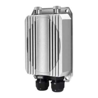
Overview CERIO’s OW-300N2-A2 eXtreme Power 11n 2.4GHz 2x2 +10dBi + Heater Outdoor Bridge/Access Point (1000mW) utilizes a built-in CenOS 3.0 software core and is compatible with CERIO Wireless Management Software. Our CenOS 3.0 software core and CWMS management software promotes operation efficiency and network management, making them very suitable for outdoor wireless deployment. - Page 6 WISPs deliver wireless broadband Internet service to new residential and business customers. In this mode, OW-300N2-A2 is enabled with DHCP Server functions. The wired clients of OW-300N2-A2 are in the same subnet from Main Base Station and it accepts wireless connections from client devices WISP +AP Mode ...
-
Page 7: Features
In the CPE mode, OW-300N2-A2 is a gateway enabled with NAT and DHCP Server functions. The wired clients connected to OW-300N2-A2 are in different subnet from those connected to Main Base Station, and, in CPE mode, it does not accept wireless association from wireless clients. - Page 8 Wireless Feature Transmission power control : 1~100% Channel selection : Manual or Auto No of associated clients per AP : 32 Setting for max no associated clients : Yes Supports 8 virtual ESSID and associated clients per AP to 32 and the Pure WDS Max. 4 ...
-
Page 9: Ap Mode Configuration
Web-based GUI interface. 2.1 Choose Your Operating Mode ( AP Mode ) OW-300N2-A2 Operating mode supports five operation modes: Router AP mode, AP mode, WDS mode, CPE mode and Client Bridge + Repeater AP mode, respectively with built-in remote management features. -
Page 10: External Network Connection
2.2 External Network Connection Network Requirement Normally, OW-300N2-A2 connects to a wired LAN and provides a wireless connection point to associate with wireless client. Then, Wireless clients could access to LAN or Internet by associating themselves with OW-300N2-A2 set in AP mode. - Page 11 Static IP: The administrator can manually setup the LAN IP address when static IP is available/ preferred. IP Address : The IP address of the LAN port; default IP address is 192.168.2.254 IP Netmask : The Subnet mask of the LAN port; default Netmask is 255.255.255.0 ...
-
Page 12: Wireless General Setup
Band Mode : Select an appropriate wireless band; bands available are 801.11 b/g/n mixed mode Country : a region, the OW-300N2-A2 support region for US,ETSI and Japan Channel : Choosing the best WiFi channel Auto Scan : Smart channel judgment, the function can auto choose use best Channel ... - Page 13 HT TxStream/RxStream : By default, it's 2 Channel Bandwidth : The "20/40” MHz option is usually best. The other option is available for special circumstances. Extension Channel : Only for Channel Bandwidth “40” MHz. Select the desired channel bonding for control.
-
Page 14: Configure Wireless Advanced Setup
2.5 Configure Wireless Advanced Setup The administrator can change the Slot Time, ACK Timeout, RTS threshold and fragmentation threshold settings for the system. Please click on Wireless -> Advanced Setup and follow the below setting. Slot Time : Slot time is in the range of 9~1489 and set in unit of microsecond. The default value is 9 microsecond. - Page 15 collision because of hidden wireless clients or other causes. When collision sources can be removed sooner and other senders attempting to send are listening the channel(CSMA/CA) the owner of the channel should continue ownership and finish their transmission and release the channel. Then, following ownership of the channel will be sooner for the new pair due to shorter slot time.
- Page 16 overhead, but that will likely delay the association and roaming process because stations scanning for available access points may miss the beacons. You can decrease the beacon interval, which increases the rate of beacons. This will make the association and roaming process very responsive;...
- Page 17 Greenfield : In wireless WLAN technology, greenfield mode is a feature of major components of the 802.11n specification. The greenfield mode feature is designed to improve efficiency by eliminating support for 802.11b/g devices in an all draft-n network. In greenfield mode the network can be set to ignore all earlier standards. ...
- Page 18 AC_BE Best Effort Medium Medium throughput and delay. Most traditional IP data is sent to this queue. AC_VI Video High Minimum delay. Time-sensitive video data is automatically sent to this queue. AC_VO Voice High Time-sensitive data like VoIP and streaming media are automatically sent to this queue.
-
Page 19: Create Virtual Ap - Virtual Ap Setup
Antenna: OW-300N2-A2 utilizes 2 built-In 10dBi Directional antenna and also supports 2 N-type antenna connections. Administrator can enter the software UI and select either built-in directional antennas or N-Type external antenna. Internal and external antennas cannot be used simultaneously. - Page 20 VAP: Display number of system's Virtual AP. MAC Address: The MAC address of the VAP Interface is displayed here. When you enable AP and reboot system, the MAC address will display here ESSID: Display Virtual AP's ESSID; default is AP00~AP07. ...
- Page 21 ESSID: Extended Service Set ID indicates the SSID which the clients used to connect to the VAP. ESSID will determine the service type of a client which is assigned to the specified VAP. Hidden SSID: Select this option to enable the SSID to broadcast in your network. When configuring the network, it is suggested to enable this function but disable it when the configuration is complete.
- Page 22 Client Isolation: Select Enable, all clients will be isolated from each other. That mean all clients cannot reach to other clients. IAPP: Inter Access-Point Protocol is designed for the enforcement of unique association throughout a ESS(Extended Service Set) and for secure exchange of station's security context between current access point (AP) and new AP during hand off period.
- Page 23 Key Index: You can select the Key which you want to use. Other wireless station must have the same key value to connect with OW-300N2-A2, 4 different WEP keys can be configured at the same time, but only one is used. Effective key is set with a choice of WEP Key 1, 2, 3 or 4.
- Page 24 Key Type: Check on the respected button to enable either ASCII or HEX format for the Pre-shared Key. Pre-Shared Key: Enter the information for pre-shared key; the format of the information shall according to the key type selected. Pre-shared key can be either entered as a 256-bit secret in 64 HEX digits format, or 8 to 63 ASCII characters.
- Page 25 Master Key Update Period: This time interval for re-keying GMK (master key used internally to generate GTKs) in seconds. Enter the time-length required; the default time is 83400 seconds. EAP Reauth Period: This time interval for re- authentication in seconds. Enter the time-length required;...
- Page 26 Dynamic WEP Settings WEP Key length: Check on the respected button to enable either 64bits or 128bits key length. The system will automatically generate WEP keys for encryption. WEP Key Update Period: The time interval WEP will then be updated; the unit is in seconds;...
- Page 27 Shared secret: The secret key for system to communicate with Authentication RADIUS server. Support 1 to 64 characters. VAP MAC Filter Setup In this function, the administrator can allow or reject clients to access the Virtual AP. Please click on Wireless ->...
-
Page 28: Wds Setup - Expand Your Wireless Network
“WDS” function in AP Mode both Wireless and Ethernet user can connect your local network at the same time through OW-300N2-A2. Please click on Wireless -> Virtual AP Setup, click “Edit” of Virtual AP List and follow the below setting. -
Page 29: Associated Clients
2.10 Associated Clients The administrator can obtain detailed wireless information and all associated clients status via this page. Please click on Wireless -> Associated Clients. The the Associated Clients Status appears. Wireless Information: Display the Virtual AP configuration information of the system. ... -
Page 30: Wds Mode Configuration
3.2 External Network Connection ( Network Requirement ) You could expand your Ethernet network via WDS link. In this mode, the OW-300N2-A2 connects directly to a wired LAN, and wirelessly bridges to a remote access point via a WDS link as shown in picture. - Page 31 IP Gateway : The default gateway of the LAN port Dynamic IP: This configuration type is applicable when the OW-300N2-A2 is connected to a network with the presence of a DHCP server; all related IP information will be provided by the DHCP server automatically.
-
Page 32: Wireless General Settings
DNS: Check either “No Default DNS Server” or “Specify DNS Server IP” button as desired to set up the system DNS. Primary : The IP address of the primary DNS server. Secondary : The IP address of the secondary DNS server. ... - Page 33 MAC Address : The MAC address of the Wireless interface is displayed here. Band Mode : Select an appropriate wireless band; bands available are 801.11 b/g/n mixed mode Country : a region, the OW-300N2-A2support region for US,ETSI and Japan ...
- Page 34 HT TxStream/RxStream : By default, it's 2 Channel Bandwidth : The "20/40” MHz option is usually best. The other option is available for special circumstances. Extension Channel : Only for Channel Bandwidth “40” MHz. Select the desired channel bonding for control.
-
Page 35: Configure Wireless Advanced Setup
Configure Wireless Advanced Setup The administrator can change the Slot Time, ACK Timeout, RTS threshold and fragmentation threshold settings for the system. Please click on Wireless -> Advanced Setup and follow the below setting. Slot Time : Slot time is in the range of 9~1489 and set in unit of microsecond. The default value is 9 microsecond. - Page 36 ACK Timeout is adjustable due to the fact that distance between two radio links may vary in different deployment. ACK Timeout makes significant influence in performance of long distance radio link. If ACK Timeout is set too short, transmitter will start to “Resend” packet before ACK is received, and throughput become low due to excessively high re-transmission.
- Page 37 RTS Threshold : TRTS Threshold is in the range of 1~2347 byte. The default is 2347 byte. The main purpose of enabling RTS by changing RTS threshold is to reduce possible collisions due to hidden wireless clients. RTS in AP will be enabled automatically if the packet size is larger than the Threshold value.
- Page 38 AC Type: Data Queue Transmitted Priority Description AP to Clients AC_BK Background High throughput. Bulk data that requires maximum throughput and is not time-sensitive is sent to this queue (FTP data, for example). AC_BE Best Effort Medium Medium throughput and delay. Most traditional IP data is sent to this queue.
- Page 39 Contention Window is the upper limit (in milliseconds) for the doubling of the random backoff value. This doubling continues until either the data frame is sent or the Maximum Contention Window size is reached. Once the Maximum Contention Window size is reached, retries will continue until a maximum number of retries allowed is reached.
-
Page 40: Wds Setup
Antenna: OW-300N2-A2 utilizes 2 built-In 10dBi Directional antenna and also supports 2 N-type antenna connections. Administrator can enter the software UI and select either built-in directional antennas or N-Type external antenna. Internal and external antennas cannot be used simultaneously. By default, OW-300N2-A2 is set to built-in directional antennas. -
Page 41: Wds Status
WDS MAC List Enable : Check “Enable” to create WDS link. WDS Peer's MAC Address : Enter the MAC address of WDS peer. VLAN Tag(ID): Virtual LAN, the system supports tagged VLAN with WDS. To enable VLAN function;... -
Page 42: Choose Your Operating Mode(Client Bridge + Repeater Ap)
WISPs deliver wireless broadband Internet service to new residential and business customers. In this mode, OW-300N2-A2 is enabled with DHCP Server functions. The wired clients of OW-300N2-A2 are in the same subnet from Main Base Station and it accepts wireless connections from client devices. - Page 43 LAN IP Setup : The administrator can manually setup the LAN IP address. IP Address : The IP address of the LAN port; default IP address is 192.168.2.254 IP Netmask : The Subnet mask of the LAN port; default Netmask is 255.255.255.0 ...
- Page 44 DHCP Setup : Devices connected to the system can obtain an IP address automatically when this service is enabled. DHCP : Check Enable button to activate this function or Disable to deactivate this service. Start IP / End IP: Specify the range of IP addresses to be used by the DHCP server when assigning IP address to clients.
-
Page 45: Wireless General Setup
Band Mode : Select an appropriate wireless band; bands available are 801.11 b/g/n mixed mode Country : a region, the OW-300N2-A2 support region for US,ETSI and Japan TX Power : You can adjust the output power of the system to get the appropriate coverage for your wireless network. -
Page 46: Configure Wireless Advanced Setup
transmission rate will be selected. You have the option of selecting the speed if necessary. Shout GI : Short Guard Interval, by default, it's “Enable”. it's can increase throughput. However, it can also increase error rate in some installations, due to increased sensitivity to radio-frequency reflections. - Page 47 station waits before sending a packet on the LAN. For a sender and receiver own right of the channel the shorter slot time help manage shorter wait time to re-transmit from collision because of hidden wireless clients or other causes. When collision sources can be removed sooner and other senders attempting to send are listening the channel(CSMA/CA) the owner of the channel should continue ownership and finish their transmission and release the channel.
- Page 48 By increasing the beacon interval, you can reduce the number of beacons and associated overhead, but that will likely delay the association and roaming process because stations scanning for available access points may miss the beacons. You can decrease the beacon interval, which increases the rate of beacons.
- Page 49 links which do not need them and thus controls which ports receive specific multicast traffic. Greenfield : In wireless WLAN technology, greenfield mode is a feature of major components of the 802.11n specification. The greenfield mode feature is designed to improve efficiency by eliminating support for 802.11b/g devices in an all draft-n network.
- Page 50 maximum throughput and is not time-sensitive is sent to this queue (FTP data, for example). AC_BE Best Effort Medium Medium throughput and delay. Most traditional IP data is sent to this queue. AC_VI Video High Minimum delay. Time-sensitive video data is automatically sent to this queue.
-
Page 51: Site Survey
Antenna: OW-300N2-A2 utilizes 2 built-In 10dBi Directional antenna and also supports 2 N-type antenna connections. Administrator can enter the software UI and select either built-in directional antennas or N-Type external antenna. Internal and external antennas cannot be used simultaneously. -
Page 52: Station Profile
ESSID: Available Extend Service Set ID of surrounding Access Points. MAC Address: MAC addresses of surrounding Access Points. Signal/Noise dBm: Received signal strength of all found Access Points. RSSI: Indicate the RSSI of the respective client's association. ... - Page 53 Lock to AP MAC: the function will lock remote AP MAC Address. Security Type : Select an appropriate security type for association, the Security Type can be selected in “NONE”, “OPEN”, “SHARED”, “WPA-PSK”, or “WPA2-PSK” from drop-down list; the type needs to be the same as that associated access point. ...
-
Page 54: Remote Ap Status
Before you click “Connect” button for connection, Please double check the “Channel” setting of “Wireless General Setup” page on OW-300N2-A2 as it must be the same with associated AP channel setting If you only click “Connect” button and does not click “Save” button. The selected profile would not be saved on the Profile List Change these settings as described here and click Save button to save your changes. - Page 55 security type settings and MAC Filter settings. ESSID : Extended Service Set ID, When clients are browsing for available wireless networks, this is the SSID that will appear in the list. ESSID will determine the service type available to AP clients associated with the specified VAP.
- Page 56 Key Index : Skey index is used to designate the WEP key during data transmission. 4 different WEP keys can be entered at the same time, but only one is chosen. Key Auth Method : Enable the desire option among OPEN or SHARED . ...
- Page 57 WPA-Enterprise (or WPA2-Enterprise): The RADIUS authentication and encryption will be both enabled if this is selected. WPA General Settings : Cipher Suite : By default, it is AES. Select either AES or TKIP cipher suites. Group Key Update Period : By default, it’s 3600 seconds. This time interval for rekeying GTK, broadcast/multicast encryption keys, in seconds.
-
Page 58: Repeater Ap Mac Filter Setup
server. Shared secret : A secret key used between system and RADIUS server. Supports 8 to 64 characters. Session Timeout : The Session timeout is in the range of 0~60 seconds. The default is 0 to disable re-authenticate service. Amount of time before a client will be required to re-authenticate. -
Page 59: Router Ap Mode Configuration
reject clients to access each Virtual AP. Action: Select the desired access control type from the drop-down list; the options are Disable, Allow or Reject. Only Allow List MAC: Define certain wireless clients in the list which will have granted access to the Access Point while the access will be denied for all the remaining clients –... -
Page 60: Choose Your Operating Mode ( Router Ap Mode )
5.2 External Network Connection Network Requirement It can be used as an Router AP with WDS function. In this mode, CERIO OW-300N2-A2 is a gateway enabled with NAT and DHCP Server functions. The wireless clients connected to Internet. ... - Page 61 Mode : By default, it’s “Static IP”. Check “Static IP”, “Dynamic IP”, “PPPoE” or “PPTP”to set up system WAN IP Static IP : Users can manually setup the WAN IP address with a static IP provided by WISP. ...
- Page 62 Hostname : The Hostname of the WAN port PPPoE : To create wireless PPPoE WAN connection to a PPPoE server in network. User Name : Enter User Name for PPPoE connection Password : Enter Password for PPPoE connection ...
- Page 63 IP Address : The IP address of the WAN port IP Netmask : The Subnet mask of the WAN port PPTP Server IP Address : The IP address of the PPTP server User Name : Enter User Name for PPTP connection ...
- Page 64 DNS : Check “No Default DNS Server” or “Specify DNS Server IP” radial button as desired to set up system DNS. Primary : The IP address of the primary DNS server. Secondary : The IP address of the secondary DNS server. ...
-
Page 65: Configure Ddns Setup
User Name & Password: User Name and Password are used to login DDNS service. Click “Save” button to save your changes. Click Reboot button to activate your changes 5.4 Configure OW-300N2-A2 LAN IP Address Here are the instructions for how to setup the local IP Address and Netmask. Please click on System ->... - Page 66 IP Netmask : The Subnet mask of the LAN port; default Netmask is 255.255.255.0 802.1d Spanning Tree : The spanning tree network protocol provides a loop free topology for a bridged LAN between LAN interface and 8 WDS interfaces from wds0 to wds7. The Spanning Tree Protocol, which is also referred to as STP, is defined in the IEEE Standard 802.1d.
-
Page 67: Wireless General Setup
Band Mode : Select an appropriate wireless band; bands available are 801.11 b/g/n mixed mode Country : a region, the OW-300N2-A2 support region for US,ETSI and Japan Channel : Choosing the best WiFi channel Auto Scan : Smart channel judgment, the function can auto choose use best Channel ... - Page 68 TX Power : You can adjust the output power of the system to get the appropriate coverage for your wireless network. Specify digit numbers between level 1 to level 9 (the unit is %) for your environment. If you are not sure which setting to choose, then keep the default setting level 9 (100%).
-
Page 69: Configure Wireless Advanced Setup
Change these settings as described here and click Save button to save your changes. Click Reboot button to activate your changes. The items in this page is for AP's RF general settings and will be applied to all VAPs and WDS Link. 5.6 Configure Wireless Advanced Setup The administrator can change the Slot Time, ACK Timeout, RTS threshold and fragmentation threshold settings for the system. - Page 70 ACK Timeout : ACK timeout is in the range of 1~372 and set in unit of microsecond. The default value is 64 microsecond. All data transmission in 802.11b/g request an “Acknowledgement” (ACK) send by receiving radio. The transmitter will resend the original packet if correspondent ACK failed to arrive within specific time interval, also refer to as “ACK Timeout”.
- Page 71 DTIM Interval : The DTIM interval is in the range of 1~255. The default is 1. DTIM is defined as Delivery Traffic Indication Message. It is used to notify the wireless stations, which support power saving mode, when to wake up to receive multicast frame. DTIM is necessary and critical in wireless environment as a mechanism to fulfill power-saving synchronization.
- Page 72 WMM QoS : This affects traffic flowing from the access point to the client station. Configuring QoS options consists of setting parameters on existing queues for different types of wireless traffic. You can configure different minimum and maximum wait times for the transmission of packets in each queue based on the requirements of the media being sent.
- Page 73 are automatically sent to this queue. CWmin:Minimum Contention Window. This parameter is input to the algorithm that determines the initial random backoff wait time ("window") for retry of a transmission. The value specified here in the Minimum Contention Window is the upper limit (in milliseconds) of a range from which the initial random backoff wait time is determined.。...
-
Page 74: Create Virtual Ap - Virtual Ap Setup
When the Normal ACK policy is used, the recipient acknowledges each received uncast packet.。 Antenna: OW-300N2-A2 utilizes 2 built-In 10dBi Directional antenna and also supports 2 N-type antenna connections. Administrator can enter the software UI and select either built-in directional antennas or N-Type external antenna. Internal and external antennas cannot be used simultaneously. -
Page 75: Virtual Ap General Configuration
Change these settings as described here and click Save button to save your changes. Click Reboot button to activate your changes 5.8 Virtual AP General Configuration For each Virtual AP, administrators can configure general settings and security type. Click Wireless -> Virtual AP Setup, click “Edit” of Virtual AP List and then Virtual AP Configuration page appears. - Page 76 ESSID: Extended Service Set ID indicates the SSID which the clients used to connect to the VAP. ESSID will determine the service type of a client which is assigned to the specified VAP. Hidden SSID: Select this option to enable the SSID to broadcast in your network. When configuring the network, it is suggested to enable this function but disable it when the configuration is complete.
- Page 77 Key Index: You can select the Key which you want to use. Other wireless station must have the same key value to connect with OW-300N2-A2, 4 different WEP keys can be configured at the same time, but only one is used. Effective key is set with a choice of WEP Key 1, 2, 3 or 4.
- Page 78 encryption strength can use 32 digits for HEX (0~9, a~f and A-F) or 16 digits for ASCII (0~9, a~z and A~Z) WPA-PSK (or WPA2-PSK): WPA-PSK is short for W-Fi Protected Access-Pre-Shared Key. WPA-SPK uses the same encryption way with WPA, and the only difference between them is that WPA-PSK recreates a simple shared key, instead of using the user’s certification.
- Page 79 General Setting: Cipher Suite: You can chose use AES or TKIP with your WPA / WPA2 encryption method, AES is short for “Advanced Encryption Standard”, The AES cipher is specified as a number of repetitions of transformation rounds that convert the input plaintext into the final output of ciphertext.
- Page 80 Authentication RADIUS Server Settings Authentication Server: Enter the IP address of the Authentication RADIUS server. Port: The port number used by Authentication RADIUS server. Use the default 1812 or enter port number specified. Shared secret: The secret key for system to communicate with Authentication RADIUS server.
- Page 81 Dynamic WEP Settings WEP Key length: Check on the respected button to enable either 64bits or 128bits key length. The system will automatically generate WEP keys for encryption. WEP Key Update Period: The time interval WEP will then be updated; the unit is in seconds;...
- Page 82 Shared secret: The secret key for system to communicate with Authentication RADIUS server. Support 1 to 64 characters. VAP MAC Filter Setup In this function, the administrator can allow or reject clients to access the Virtual AP. Please click on Wireless ->...
-
Page 83: Wds Setup - Expand Your Wireless Network
5.9 WDS Setup - Expand your Wireless Network Service: By default, it's “Disable”. To “Enable” to activate WDS Enable: Click Enable checkbox to create WDS link. WDS Peer's MAC Address: Enter the MAC address of WDS peer. ... -
Page 84: Associated Clients
5.11 Associated Clients The administrator can obtain detailed wireless information and all associated clients status via this page. Please click on Wireless -> Associated Clients. The Associated Clients Status appears. Wireless Information : Display the Virtual AP configuration information of the system. ... -
Page 85: External Network Connection ( Network Requirement )
In WISP mode, the WAN port is the Wireless interface. 6.3 Configure CPE(WAN) Setup It can be used as an Router AP with WDS function. In this mode, OW-300N2-A2 is a gateway enabled with NAT and DHCP Server functions. The wireless clients connected to Internet. - Page 86 Mode : By default, it’s “Static IP”. Check “Static IP”, “Dynamic IP”, “PPPoE” or “PPTP”to set up system WAN IP Static IP : Users can manually setup the WAN IP address with a static IP provided by WISP. ...
- Page 87 Hostname : The Hostname of the WAN port PPPoE : To create wireless PPPoE WAN connection to a PPPoE server in network. User Name : Enter User Name for PPPoE connection Password : Enter Password for PPPoE connection ...
- Page 88 PPTP : The Point-to-Point Tunneling Protocol (PPTP) mode enables the implementation of secure multi-protocol Virtual Private Networks (VPNs) through public networks. IP Address : The IP address of the WAN port IP Netmask : The Subnet mask of the WAN port ...
- Page 89 MTU : By default, it’s 1460 bytes. MTU stands for Maximum Transmission Unit. Consult with WISP for a correct MTU setting. MPPE Encryption : Microsoft Point-to-Point Encryption (MPPE) encrypts data in Point-to-Point Protocol(PPP)-based dial-up connections or Point-to-Point Tunneling Protocol (PPTP) virtual private network (VPN) connections.
-
Page 90: Configure Ow-300N2-A2 Lan Ip Address
Manual MAC Address : Enter the MAC address registered with your ISP. Click Save button to save your changes. Click Reboot button to activate your changes 6.4 Configure OW-300N2-A2 LAN IP Address Here are the instructions for how to setup the local IP Address and Netmask. Please click on System ->... - Page 91 DHCP Setup : Devices connected to the system can obtain an IP address automatically when this service is enabled. DHCP : Check Enable button to activate this function or Disable to deactivate this service. Start IP / End IP: Specify the range of IP addresses to be used by the DHCP server when assigning IP address to clients.
-
Page 92: Configure Ddns Setup
Click Save button to save your changes. Click Reboot button to activate your changes 6.5 Configure DDNS Setup Dynamic DNS allows you to map domain name to dynamic IP address. Please click on System -> DDNS Setup and follow the below setting. ... - Page 93 Band Mode : Select an appropriate wireless band; bands available are 801.11 b/g/n mixed mode Country : a region, the OW-300N2-A2 support region for US,ETSI and Japan TX Power : You can adjust the output power of the system to get the appropriate coverage for your wireless network.
-
Page 94: Configure Wireless Advanced Setup
Aggregation : By default, it's “Enable”. Select “Disable” to deactivate Aggregation. A part of the 802.11n standard (or draft-standard). It allows sending multiple frames per single access to the medium by combining frames together into one larger frame. It creates the larger frame by combining smaller frames with the same physical source and destination end points and traffic class (i.e. - Page 95 For a sender and receiver own right of the channel the shorter slot time help manage shorter wait time to re-transmit from collision because of hidden wireless clients or other causes. When collision sources can be removed sooner and other senders attempting to send are listening the channel(CSMA/CA) the owner of the channel should continue ownership and finish their transmission and release the channel.
- Page 96 All the radio stations received beacon recognizes the existence of such AP, and may proceed next actions if the information from AP matches the requirement. Beacon is sent on a periodic basis, the time interval can be adjusted. By increasing the beacon interval, you can reduce the number of beacons and associated overhead, but that will likely delay the association and roaming process because stations scanning for available access points may miss the beacons.
- Page 97 IGMP Snooping : the process of listening to Internet Group Management Protocol (IGMP) network traffic. The feature allows a network switch to listen in on the IGMP conversation between hosts and routers. By listening to these conversations the switch maintains a map of which links need which IP multicast streams.
- Page 98 AC Type: Queue AP to Clients Priority Description AC_BK Background High throughput. Bulk data that requires maximum throughput and is not time-sensitive is sent to this queue (FTP data, for example). AC_BE Best Effort Medium Medium throughput and delay. Most traditional IP data is sent to this queue.
-
Page 99: Site Survey
Antenna: OW-300N2-A2 utilizes 2 built-In 10dBi Directional antenna and also supports 2 N-type antenna connections. Administrator can enter the software UI and select either built-in directional antennas or N-Type external antenna. Internal and external antennas cannot be used simultaneously. -
Page 100: Station Profile
ESSID : Available Extend Service Set ID of surrounding Access Points. MAC Address : MAC addresses of surrounding Access Points. Signal/Noise dBm : Received signal strength of all found Access Points. RSSI : Indicate the RSSI of the respective client's association. ... - Page 101 Connection Setup : Can you choose Fix or cycle General Configuration : MAC address : The remote AP MAC Address Profile Name : Set different profiles for quick connection uses. ESSID : Assign Service Set ID for the wireless system. ...
- Page 102 Key Index : key index is used to designate the WEP key during data transmission. 4 different WEP keys can be entered at the same time, but only one is chosen. WEP Key # : Enter HEX or ASCII format WEP key value; the system supports up to 4 sets of WEP keys.
-
Page 103: Remote Ap Status
If you only click “Connect” button and does not click “Save” button. The selected profile would not be saved on the Profile List Change these settings as described here and click Save button to save your changes. Click Reboot button to activate your changes. 6.10 Remote AP Status Show the remote bridge AP whether is link or unlinked 6.11... - Page 104 your network. When disabled, people could easily obtain the SSID information with the site survey software and get access to the network if security is not turned on. When enabled, network security is enhanced. It’s suggested to enable it after AP security settings are archived and setting of AP clients could make to associate to it.
- Page 105 Key Length ASCII 64-bit 10 characters 5 characters 128-bit 26 characters 13 characters WPA-PSK (or WPA2-PSK) : WPA (or WPA2) Algorithms, allows the system accessing the network by using the WPA-PSK protected access. Cipher Suite : By default, it is AES. Select either AES or TKIP cipher suites. ...
- Page 106 WPA General Settings : Cipher Suite : By default, it is AES. Select either AES or TKIP cipher suites. Group Key Update Period : By default, it’s 3600 seconds. This time interval for rekeying GTK, broadcast/multicast encryption keys, in seconds. Entering the time-length is required.
-
Page 107: Repeater Ap Mac Filter Setup
required to re-authenticate. WEP 802.1X : When WEP 802.1x Authentication is enabled, please refer to the following Dynamic WEP and RADIUS settings to complete configuration. Authentication Radius Server Settings : IP Address : Enter the IP address of the Authentication RADIUS server. ... -
Page 108: System Management
Continue Virtual AP Setup section. For each Virtual AP setting, the administrator can allow or reject clients to access each Virtual AP. Action: Select the desired access control type from the drop-down list; the options are Disable, Allow or Reject. ... -
Page 109: Configure Management
7.1 Configure Management Administrator could specify geographical location of the system via instructions in this page. Administrator could also enter new Root and Admin passwords and allow multiple login methods. Please click System -> Management and follow the below settings ... - Page 110 RSA key. Ping Watchdog : The ping watchdog sets the OW-300N2-A2 Device to continuously ping a user defined IP address (it can be the internet gateway for example). If it is unable to ping under the user defined constraints, the OW-300N2-A2 device will automatically reboot.
-
Page 111: Configure System Time
seconds as the network interface and wireless connection initialization takes considerable amount of time if the device is rebooted. Default is 300 seconds. Failure Count To Reboot : specify the number of ICMP “echo response” replies. If the specified number of ICMP “echo response” packets is not received continuously, the Ping Watchdog Tool will reboot the device. -
Page 112: Configure Upnp Setup
Please click on System -> Time Server and follow the below setting. Local Time : Display the current system time. Setup Time Use NTP : To synchronize the system time with NTP server. Default NTP Server / NTP Server : Select the NTP Server from the drop-down list. ... -
Page 113: Configure Snmp Setup
UPnP : By default, it’s “Disable”. Select “Disable” or “Enable” of UPnP Service. For UPnP to work in Windows OS, the “OW-300N2-A2” must be available in “Network Places”, as shown here: (your specific model may vary) If these devices are not available, you should verify that the correct components and services are loaded in Windows OS. - Page 114 SNMP managers and agents. By enabling SNMP function, the administrator can obtain the system information remotely. Please click on System -> SNMP and follow the below setting. SNMP v2c Enable: Check to enable SNMP v2c. ro community : Set a community string to authorize read-only access. ...
-
Page 115: Configure Advance Setup
SNMP Trap : Events such as cold start, interface up & down, and association & disassociation will report to an assigned server. Community : Set a community string required by the remote host computer that will receive trap messages or notices send by the system. ... -
Page 116: Ip Filter
is supported. Static Assignment : Enter external and internal IP address of DMZ host. The function only external IP to Internal IP address Click Save button to save your changes. Click Reboot button to activate your changes. 8.2 IP Filter Allows to create deny or allow rules to filter ingress or egress packets from specific source and/or to destination IP address on wired (LAN) or Wireless (WAN) ports. - Page 117 Source Address/Mask : Enter desired source IP address and netmask. i.e. 192.168.2.10/32. Source Port : Enter a port or a range of ports as start:end. i.e. port 20:80 Destination Address/Mask : Enter desired destination IP address and netmask. i.e. 192.168.1.10/32 ...
-
Page 118: Mac Filter
Example 1 : Create a higher priority rule to allow IP address 192.168.2.2 Telnet access from LAN port first, and deny Telnet access from remaining IP addresses in the same subnet. Source Destination Rule In/Out Protocol Listen Action Side IP/Mask Port IP/Mask Port... -
Page 119: Virtual Server
MAC Address : Enter MAC address (e.g. aa:bb:cc:00:00:0a) and click “Add” button, then the MAC address should display in the MAC Filter List. There are a maximum of 20 clients allowed in this MAC Filter List. The MAC addresses of the wireless clients can be added and removed to the list using the Add and Delete buttons. - Page 120 Service : By Default, It’s “Disable”. Check Enable radial button to enable Virtual Server. Description : Enter appropriate message for resource sharing via Virtual Server. Private IP : Enter corresponding IP address of internal resource to share. ...
-
Page 121: Parental Control
DMZ Enabled : 192.168.2.12 Rule Protocol Private IP Private Port Public Port 192.168.2.11 20:80 20:80 192.168.2.10 8.5 Parental Control Parental Control allows you to block or allow specific kinds of Internet usage and traffic, such as Internet access, designated services, and websites. Please click on Advance ->... - Page 122 Local / Destination IP : Specify local(LAN)/ destination IP addresses range required for this rule. If you specify local IP addresses range from 192.168.1.1 to 192.168.2.254. The matches a range of local IP addresses include every single IP address from the first to the last, so the example above includes everything from 192.168.1.1 to 192.168.2.254.
-
Page 123: Qos
8.6 QoS Quality of Service (QoS) refers to both a network's ability to deliver data with minimum delay, and the networking methods used to control the use of bandwidth. Without QoS, all traffic data is equally likely to be dropped when the network is congested. This can cause a reduction in network performance and make the network inadequate for time-critical application such as video-on-demand. -
Page 124: Ip Routing
Comment : Enter a descriptive name for this rule for identifying purposes. IP Address / IP segment : Specify local(LAN)/ destination IP addresses range required for this rule. If you specify local IP addresses range from 192.168.1.1 to 192.168.1.254. The matches a range of local IP addresses include every single IP address from the first to the last, so the example above includes everything from 192.168.1.1 to 192.168.1.254. - Page 125 OSPF Service : By default, it's Disable. To Enable to activated OSPF routing service. Route ID : The router ID is typically derived by each router from its interface IP address. Distribute RIP over OSPF : Allow RIP routes will redistributed into OSPF. RIP Settings : ...
-
Page 126: Time Policy
Gateway : Enter gateway IP address Interface : Choose the interface via LAN or WAN Protocol : Set static routing rule to RIP or OSPF network. Select RIP to associate specific network on RIP routing process. Select OSPF to associate specific network with the specified area on OSPF routing process Click “Save”... -
Page 127: Configure Utilities Setup
Policy : There are 10 Policy can be selected. Schedule Rule : Select desired schedule for this policy. Time Schedule : Select desired day of week and time period for this policy. Below depicts an example for “On Schedule”... -
Page 128: Firmware Upgrade
Save Settings to PC : Click Save button to save the current configuration to a local disk. Load Settings from PC : Click Browse button to locate a configuration file to restore, and then click Upload button to upload. ... - Page 129 2. Do not interrupt during firmware upgrade including power on/off as this may damage system. Firmware Information Show currently the OW-300N2-A2 of system software version and software date Upgrade firmware The upgrade firmware will support via local PC and TFTP Server and HTTP URL to upgrade...
-
Page 130: Network Utility
Traceroute : Allows tracing the hops from the OW-300N2-A2 device to a selected outgoing IP address. It should be used for the finding the route taken by ICMP packets across the network to the destination host. The test is started using the Start button, click Stop button to stopped test. -
Page 131: Reboot
Service : PoE Bridge function is “Disabled” by default. 9.5 Reboot This function allows user to restart system with existing or most current settings when changes are made. Click Reboot button to proceed and take around three minutes to complete. The System Overview page appears upon the completion of reboot. -
Page 132: Configure Status
10. Configure Status 10.1 Overview Detailed information on System, Network can be reviewed via this page. System Information : Display the information of the system. Device Information : Display the information of the Port link. CPU Information : Display the information of the system CPU ... -
Page 133: Extra Info
Route Information : Select “Route Information” on the drop-down list to display route table. OW-300N2-A2 could be used as a L2 or L3 device. It doesn’t support dynamic routing protocols such as RIP or OSPF. Static routes to specific hosts, networks or default gateway are set up automatically according to the IP configuration of system's interfaces. - Page 134 ARP Table Information : Select “ARP Table Information” on the drop-down list to display ARP table. ARP associates each IP address to a unique hardware address (MAC) of a device. It is important to have a unique IP address as final destination to switch packets to. ...
-
Page 135: Event Log
This table displays local MAC addresses associated with wired or wireless interfaces, but also remember non-local MAC addresses learned from wired or wireless interfaces. Ageing timers will be reset when existing MAC addresses in table are learned again or added when new MAC addresses are seen from wired or wireless interfaces as well. - Page 136 Time : The date and time when the event occurred. Facility : It helps users to identify source of events such “System” or “User” Severity : Severity level that a specific event is associated such as “info”, “error”, “warning”, etc.
-
Page 137: Appendix A. Windows Tcp/Ip Settings
Appendix A. Windows TCP/IP Settings Windows XP Click Start -> Settings -> Control Panel, and then “Control Panel” window appears. Click on “Network Connections”, and then “Network Connections” window appears. Click right on “Local Area Connection”, and select Properties. - Page 138 iii. In “Local Area Connection Properties” window, select “Internet Protocol (TCP/IP)” and click on Properties button. iv. Select “Use the following IP address”, and type in IP address : 192.168.2.100 Subnet mask : 255.255.255.0 Click “OK” completion set up IP address...
-
Page 139: Appendix B. Web Gui Valid Characters
Appendix B. WEB GUI Valid Characters Table B WEB GUI Valid Characters Block Field Valid Characters IP Address IP Format; 1-254 IP Netmask 128.0.0.0 ~ 255.255.255.252 IP Gateway IP Format; 1-254 Primary DNS IP Format; 1-254 Secondary DNS IP Format; 1-254 Hostname Length : 32 0-9, A-Z, a-z... - Page 140 Domain Length : 32 0-9, A-Z, a-z ~ ! @ # $ % ^ * ( ) _ + - { } | : < > ? [ ] / ; ` , . = Lease Time 600 ~ 99999999 Table B WEB GUI Valid Characters (continued) Block...
- Page 141 Table B WEB GUI Valid Characters (continued) Block Field Valid Characters Virtual AP Setup ESSID Length : 31 Space 0-9, A-Z, a-z ~ ! @ # $ % ^ * ( ) _ + - { } | : < > ? [ ] / ; ` , . = Maximum Clients 1 ~ 32 VLAN ID...
- Page 142 Block Field Valid Characters Local/ Destination IP IP Formate; 1-254 Local/ Destination Port 1 ~ 65535 Upload & Download 8 ~ 8192 digital number...
-
Page 143: Appendix C. Mcs Data Rate
Appendix C. MCS Data Rate The table below shows the relationships between the variables that allow for the maximum data rate Table C MCS Data Rate Data Rate (Mb/s) Channel Bandwidth = 20 Channel Bandwidth = 40 MCS Index Modulation Long Guard Short Guard Long Guard... -
Page 144: Appendix D. Enabling Upnp In Windows Xp
Appendix D. Enabling UPnP in Windows Open the “Add/Remove Programs” control panel, and then click on “Add/Remove Windows Components” in the sidebar. Scroll down and find “Networking Services”, highlight it, and then click Details. In the “Networking Services” window, ensure that the “Internet Gateway Device” and “UPnP User Interface”... - Page 145 iii. Next, in the “Control panel”, open the “Administrative Tools” and then open “Services”. Scroll down until you find the “SSDP Discovery Interface”. If the Status is not Started, double-click on SSDP Discovery Interface to open the service properties. Change the startup type to Automatic, then close the properties.
-
Page 146: Fcc Caution
CE Mark Warning This is a Class A product. In a domestic environment, this product may cause radio interference in which case the user may be required to take adequate measures. Cerio Corporation technical support E-mail: support@cerio.com.tw TEL: +886-2-8911-6160 #222...
Need help?
Do you have a question about the OW-300N2-A2 and is the answer not in the manual?
Questions and answers