
Related Manuals for Dover HEIL Half/Pack Factor AFL


Summary of Contents for Dover HEIL Half/Pack Factor AFL
- Page 1 Half/Pack ® INCLUDING STANDARD, FREEDOM AND SIERRA SERVICE MANUAL ISSUED APRIL 2018 TP1HPFAC-SM-0418 © 2018 Heil Environmental...
- Page 2 WARNING IF INCORRECTLY USED, THIS EQUIPMENT CAN CAUSE SEVERE INJURY. THOSE WHO USE AND MAINTAIN THE EQUIPMENT SHOULD BE TRAINED IN ITS PROPER USE, WARNED OF ITS DANGERS, AND SHOULD READ AND FULLY UNDERSTAND THIS ENTIRE MANUAL BEFORE ATTEMPTING TO SET UP, OPERATE, ADJUST OR SERVICE THE EQUIPMENT. KEEP THIS MANUAL FOR FUTURE REFERENCE IMPORTANT SAFETY NOTICE Proper service and repair are important to the safe, reliable operation of Heil Co.’s products.
-
Page 3: Table Of Contents
Half/Pack ® TABLE OF CONTENTS General Information Introduction ......................................4 Service/Parts Assistance ......................................5 Precautionary Statements ......................................5 Lock-Out/Tag-Out Procedures ......................................9 Storing Refuse in Container ......................................10 Maintenance/Lubrication Information ......................................10 Grease Lubrication Recommendation ......................................10 Oil Lubricant Recommendation ......................................10 Hydraulic Oil Specifications ......................................10 Standard Torque Data for Nuts and Bolts ......................................11 Standard Torque Data for Nuts and Bolts Table ......................................11... - Page 4 Half/Pack ® TABLE OF CONTENTS Body Daily Checklist ......................................56 Body Preventive Maintenance Chart ......................................57 Body Lubrication Guide ......................................59 Curotto-Can Lubrication Guide ......................................60 Curotto-Can Optional Single Point Lubrication Guide ......................................61 Pack/Eject Cylinders Maintenance ......................................62 Packer/Ejector Panel Adjustment ......................................62 InSight Diagnostic Display ......................................63 Diagnostic Display Messages ....................................64...
- Page 5 Half/Pack ® TABLE OF CONTENTS CNG Vehicle Operator Emergency Response ......................................196 CNG Fuel Cylinder and System Inspections ......................................197 Daily System Inspection ......................................198 Detailed CNG Fuel System Inspection ......................................199 Schematics Mac Valve Harness - 263-1815-011 ......................................202 Low Oil Level Harness - 263-1703-008 ......................................203 Arm Sensors Harness - 263-1740-010 ......................................204...
- Page 6 Half/Pack ® TABLE OF CONTENTS Odyssey Hydraulic Flow Chart - Slide Out and Pack Retract - 701-9149-025 ....................................248 Index ..................................249 Issued April 2018 Copyright 2018, Heil Environmental Table of Contents Printed in the U.S.A.
- Page 7 Half/Pack ® Half/Pack ® INCLUDING STANDARD, FREEDOM AND SIERRA ISSUED APRIL 2018 TP1HPFAC-SM-0418 Copyright 2018, Heil Environmental Issued April 2018 Printed in the U.S.A.
- Page 8 Half/Pack ® NOTES Issued April 2018 Copyright 2018, Heil Environmental General Information Printed in the U.S.A.
-
Page 9: General Information
Half/Pack ® General Information SECTION 1 GENERAL INFORMATION Copyright 2018, Heil Environmental Issued April 2018 General Information Printed in the U.S.A. -
Page 10: Introduction
Half/Pack ® General Information INTRODUCTION The following sections are a guide for maintenance and service of the Heil unit. The sections cover preventive maintenance, adjustment, and troubleshooting hints. Before performing maintenance, check the work area carefully to find all the hazards present and make sure all necessary safeguards or safety devices are used to protect all persons and equipment involved. -
Page 11: Service/Parts Assistance
Half/Pack ® General Information SERVICE/PARTS ASSISTANCE Assistance in troubleshooting repair and service is available by contacting the authorized Heil Dealer in your area. Parts are available at your Heil Dealer or through Heil. Heil personnel are trained to give prompt, professional assistance. ALWAYS give the unit serial number in all correspondence relating to the equipment. - Page 12 Half/Pack ® General Information DANGER A tailgate in motion is dangerous. Serious injury or death can occur if a person is struck by a moving tailgate or becomes trapped between the tailgate and the body. Clear the area near the tailgate of all unnecessary people before you lower the tailgate.
- Page 13 Half/Pack ® General Information WARNING Raising the body with the tailgate closed can damage the underride bumper. The under ride bumper can hit the ground when the tailgate is not fully raised before you raise the body. Death or serious injury can occur and also cause damage to the unit.
- Page 14 Half/Pack ® General Information NOTICE Do not operate the unit or perform repair or maintenance procedures on the unit until you read and understand the instructions in this manual. Failure to do so can result in damage to the unit or other property. If you do not understand a procedure or instruction, tell the owner or the designated person immediately.
-
Page 15: Lock-Out/Tag-Out Procedures
Half/Pack ® General Information LOCK-OUT/TAG-OUT PROCEDURES NOTICE Always use your employer’s Lock-Out/Tag-Out procedures. If your employer does not have Lock-Out/Tag-Out procedures, use the procedures that follow. Contact your supervisor or Heil Technical Service if you have any questions about Lock- Out/Tag-Out procedures. -
Page 16: Storing Refuse In Container
Half/Pack ® General Information STORING REFUSE IN THE BODY Heil does not recommend storing refuse in the body overnight. The different types of debris and corrosive elements usually collected can cause severe corrosion inside the body decreasing the life of your body. This corrosion can affect unloading and decrease the structural life of the body. -
Page 17: Standard Torque Data For Nuts And Bolts
Half/Pack ® General Information STANDARD TORQUE DATA FOR NUTS AND BOLTS The following recommended torque data is for use as a general guideline. Recommended torque, in foot pounds, for all Standard Application nuts and bolts provided in the following table. NOTICE Torque specifications on a drawing override torque values in the Standard Torque Data for Nuts and Bolts Table. - Page 18 Half/Pack ® General Information STANDARD TORQUE DATA FOR NUTS AND BOLTS TABLE Heil Zinc Plated Heil Heil Thread Heil Plain Dry Fastener Lubricated Deformed Turns per Condition Torque Fastener Lock Nut Bolt Size Nut Type Inch Torque Value Value Torque Value Torque Value (STD/Lock) Grade...
- Page 19 Half/Pack ® General Information STANDARD TORQUE DATA FOR NUTS AND BOLTS TABLE Heil Zinc Plated Heil Heil Thread Heil Plain Dry Fastener Lubricated Deformed Turns per Condition Torque Fastener Lock Nut Bolt Size Nut Type Inch Torque Value Value Torque Value Torque Value (STD/Lock) Grade...
- Page 20 Half/Pack ® General Information STANDARD TORQUE DATA FOR NUTS AND BOLTS TABLE Heil Zinc Plated Heil Heil Thread Heil Plain Dry Fastener Lubricated Deformed Turns per Condition Torque Fastener Lock Nut Bolt Size Nut Type Inch Torque Value Value Torque Value Torque Value (STD/Lock) Grade...
-
Page 21: Bolt Type Identification Chart
Half/Pack ® General Information BOLT TYPE IDENTIFICATION CHART S.A.E. Bolt Head Description Type Grade Marking** No radial lines. 1 or 2 Low or medium carbon steel not heat treated. NOT USED, replace with same grade bolt. Three radial lines. Quenched and tempered medium carbon steel. Six radial lines. -
Page 22: Torque For Hydraulic Tubes And Fittings
Half/Pack ® General Information TORQUE FOR HYDRAULIC TUBES AND FITTINGS FLAT FACE ORFS FITTINGS SET WRENCH TO NOMINAL TUBE OD TORQUE WRENCH SETTING ALTERNATE TORQUE UNITS 1/4" 21 ft-lbs. 250 in-lbs. 3/8" 33.5 ft-lbs. 400 in-lbs. 1/2" 50 ft-lbs. 600 in-lbs. 5/8"... - Page 23 Half/Pack ® General Information TORQUE FOR HYDRAULIC TUBES AND FITTINGS (CONTINUED) 37 DEGREE FLARE (JIC) FITTINGS SET WRENCH TO NOMINAL TUBE OD TORQUE WRENCH SETTING ALTERNATE TORQUE UNITS 1/8" 6.5 ft-lbs. 80 in-lbs. 3/16" 9 ft-lbs. 110 in-lbs. 1/4" 12.5 ft-lbs. 150 in-lbs.
- Page 24 Half/Pack ® General Information TORQUE FOR HYDRAULIC TUBES AND FITTINGS (CONTINUED) FROM SAE J2593 TABLE 7 (STEEL) SET WRENCH TO BOSS (ORB) NOMINAL TUBE OD TORQUE WRENCH SETTING ALTERNATE TORQUE UNITS 3/16" 9 ft-lbs. 110 in-lbs. 1/4" 16.5 ft-lbs. 200 in-lbs. 5/16"...
- Page 25 Half/Pack ® General Information TORQUE FOR HYDRAULIC TUBES AND FITTINGS (CONTINUED) Figure 4. Torque for Hydraulic Tubes and Fittings SPLIT- FLANGE (HALF CLAMP) CONNECTORS (CODE 61) SET WRENCH TO NOMINAL TUBE BOLT SIZE BOLT TORQUE [FT- BOLT TORQUE [IN-LBS] ALUMINUM FT- LBS] LBS [IN-LBS] 1/2"...
- Page 26 Half/Pack ® General Information TORQUE FOR HYDRAULIC TUBES AND FITTINGS (CONTINUED) SPLIT- FLANGE (HALF CLAMP) CONNECTORS (CODE 62) SET WRENCH TO NOMINAL BOLT SIZE BOLT TORQUE [FT- BOLT TORQUE [IN-LBS] ALUMINUM FT-LBS [IN- TUBE OD LBS] LBS] 1/2" 5/16-18 x 1.25 17 ft-lbs.
-
Page 27: Cold Weather Warmup Procedure
Half/Pack ® General Information COLD WEATHER WARMUP PROCEDURE When ambient air temperature is cold (below 0 degrees F), it is necessary to warm up the unit’s hydraulic oil before you start your daily route operation, check the oil level, or adjust hydraulic pressure settings. The hydraulic oil is sufficiently warmed when the temperature is between 120°... -
Page 28: Proximity Switch Troubleshooting
Half/Pack ® General Information PROXIMITY SWITCH TROUBLESHOOTING When one or more of a unit’s functions do not operate properly and there are proximity switches in the circuits of the unit for these functions, refer to the following table as a guide to find the problem(s). NOTICE Heil proximity switches have a Light Emitting Diode (LED) on the switch to indicate that the switch is sensing metal. -
Page 29: Decals On The Unit
Half/Pack ® General Information DECALS ON THE UNIT Make sure you can read all hazard and instruction decals. Clean decals if you cannot read the words. See for directions on cleaning decals. Replace any decal that is damaged, missing, or is not readable. When you replace a part that has a decal, make sure a new decal is installed on the new part. - Page 30 Half/Pack ® General Information DECAL CARE (CONTINUED) Figure 5. Recommended Technique Figure 6. Incorrect Technique Issued April 2018 Copyright 2018, Heil Environmental General Information Printed in the U.S.A.
-
Page 31: Hydraulic Symbols
Half/Pack ® General Information HYDRAULIC SYMBOLS Copyright 2018, Heil Environmental Issued April 2018 General Information Printed in the U.S.A. - Page 32 Half/Pack ® General Information HYDRAULIC SYMBOLS (CONTINUED) Issued April 2018 Copyright 2018, Heil Environmental General Information Printed in the U.S.A.
-
Page 33: Electrical Symbols
Half/Pack ® General Information ELECTRICAL SYMBOLS Copyright 2018, Heil Environmental Issued April 2018 General Information Printed in the U.S.A. - Page 34 Half/Pack ® NOTES Issued April 2018 Copyright 2018, Heil Environmental Pump Printed in the U.S.A.
-
Page 35: Pump
Half/Pack ® Pump SECTION 2 PUMP Copyright 2018, Heil Environmental Issued April 2018 Pump Printed in the U.S.A. -
Page 36: Pump
Half/Pack ® Pump LOAD SENSE PISTON PUMP (219-2426) NOMENCLATURE Issued April 2018 Copyright 2018, Heil Environmental Pump Printed in the U.S.A. -
Page 37: Pump Compensator
Half/Pack ® Pump LOAD SENSE PISTON PUMP (219-2426) NOMENCLATURE (CONTINUED) LOAD SENSE PISTON PUMP (219-2426) COMPENSATOR The Compensator regulates the hydraulic pressure and is preset at the factory. It is set to signal the pump to provide and maintain Stand-By Pressure (500 psi). Also, it limits the working pressure to 2500 psi. It also acts as a variable flow switch for the pump. -
Page 38: Direction Of Hydraulic Oil Flow
Half/Pack ® Pump DIRECTION OF HYDRAULIC OIL FLOW HYDRAULIC STAND-BY PRESSURE With the engine running, pump ON and NO function has been initiated, the pressure hose should have 500 psi. This can be checked with a gauge on the gauge port at the Body Valve. This is called The Stand-By Pressure. If there is no pressure on the gauge with the engine running and pump on, there may be a problem with the compensator located on the pump. -
Page 39: Pump Inspection
Half/Pack ® Pump PUMP INSPECTION Important Inspection Tasks Check pressure fluid level in tank. Check cleanliness/condition of the hydraulic fluid. NOTICE A check of the hydraulic fluid can be regarded only as a rough indicator for the fluid condition (milky/black appearance, gumming, sludge at the tank bottom, or smell of burnt oil). -
Page 40: Pump Repair
Half/Pack ® Pump PUMP MAINTENANCE (CONTINUED) CAUTION The complete hydraulic system has to be depressurized prior to any works at accumulators. No soldering, welding, or machining is allowed at hydraulic accumulators! Incompetent handling may cause severe accidents! Check the setting of system and control pressure. Any pressure re-adjustments should be documented, as this may be a sign of wear. -
Page 41: Pump Start-Up Procedure
Half/Pack ® Pump PUMP START-UP PROCEDURE NOTICE When installing a new pump, you MUST prime (fill) the new pump with hydraulic fluid BEFORE operating, otherwise damage WILL occur. When replacing or re-installing the hydraulic pump after repairs, the housing of the pump must be filled with hydraulic fluid through the case drain port, either before or after mounting the transmission. - Page 42 Half/Pack ® NOTES Issued April 2018 Copyright 2018, Heil Environmental Body and Tailgate Printed in the U.S.A.
-
Page 43: Body And Tailgate
Half/Pack ® Body and Tailgate SECTION 3 BODY AND TAILGATE Copyright 2018, Heil Environmental Issued April 2018 Body and Tailgate Printed in the U.S.A. -
Page 44: Body Nomenclature
Half/Pack ® Body and Tailgate BODY NOMENCLATURE The figure below shows the major components and their typical locations on the unit. Figure 8. Body Nomenclature NO. DESCRIPTION NO. DESCRIPTION NO. DESCRIPTION NO. DESCRIPTION CARRY CAN SIDE DOOR ACCESS LIFT ARM CYLINDERS TAILGATE VALVE LADDER FORKS &... -
Page 45: Tailgate Nomenclature
Half/Pack ® Body and Tailgate TAILGATE NOMENCLATURE The figure below shows the major tailgate components and their locations on the unit. Figure 9. Tailgate Nomenclature Copyright 2018, Heil Environmental Issued April 2018 Body and Tailgate Printed in the U.S.A. -
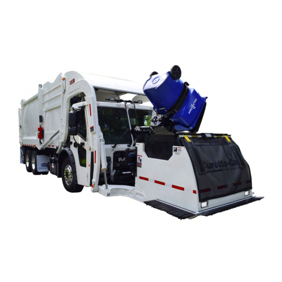
Page 46: Curotto-Can Nomenclature
Half/Pack ® Body and Tailgate CUROTTO-CAN NOMENCLATURE ITEM DESCRIPTION ITEM DESCRIPTION Curotto-Can Body Grabber Beam Subassembly Front Windscreen Gripper Arms x 2 Street Side Windscreen Fork Pocket Assembly x 2 Rear Spill Guard Hinge Main Assembly Curb Side Spill Guard Slide Cylinder Slide Assembly Gripper Arm Cylinder... -
Page 47: Curotto-Can Weekly Top Ten Checks
Half/Pack ® Body and Tailgate CUROTTO-CAN TOP WEEKLY CHECKS Always complete an Operational Lock-Out/Tag-Out before starting inspection. If any check does not complete successfully the Curotto-Can must be repaired before use otherwise the Warranty is void and equipment damage or operator injury could result. - Page 48 Half/Pack ® Body and Tailgate CUROTTO-CAN TOP WEEKLY CHECKS Always complete an Operational Lock-Out/Tag-Out before starting inspection. If any check does not complete successfully the Curotto-Can must be repaired before use otherwise the Warranty is void and equipment damage or operator injury could result.
- Page 49 Half/Pack ® Body and Tailgate CUROTTO-CAN TOP WEEKLY CHECKS Always complete an Operational Lock-Out/Tag-Out before starting inspection. If any check does not complete successfully the Curotto-Can must be repaired before use otherwise the Warranty is void and equipment damage or operator injury could result.
-
Page 50: Service Hoist Raise/Lower Operation
Half/Pack ® Body and Tailgate SERVICE HOIST RAISE/LOWER OPERATION Before attempting to raise and lower the body, be sure the unit is on a firm level surface with the Parking Brake ENGAGED and HOLDING. The service hoist controls are located on the street side of the unit. See Figure 45. The factory-supplied body props are located on both sides under the body and forward of the rear wheels. - Page 51 Half/Pack ® Body and Tailgate SERVICE HOIST RAISE/LOWER OPERATION (CONTINUED) A. Raising the Body 1. Empty body of all refuse. 2. Make sure that body is on firm, level ground with the Parking Brake engaged and holding. 3. CLOSE the manual override valve on the power unit – PUSH the knob IN and turn it CLOCKWISE. 4.
-
Page 52: Tailgate Support Props
Half/Pack ® Body and Tailgate TAILGATE SUPPORT PROPS Two support props are on the unit and must be used whenever the tailgate is opened for service or maintenance. Both props must be used. DANGER A tailgate in motion is dangerous. Serious injury or death may occur if a person is struck by a moving tailgate or becomes trapped between the tailgate and the body. -
Page 53: Side Access Door
Half/Pack ® Body and Tailgate SIDE ACCESS DOOR A hinged access door is located on the street side of the unit and provides access to the body area for cleanout purposes. Never enter the door unless the truck engine is stopped, the ignition key is removed, and the unit is in Lock-Out/Tag-Out mode . -
Page 54: Side Access Door Proximity Switch
Half/Pack ® Body and Tailgate SIDE ACCESS DOOR PROXIMITY SWITCH One 18mm sourcing or sinking proximity switch located by the side access door. This switch is adjusted properly when the sensing gap between switch and target is 1/8”. See the figure below. NOTICE Side door must be closed and latched prior to adjustment of the side door proximity switch. -
Page 55: Main Underbody Valve
Half/Pack ® Body and Tailgate MAIN UNDERBODY VALVE The Under Body Valve is a Proportional Control Valve. We can control how much hydraulic oil goes to these circuits by shifting the valve spools small or large amounts. This is done with Pulse Width Modulation (PWM). Instead of just 12v turning on and off a valve coil, with PWM we can control what the coil receives so we can adjust speeds and cushion the cylinders. -
Page 56: Body Valve To Curotto And Tailgate
Half/Pack ® Body and Tailgate BODY VALVE TO CUROTTO AND TAILGATE VALVES Issued April 2018 Copyright 2018, Heil Environmental Body and Tailgate Printed in the U.S.A. -
Page 57: Instructions Of Inspection For Over-Packing
Half/Pack ® Body and Tailgate INSTRUCTIONS OF INSPECTION FOR OVER-PACKING Use the instructions that follow and perform the inspections necessary and any necessary actions due to damage to the unit from over-packing. A. Prepare the Unit for Inspection of Cracks 1. - Page 58 Half/Pack ® Body and Tailgate INSTRUCTIONS OF INSPECTION FOR OVER-PACKING (CONTINUED) C.Over-Packing Inspections 1. Thoroughly clean the inside and outside of the body before you inspect the unit for cracks. 2. Inspect for cracks in the metal of the unit as shown in the following illustrations. (The red dots indicate the inspection points.) Check both sides of the body.
-
Page 59: Welding And Electronic Devices / Electrical Lubricants
Half/Pack ® Body and Tailgate INSTRUCTIONS OF INSPECTION FOR OVER-PACKING (CONTINUED) C.Over-Packing Inspections (Continued) 3. If cracks are visible, contact your Heil dealer or Heil for recommended countermeasures. Continued operation of a vehicle with cracks can lead to detrimental damage to the structure that may or may not be repairable. 4. - Page 60 Half/Pack ® NOTES Issued April 2018 Copyright 2018, Heil Environmental Maintenance and Adjustment Printed in the U.S.A.
-
Page 61: Maintenance And Adjustment
Half/Pack ® Maintenance and Adjustment SECTION 4 MAINTENANCE AND ADJUSTMENT Copyright 2018, Heil Environmental Issued April 2018 Maintenance and Adjustment Printed in the U.S.A. -
Page 62: Body Daily Checklist
Half/Pack ® Maintenance and Adjustment BODY DAILY CHECKLIST Make sure you perform a daily check of the unit. Refer to the Operator’s Manual for the Daily Checklist. Many checks in the Daily Checklist are maintenance related, such as checking tire pressures and hoses for wear and damage. DAILY CHECKLIST MAINTENANCE ITEMS ITEM REQUIRED ACTION... -
Page 63: Body Preventive Maintenance Chart
Half/Pack ® Maintenance and Adjustment BODY PREVENTIVE MAINTENANCE CHART Preventive maintenance must be performed to ensure the safe and reliable operation of your unit. Use the chart below as a guideline for when essential items should checked and serviced. Severe use or adverse conditions may require more frequent maintenance. - Page 64 Half/Pack ® Maintenance and Adjustment BODY PREVENTIVE MAINTENANCE CHART *HOURS OF OPERATION COMPONENT/SYSTEM 1000 2000 CHECK/SERVICE Lubricate as shown on Body Grease Fittings Lubrication Guide Inspect body undercoating and repair Body Undercoating as necessary. Each of the four fork bearing block bolt Fork Bearing Block Bolts torques should be 460 Ft-Lbs.
-
Page 65: Body Lubrication Guide
Half/Pack ® Maintenance and Adjustment BODY LUBRICATION GUIDE Clean fittings before applying grease and always pump enough grease into joint to remove the old grease. Wipe off excess grease. Lubricate moveable mechanical parts without fittings every 60 days with non-detergent engine oil. Copyright 2018, Heil Environmental Issued April 2018 Maintenance and Adjustment... -
Page 66: Curotto-Can Lubrication Guide
Half/Pack ® Maintenance and Adjustment CUROTTO-CAN LUBRICATION GUIDE Clean fittings before applying grease and always pump enough grease into joint to remove the old grease. Wipe off excess grease. Lubricate moveable mechanical parts without fittings every 60 days with non-detergent engine oil. The Curotto-Can comes standard with a multiple point lubrication system or with an optional single point lubrication system. -
Page 67: Curotto-Can Optional Single Point Lubrication Guide
Half/Pack ® Maintenance and Adjustment CUROTTO-CAN OPTIONAL SINGLE POINT LUBRICATION GUIDE Clean fittings before applying grease and always pump enough grease into joint to remove the old grease. Wipe off excess grease. Lubricate moveable mechanical parts without fittings every 60 days with non-detergent engine oil. The Curotto-Can comes standard with a multiple point lubrication system or with an optional single point lubrication system. -
Page 68: Pack/Eject Cylinders Maintenance
Half/Pack ® Maintenance and Adjustment PACKER/EJECTOR CYLINDERS PREVENTIVE MAINTENANCE It is critical to follow the guidelines of the Body Preventive Maintenance Chart and Body Lubrication Guide found in this section of this Service Manual and the Body Lubrication Guide decal on the unit. Failure to follow stated routine preventive maintenance can lead to premature cylinder failure that is not covered by your warranty. -
Page 69: Insight Diagnostic Display
Half/Pack ® Maintenance and Adjustment The Heil InSight Display is the information center for the operator and troubleshooting tool for the service mechanic. The next few pages cover basic functionality. For additional information, see Dedicated Half/Pack Factor AFL Cortex in the Body Controller Software section of this manual. -
Page 70: Diagnostic Display Messages
Half/Pack ® Maintenance and Adjustment DIAGNOSTIC DISPLAY MESSAGES When a fault occurs, the In-Cab Alarm will sound and a diagnostic message will be displayed with the status of respective Input / Output in the Insight display unit. See the figure below. See Body Controller Software Section for display screen shots of potential diagnostic messages, listed disabled functions and instructions for fault reset. -
Page 71: Inputs / Outputs
Half/Pack ® Maintenance and Adjustment INPUTS / OUTPUTS A. Inputs Inputs are signals the controller receives from sensors or switches. Examples being: Prox switch signals, fork cylinder sensors, arm cylinder sensors, packer position sensor, pump on/off push button, system power button, packer extend or retract push buttons and so on. - Page 72 Half/Pack ® Maintenance and Adjustment INPUTS / OUTPUTS (CONTINUED) B. Outputs Outputs are signals sent out of the Cortex Controller to turn something ON or to make something happen. Any signal that is sent out of the controller is an output. Output examples are: Signals sent to valve coils that move a valve spool or to turn on a light.
-
Page 73: Service Mode
Half/Pack ® Maintenance and Adjustment SERVICE MODE event of a Cylinder or Packer Sensor failure on route to recover to a safe arms and forks position. Service Mode can also be used to move the functions while servicing a failed Cylinder Sensor. NOTICE Service Mode is to be used ONLY by authorized service personnel. -
Page 74: Cylinder Sensors
Half/Pack ® Maintenance and Adjustment CYLINDER SENSORS Half/Pack (featuring Odyssey Controls) uses linear position sensors inside the street side arm and fork cylinders to transmit recommended to calibrate these sensors annually to compensate for mechanical drifting of components. See Cylinder Sensors / Arc Sensor Calibration. - Page 75 Half/Pack ® Maintenance and Adjustment CYLINDER SENSORS CALIBRATION (CONTINUED) NOTICE The arms, forks and packer will move very, very slow due to the unit being in Calibration Mode. 2. Perform the calibration steps below. a. Place Arms all the way DOWN and fully retract the Packer Blade – press OK (the display will move to the next screen) b.
-
Page 76: Cold Weather Warmup Procedure
Half/Pack ® Maintenance and Adjustment COLD WEATHER WARM-UP PROCEDURE When ambient air temperature is cold (below 0 degrees F), it is necessary to warm up the unit’s hydraulic oil before you start your daily route operation or to check the oil level. The hydraulic oil is sufficiently warmed when the temperature is between 120°... -
Page 77: Preparing The Unit To Check The Oil Level
Half/Pack ® Maintenance and Adjustment PREPARING THE UNIT TO CHECK THE OIL LEVEL Before checking the oil level or adding oil, make sure the unit is in the following position with all cylinders collapsed: Truck – on level ground Tailgate and Body – fully down and locked Packer Panel –... -
Page 78: Check Oil Level
Half/Pack ® Maintenance and Adjustment CHECK OIL LEVEL Check the hydraulic oil level (after warning up the oil) daily or every eight (8) hours, whichever comes first. Fill as necessary. Important: Contamination is a hydraulic system’s worst enemy. Do not let dirt enter the system. Use a clean rag and remove dirt or other contamination around any system component before you disconnect or remove it. -
Page 79: Drain And Clean The Hydraulic Oil Tank
Half/Pack ® Maintenance and Adjustment DRAIN AND CLEAN THE HYDRAULIC OIL TANK Change the hydraulic oil at least annually or every 2000 hours of operating time, whichever comes first. Remember that almost all hydraulic system malfunctions can be traced to dirt in the fluid. When working with the hydraulic system, the hands, tools, working area and parts must be as clean as possible. -
Page 80: Pressure Adjustment Procedures
Half/Pack ® Maintenance and Adjustment DRAIN AND CLEAN THE HYDRAULIC OIL TANK (CONTINUED) NOTICE Before filling the tank be sure the funnel is clean and 200 mesh (or finer) screen is used to strain the hydraulic oil. 13.Fill tank with recommended oil, checking the sight gauge as you fill. Refer to Hydraulic Oil Specifications 14.Check the entire system to make sure all connections are tight and no leaks are found. - Page 81 Half/Pack ® Maintenance and Adjustment B. Required Tools These are the tools required to make pressure adjustments. Quantity Tool 1/8” open end wrench Ratchet with screwdriver attachment 0-5000 PSI hydraulic pressure gauge C.Valve Locations The hydraulic control valves are located on the street side of the body. The main body valve that controls the packer, arms, forks, and auxiliary (Curotto-Can valve and tailgate valve flow diverter) hydraulic circuits is located beneath the body and behind a steel cover as seen in the left figure below, at the arrow location.
- Page 82 Half/Pack ® Maintenance and Adjustment PRESSURE ADJUSTMENT PROCEDURES (CONTINUED) D.Pressures and Cycle Times Half/Pack Factor AFL Diesel 2800 PSI 2800 PSI MAIN RELIEF @1200 ENGINE RPM STANDARD/SIERRA STANDARD/SIERRA PACKER EXTEND 2650 PSI 2650 PSI SIERRA/FREEDOM SIERRA/FREEDOM 2000 PSI 2000 PSI 2650 PSI 2650 PSI PACKER RETRACT...
-
Page 83: Clamp-On Arm Bolts Maintenance
Half/Pack ® Maintenance and Adjustment PRESSURE ADJUSTMENT PROCEDURES (CONTINUED) D.Pressures and Cycle Times (Continued) 1. Main Pressure settings have a tolerance range of +/- 50 p.s.i. and are to be set at operating speed - WI594 2. Port Relief Pressure settings have a tolerance range of +/- 100 p.s.i. and are to be set at operating speed - WI594 3. -
Page 84: Cracked Weld Joints
Half/Pack ® Maintenance and Adjustment REPAIRING CRACKED WELD JOINTS Repair all cracked weld joints immediately after finding cracked weld joints. If you are unsure of the proper repair procedure, call Heil Technical Services at 866-310-4345. CLEAN AND INSPECT THE TAILGATE SEAL Periodically check the tailgate seal to make sure it mates properly with the body and inspect for possible wear, damage or leaking. - Page 85 Half/Pack ® Body Controller Hardware SECTION 5 BODY CONTROLLER HARDWARE Copyright 2018, Heil Environmental Issued April 2018 Body Controller Hardware Printed in the U.S.A.
-
Page 86: Body Controller Hardware
Half/Pack ® Body Controller Hardware The 32-bit, 80 I/O Cortex Controller is located midway within the street side of the body behind a steel cover. See the image below and Body Controller Hardware section Figure 22. Cortex Controller Location The 32 I/O Cortex Controller Module is located on the street side of the body behind a steel cover, left of the tailgate valve. Figure 23. - Page 87 Half/Pack ® Body Controller Hardware For residential, dedicated Curotto-Can units, see the image below and component descriptions on the next page. Figure 24. Cortex Controller and Module Components Copyright 2018, Heil Environmental Issued April 2018 Body Controller Hardware Printed in the U.S.A.
- Page 88 Half/Pack ® Body Controller Hardware ITEM PART NUMBER DESCRIPTION QTY NOTES 474-0004-003 KIT, UNIT, DEDICATED CAN 047-2151-011 1/4" 14X11" LG TEK SCREW #3 047-2621-375 SCREW, BUTTON, HEAD CAP 054-5449-A 1/4" O.D. BLACK AIR LINE 054-8470-004 AIR LINE CONNECTOR ELBOW 075-0721 FILTER/REGULATOR W/GAUGE 108-7691 ROCKER SW, MAINTAINED, DPST...
-
Page 89: Programming Cables And Adapters
Half/Pack ® Body Controller Hardware For residential units, remote controller nodes reduce wiring in the body harness and decrease troubleshooting time, i.e. if power ground and signal are going to node, the tech then knows issues is between node and valve. Contact Heil Environmental for re-programming of the Cortex Controller. - Page 90 Half/Pack ® Body Controller Hardware Issued April 2018 Copyright 2018, Heil Environmental Body Controller Hardware Printed in the U.S.A.
- Page 91 Half/Pack ® Body Controller Hardware 80 I/O ASSEMBLY Copyright 2018, Heil Environmental Issued April 2018 Body Controller Hardware Printed in the U.S.A.
- Page 92 Half/Pack ® Body Controller Hardware Figure 25. 80 I/O Cortex Controller Hardware Issued April 2018 Copyright 2018, Heil Environmental Body Controller Hardware Printed in the U.S.A.
-
Page 93: Pin Number Diagram
Half/Pack ® Body Controller Hardware plastic for pin numbers 1 and 19 (top row left to top row right), 20 and 37 (middle row left to middle row right), and 38 and 55 (bottom row left and bottom row right). Figure 26. - Page 94 Half/Pack ® Body Controller Hardware Follow these steps to assemble the Cortex Controller Cable. A. Cable and Controller Parts Identification See the figure below to identify the 55-Pole Cable Connector parts. Figure 27. Cable Controller Plastic Male Hinge Pins and Controller Female Slot Connectors Issued April 2018 Copyright 2018, Heil Environmental Body Controller Hardware...
- Page 95 Half/Pack ® Body Controller Hardware B. Female Controller Connector Close-Up View See the figure below to identify the controller female connector. Figure 28. Female Controller Connector Slots Copyright 2018, Heil Environmental Issued April 2018 Body Controller Hardware Printed in the U.S.A.
- Page 96 Half/Pack ® Body Controller Hardware C.Connecting the 55-Pole Cable Connector Refer to the figure below and then slide cable male connectors into controller female connectors. Figure 29. Cable Connector Pivoting on Controller Issued April 2018 Copyright 2018, Heil Environmental Body Controller Hardware Printed in the U.S.A.
- Page 97 Half/Pack ® Body Controller Hardware D.Pivot Cable Connector and Latch 1. While keeping left side of cable connector seated, carefully pivot cable connector until flush with controller. See the figure below. Figure 30. Slowly Press Down While Keeping Left Cable Connector Pivot Point in Place 2.
- Page 98 Half/Pack ® Body Controller Hardware Issued April 2018 Copyright 2018, Heil Environmental Body Controller Hardware Printed in the U.S.A.
- Page 99 Half/Pack ® Body Controller Software SECTION BODY CONTROLLER SOFTWARE Copyright 2018, Heil Environmental Issued April 2018 Body Controller Software Printed in the U.S.A.
-
Page 100: Body Controller Software
Half/Pack ® Body Controller Software 051517) Section 1: CORTEX32 Controller Hardware 1.01: CORTEX32 Controller Indicator Lights The 2018 Dedicated Half/Pack Factor AFL vehicle control system consists of 3 CORTEX32 Controllers. The “MAIN” CORTEX32 Controller is an Extended Controller consisting of 80 Inputs / Outputs, the Remote Tailgate CORTEX32 Controller (“RTG”) and the Remote Can CORTEX32 Controller (“RCN”)* is a Standard Controller consisting of 32 Inputs / Outputs. - Page 101 Half/Pack ® Body Controller Software Note 3 : Applicable only for Remote Tailgate CORTEX32 Controller (“RTG”) and the Remote Can CORTEX32 Controller (“RCN”). 1.02: Inputs The CORTEX32 Controller Inputs are activated by positive +12 volt signals and some Ground signals (some chassis signals).
- Page 102 Half/Pack ® Body Controller Software Figure: Pulse Width Modulation (PWM) Output Waveforms 1.04: Communication Ports There are 4-CAN and 1-RS-232 communication port in the 80 I/O CORTEX32 Controlle r which will be utilized for the programming and communication purposes. The Serial port (RS-232) in the ST side will be utilized to download user programs via CORTEX Download tool (Downloader 32) and CAN ports in the ST side for communication between Controller and field devices.
- Page 103 Half/Pack ® Body Controller Software PROGRAM NUMBER: 109-0305 CONNECTOR REVISION NUMBER: 2016xxxx CONTROLLER PIN-OUT TYPE ADDRESS DETAILS HALF/PACK FACTOR AFL 80 I/O RESIDENTIAL (DEDICATED CAN) A04 LEFT TURN SIGNAL MAIN %IX0.13 P1-39 A05 RIGHT TURN SIGNAL MAIN %IX0.11 P1-40 A06 TRANSMISSION TEMP. SIGNAL SWITCH MAIN %IX0.15 P1-38...
- Page 104 Half/Pack ® Body Controller Software PROGRAM NUMBER: 109-0305 CONNECTOR REVISION NUMBER: 2016xxxx CONTROLLER PIN-OUT TYPE ADDRESS DETAILS HALF/PACK FACTOR AFL 80 I/O RESIDENTIAL (DEDICATED CAN) D08 CAB PROTECTOR UP MAIN %QX0.03 P1-15 D09 CAB PROTECTOR DOWN MAIN %QX0.02 P1-16 D10 ALLISON PTO ENABLE MAIN %QX0.00 P1-18...
- Page 105 Half/Pack ® Body Controller Software PROGRAM NUMBER: 109-0305 CONNECTOR REVISION NUMBER: 2016xxxx CONTROLLER PIN-OUT TYPE ADDRESS DETAILS HALF/PACK FACTOR AFL 80 I/O RESIDENTIAL (DEDICATED CAN) G02 CARRY CAN COVER DOWN %QX0.11 P1-5 G03 TAILGATE CAMERA OUTPUT MAIN %QX128.03 P2-15 G04 HOPPER CAMERA OUTPUT MAIN %QX128.02 P2-16...
- Page 106 Half/Pack ® Body Controller Software PROGRAM NUMBER: 109-0305 CONNECTOR REVISION NUMBER: 2016xxxx CONTROLLER PIN-OUT TYPE ADDRESS DETAILS HALF/PACK FACTOR AFL 80 I/O RESIDENTIAL (DEDICATED CAN) DUAL CONTROL PANEL BOX WHICH FUNCTIONS USING PANEL SELECTOR SWITCH CAN IN-CAB INPUT FUNCTIONS HYDRAULIC PUMP ENABLE PUSH BUTTON LOWER BANK PACKER EXTEND PUSH BUTTON LOWER BANK...
- Page 107 Half/Pack ® Body Controller Software PROGRAM NUMBER: 109-0305 CONNECTOR REVISION NUMBER: 2016xxxx CONTROLLER PIN-OUT TYPE ADDRESS DETAILS HALF/PACK FACTOR AFL 80 I/O RESIDENTIAL (DEDICATED CAN) K03 AUXILLIARY ARMS LOWER SWITCH K04 AUXILLIARY FORKS RAISE SWITCH K05 AUXILLIARY FORKS LOWER SWITCH K06 AUXILLIARY PACKER EXTEND SWITCH K07 AUXILLIARY PACKER RETRACT SWITCH K08 AUXILLIARY CUROTTO CONTROLS ENABLE SWITCH...
- Page 108 Half/Pack ® Body Controller Software Section 2: J1939 Details The Engine information is directly read through the SAE J1939 standard. SAE J1939 is the vehicle bus standard used for communication and diagnostics among vehicle components, like heavy duty truck industry. J1939 is used in heavy vehicles for on-street and off-road operations and works on the physical layer with CAN-high speed according to ISO11898.
- Page 109 Half/Pack ® Body Controller Software Function Logic: Input Device Status I/O Address Status System Power Switch Activated %IX0.08 A02 Input Function – Chassis Neutral Signal (In Cab Input %IX0.10) This circuit monitors the transmission Neutral circuit. Condition Modifiable Parameters Default Setting None Function Logic: Input Device...
- Page 110 Half/Pack ® Body Controller Software None Function Logic: Input Device Status I/O Address Status Turn Signal Enable Circuit Activated %IX0.11 A06 Input Function – Transmission Temperature Signal Switch (In Cab Input %IX0.15) This circuit monitors the status of the Transmission Oil Temperature. The input is ON when the Temperature of the Transmission Oil is OK.
- Page 111 Half/Pack ® Body Controller Software 4.02: Standard In-Cab Output Functions B01 Output Function – In-Cab Alarm (In Cab Output %QX128.08) This output function controls the In-Cab Alarm. See Section 6.04 for a complete explanation of the Diagnostic Messages associated with this unit. Condition Modifiable Parameters Default Setting None...
- Page 112 Half/Pack ® Body Controller Software Condition Modifiable Parameters Default Setting None Conditions Necessary to activate the circuit: Condition Function or Component Status I/O Address Status Pump On Activated Neutral Signal Activated %IX0.10 ON (See Note Below) Throttle Advance Output Deactivated %QX0.10 Note: With condition ‘A’...
- Page 113 Half/Pack ® Body Controller Software Condition Modifiable Parameters Default Setting None Function Logic: Input Device Status I/O Address Status Filter Pressure Switch Activated %IX0.06 C02 Input Function -- Side Door Closed Proximity Switch (Body Input %IX0.04) This circuit monitors the ON/OFF status of the Side Door Closed Proximity Switch. The input is ON when the side door is closed.
- Page 114 Half/Pack ® Body Controller Software C05 Input Function – Forks Tucked Proximity Switch (Body Input %IX0.03) This circuit monitors the ON/OFF status of the Forks Tucked Proximity Switch. The input is ON when the Forks are fully tucked position. NOT USED. Condition Modifiable Parameters Default Setting None...
- Page 115 Half/Pack ® Body Controller Software 4.04: Standard Body Output Functions D01 Output Function – Tailgate Up Solenoid (Body Output %QX0.02) This output function controls the Tailgate Up output circuit. Condition Modifiable Parameters Default Setting None Conditions Necessary to activate the circuit: Condition Function or Component Status...
- Page 116 Half/Pack ® Body Controller Software D03 Output Function – Tailgate Lock Solenoid (Body Output %QX0.04) This output function controls the Tailgate Lock output circuit. Condition Modifiable Parameters Default Setting None Conditions Necessary to activate the circuit: Condition Function or Component Status I/O Address Status...
- Page 117 Half/Pack ® Body Controller Software Conditions Necessary to activate the circuit: Condition Function or Component Status I/O Address Status Tailgate Closed Prox. Deactivated %IX0.00 Tailgate Locked Prox. Deactivated %IX0.00 Note: If Tailgate is not closed OR if Tailgate is not Locked i.e. if condition (A OR B) is true, then Back Up Alarm is activated.
- Page 118 Half/Pack ® Body Controller Software Condition Function or Component Status I/O Address Status Arms Down Interlock Deactivated Aux Controls Enable Activated ON (Manual Control – Var. speed) Aux Arms Lower Activated ON (Manual Control – Var. speed) Sensor Failure Deactivated Lower Arms Activated Note: The Arms Valve PWM output provides flow to the hydraulic hoses on the Arms cylinder.
- Page 119 Half/Pack ® Body Controller Software Condition Function or Component Status I/O Address Status Side Door Prox. Switch Activated %IX0.4 Road Speed Activated ON (see Note below) Engine Speed Activated ON (see Note below) Filter Bypass Deactivated Filter Pressure Switch Activated %IX0.6 Low Oil Level Switch Activated...
- Page 120 Half/Pack ® Body Controller Software Conditions Necessary to activate the circuit: Condition Function or Component Status I/O Address Status Pump Enable Push Button Activated System Power Switch Activated %IX0.8 Side Door Prox. Switch Activated %IX0.4 Road Speed Activated ON (see Note below) Engine Speed Activated ON (see Note below)
- Page 121 Half/Pack ® Body Controller Software Condition Function or Component Status I/O Address Status NOT USED D15 Output Function – Curotto - Carry Can Up (Body Output %QX0.06) This function controls the Curotto - Carry Can Up signal. Condition Modifiable Parameters Default Setting None Conditions Necessary to activate the circuit:...
- Page 122 Half/Pack ® Body Controller Software and Scale Alarm 2 Deactivated %IX128.2 OFF (See Section A04) and Pump On Activated Bayne Down Activated Pump On Activated Stow Can Activated Note: This signal is energized using a CAN based control by energizing the Carry Can Down switch either from Street side or from Curb side panel.
- Page 123 Half/Pack ® Body Controller Software None Conditions Necessary to activate the circuit: Condition Function or Component Status I/O Address Status Panel Selector Switch Activated %IX0.09 and Carry Can Auxiliary Enable Switch Deactivated Carry Can Out Activated and Carry Can Auxiliary Enable Switch Activated and Autolift Enable Switch Activated...
- Page 124 Half/Pack ® Body Controller Software D20 Output Function – Curotto - Carry Can Release (Body Output %QX0.01) This function controls the Curotto - Carry Can Release signal. Condition Modifiable Parameters Default Setting None Conditions Necessary to activate the circuit: Condition Function or Component Status I/O Address Status...
- Page 125 Half/Pack ® Body Controller Software D21 Output Function – Tailgate Enable PWM control (Body Output %QX0.14) This output function controls the Tailgate PWM control output circuit. Condition Modifiable Parameters Default Setting None Conditions Necessary to activate the circuit: Condition Function or Status I/O Address Status...
- Page 126 Half/Pack ® Body Controller Software F01 Input Function – High Pressure Filter Switch (Body Input %IX128.4) This circuit monitors the ON/OFF status of the High Pressure Filter Switch. Condition Modifiable Parameters Default Setting None Function Logic: Input Device Status I/O Address Status High Pressure Filter Switch Activated...
- Page 127 Half/Pack ® Body Controller Software Cab Protector Down Prox. Switch Activated %IX0.14 F05 Input Function -- Tailgate Locked Proximity Switch (Body Input %IX0.02) This circuit monitors the ON/OFF status of the Tailgate Locked Proximity Switch i.e. it indicates the position of the Tailgate lock cylinders. The input is ON when the Tailgate cylinder is locked. Condition Modifiable Parameters Default Setting None...
- Page 128 Half/Pack ® Body Controller Software Function Logic: Input Device Status I/O Address Status External Throttle Advance Switch Activated %IX128.06 4.08: Optional Body Output Functions G01 Output Function – Curotto - Carry Can Cover Up (Body Output %QX0.10) This function controls the Curotto - Carry Can Cover Up signal. Condition Modifiable Parameters Default Setting None...
- Page 129 Half/Pack ® Body Controller Software Conditions Necessary to activate the circuit: Condition Function or Component Status I/O Address Status NOT USED G04 Output Function – Hopper Camera Output (Body Output %QX128.02) Condition Modifiable Parameters Default Setting None Conditions Necessary to activate the circuit: Condition Function or Component Status...
- Page 130 Half/Pack ® Body Controller Software Pump On Activated Reverse Activated Turn Signal Deactivated Note: The Strobe light circuit-2 can be turned ON in following conditions: With Pump ON or Reverse signal activated or Strobe switch ON If the unit is configured with Whelen strobes, the strobes are ON in the above conditions with Turn signal being deactivated.
- Page 131 Half/Pack ® Body Controller Software None Conditions Necessary to activate the circuit: Condition Function or Status I/O Address Status Component Container Light Switch Activated Note: With condition ‘A’ true, will activate the Container Light Output signal either from Street side or from Curb Side of the dual control panel unit.
- Page 132 Half/Pack ® Body Controller Software None Function Logic: Input Device Status I/O Address Status Packer Position Activated %IW02 VOLTAGE H02 Input Function – Oil Tank Temperature (Analog Input %IW14) This circuit measures the Hydraulic Oil Temperature. Condition Modifiable Parameters Default Setting None Function Logic: Input Device...
- Page 133 Half/Pack ® Body Controller Software I02 Input Function -- Packer Extend Input (CAN - In Cab Input) This CAN control is used to turn ON/OFF the Packer Extend control either from Street side or from the Curb side of a dual control panel unit. Condition Modifiable Parameters Default Setting None...
- Page 134 Half/Pack ® Body Controller Software Function Logic: Input Device Status I/O Address Status Select-O-Pack Input Activated ON (CAN Control) I06 Input Function – CAB Cover Raise Switch Circuit (CAN - In Cab Input) This CAN control is used to raise the Cab protector shield, either from Street side or from the Curb side of a dual control panel unit.
- Page 135 Half/Pack ® Body Controller Software Condition Modifiable Parameters Default Setting None Function Logic: Input Device Status I/O Address Status Tailgate Lower Input Activated ON (CAN Control) I10 Input Function – Tailgate Lock Switch (CAN - In Cab Input) This CAN control is used to lock the Tailgate, either from Street side or from the Curb side of a dual control panel unit.
- Page 136 Half/Pack ® Body Controller Software 4.11: MULTI FUNCTION JOYSTICK CONTROL INPUT FUNCTIONS The Multifunction Joystick control can operate in 2 modes: 1. Carry Can mode: If the Autolift switch is enabled (turned ON), then the Joystick is used for controlling the carry can operations.
- Page 137 Half/Pack ® Body Controller Software Condition Modifiable Parameters Default Setting None Function Logic: Input Device Status I/O Address Status Y-Axis Positive direction Activated ON (CAN Control) J05 Input Function – Joystick – X-AXIS (Negative Direction) (CAN – Cab Input) 1. Carry Can mode: Moving the Joystick Left (X-axis in Negative direction) makes the Curotto can Arm retract. 2.
- Page 138 Half/Pack ® Body Controller Software Input Device Status I/O Address Status Auto lift Mode Button Activated ON (CAN Control) J08 Input Function – Joystick – Operator presence (CAN – Cab Input) Joystick operator presence input is a capacitive sensor embedded in the Multi-function joysticks that is activated when the operators hand is placed around the joystick handle.
- Page 139 Half/Pack ® Body Controller Software Condition Modifiable Parameters Default Setting None Function Logic: Input Device Status I/O Address Status Auxiliary Arms Lower Activated ON (CAN Control) K04 Input Function – Auxiliary Forks Raise Switch (CAN - In Cab Input) This Auxiliary CAN control is used to turn ON the - Forks Raise switch using Auxiliary control. This input is operative only if Auxiliary Controls Enable Switch is ON (Refer K01).
- Page 140 Half/Pack ® Body Controller Software K07 Input Function – Auxiliary Packer Retract (CAN - In Cab Input) This Auxiliary CAN control is used to turn ON the - Packer Retract switch using Auxiliary control. This input is operative only if Auxiliary Controls Enable Switch is ON (Refer K01). Condition Modifiable Parameters Default Setting None...
- Page 141 Half/Pack ® Body Controller Software Auxiliary Curotto (Release) Switch Activated ON (CAN Control) K11 Input Function – Auxiliary Curotto (DUMP) Switch (CAN - In Cab Input) Here the Auxiliary Curotto control (DUMP) switch performs the Curotto Can Dump. This input will be active only if Auxiliary Curotto Control Enable Switch is ON (Refer K08).
- Page 142 Half/Pack ® Body Controller Software Function Logic: Input Device Status I/O Address Status Auxiliary Curotto (OUT) Switch Activated ON (CAN Control) 4.13: OPTION CAN In-Cab Input Functions L01 Input Function – Travel Position Switch (CAN - In Cab Input) This CAN control is used to turn ON/OFF the Travel position Signal of the Packer, either from Street side or from the Curb side of a dual control panel unit.
- Page 143 Half/Pack ® Body Controller Software L04 Input Function – Top Door Close Switch (CAN - In Cab Input) This CAN control is used to close the Top Door during the Travel position Signal of the Packer, either from Street side or from the Curb side of a dual control panel unit. Condition Modifiable Parameters Default Setting None...
- Page 144 Half/Pack ® Body Controller Software Function Logic: Input Device Status I/O Address Status Container Light Circuit Switch Activated ON (CAN Control) L08 Input Function – CAB Light Switch (CAN - In Cab Input) This CAN control is used to turn ON/OFF the forward facing Cab Light Circuit, either from Street side or from the Curb side of a dual control panel unit.
- Page 145 Half/Pack ® Body Controller Software Condition Modifiable Parameters Default Setting None Function Logic: Input Device Status I/O Address Status Curotto Can – Light Activated ON (CAN Control) Copyright 2018, Heil Environmental Issued April 2018 Body Controller Software Printed in the U.S.A.
- Page 146 Half/Pack ® Body Controller Software Section 5: Special Features 5.01: Auto Pack Mode Auto Pack is a standard feature on all CORTEX controlled FEL (Front End Loader) products. While in Auto Pack the Packer will complete its cycle automatically with a momentary activation of the Packer Extend push button. 5.02: Select-O-Pack Select-O-Pack is an option for Commercial FEL products and is standard on Residential FEL products.
- Page 147 Half/Pack ® Body Controller Software Fig.: 7” INSIGHT Display Unit The display is fitted with the following operating elements: 1. 9 Function Keys 2. 4 Directional Arrows (Up / Down / Right / Left) 3. OK Push Button 4. INSIGHT Display. 1.
- Page 148 Half/Pack ® Body Controller Software Fig.: 12” INSIGHT Display Unit The display is fitted with the following operating elements: 1. 13 Function Keys 2. 4 Directional Arrows (Up / Down / Right / Left) 3. OK Push Button 4. INSIGHT Display. 1.
- Page 149 Half/Pack ® Body Controller Software 5.04.03:Rear Panel Housing connection: Table below provides Wiring details for the Interface cable of INSIGHT display unit Copyright 2018, Heil Environmental Issued April 2018 Body Controller Software Printed in the U.S.A.
- Page 150 Half/Pack ® Body Controller Software 5.04.04:Interface details: 1. Ethernet Interface: Use a Shielded CAT5 cable (Shielded Twisted Pair - STP) for connection with maximum lebgth of 25 mts. 2. Ethernet Camera: The device supports Ethernet cameras. 3. USB Interface: The USB interfaces are used for temporary connection of an external keyboard, mouse or a USB memory stick during servicing or maintenance.
- Page 151 Half/Pack ® Body Controller Software Copyright 2018, Heil Environmental Issued April 2018 Body Controller Software Printed in the U.S.A.
- Page 152 Half/Pack ® Body Controller Software 5.05: Half/Pack Factor AFL Interlock Functionality 5.05.01: Residential Mode A. Curb Side Control 1. Manual mode: The angle of the Curotto-Can is limited and the location in the arm arc where the Curotto-Can can be adjusted is limited to below the Overheight position.
- Page 153 Half/Pack ® Body Controller Software Note: In Carry Can mode, all interlocks are active on the street side and curb side even with knob or 2-lever joysticks installed. Autolift function is not available with knob or 2-lever joystick. Copyright 2018, Heil Environmental Issued April 2018 Body Controller Software Printed in the U.S.A.
- Page 154 Half/Pack ® Body Controller Software Section 6: Diagnostic Messages and Alarms 6.01: Testing I/O Voltage To test the voltage at an input or output terminal a Digital Multi Meter is always the best tool. Incandescent test lights cannot be used to test inputs from certain electronic input devices, the amperage required to light an incandescent tester may exceed the maximum output of the device.
- Page 155 Half/Pack ® Body Controller Software With an Input ON, the corresponding Input field (with Description and Address) located in INSIGHT display will also be Refer section 5.04 for more details about Diagnostic display options and INSIGHT display tool. 6.03: Monitoring Output Status With an Output ON, the corresponding Output field (with Description and Address) located in INSIGHT display will also be Refer section 5.04 for more details about Diagnostic display options and INSIGHT display tool.
- Page 156 Half/Pack ® Body Controller Software 6.04: Diagnostic Display Messages When a fault has been set the IN-Cab Alarm will sound and a Diagnostic message will be displayed with the status of respective Input / Output in the Insight display unit. Top Door Open and Auto Pack Interlock (standard equipment) If Top door is not fully open with the Top door configuration bit ON, Residential Curotto Configuration bit ON, Select-O- Pack option enabled and Travel position switch enabled or Packer Extend Push Button pressed, Top Door Open...
- Page 157 Half/Pack ® Body Controller Software Indication: A. Scale Alarm-2 ON due to Overweight. B. PTO-1 and PTO-2 pump Active signal ON. Disabled Functions: Arms Up interlock and Forks raise Interlock Fault Reset: Check Auto Lift Enable switch and check for Overweight condition for proper operation. Cab Protector Down with Arms Lowered Interlock and Arms Active and Arms up Interlock (standard equipment) The arms have been lowered when the top door is not fully open or the Arm position angle is greater than the Fork roll...
- Page 158 Half/Pack ® Body Controller Software C. Top Door Configuration bit is ON. D. Cab Protector Down Configuration bit is ON. Disabled Functions: Forks will not be Lowered. Fault Reset: Open the top door fully. Check top door, Cab protector down prox., Lift below Transit prox., Forks position and Arms position for proper operation.
- Page 159 Half/Pack ® Body Controller Software Indication: A. Top Door Open light ON. B. Residential Configuration bit is ON. C. Top Door Configuration bit is ON. Disabled Functions: Forks will not lowered. Fault Reset: Open the top door fully. Check top door, Lift below Transit prox., Forks position and Arms position for proper operation.
- Page 160 Half/Pack ® Body Controller Software Disabled Functions: Forks will not Lowered. Fault Reset: Open the top door fully. Check Cab protector down prox., Lift below Transit prox., Forks position and Arms position for proper operation. Travel Position Not Allowed Interlock Active (standard equipment) If Auto lift enable switch is turned ON from either street side or from the curb side of the dual control panel and Travel position switch is activated while the Packer Extend/Retract push button has been pressed or Packer extend/retract Auxiliary controls are activated, then the diagnostic message will be displayed in the Insight display.
- Page 161 Half/Pack ® Body Controller Software Indications: Packer Fully Extended and Tailgate Closed inputs are lit. Disabled Functions: None. Fault Reset: Manually retract the packer or open the tailgate. Copyright 2018, Heil Environmental Issued April 2018 Body Controller Software Printed in the U.S.A.
- Page 162 Half/Pack ® Body Controller Software Packer Retract Pressed While Retracted (standard equipment) If the packer is fully retracted but the packer return push button is still pressed or the Packer retract Auxiliary controls were activated, then the diagnostic message will be displayed in the Insight display. Insight Display Illustration: Indications: The packer was manually returned and the retract button was not released.
- Page 163 Half/Pack ® Body Controller Software Indications: Diagnostic message will be displayed in the Insight display. Packer extend prox. is not activated 35 seconds after start of extend cycle. Disabled Functions: Packer Extend Fault Reset: Check packer extend prox. switch for proper operation and adjustment. Operate packer above Engine idle.
- Page 164 Half/Pack ® Body Controller Software Indication: A. Arms are raised B. Packer Extend push button pressed. C. Packer Override switch OFF. Disabled Functions: Packer will not extend. Fault Reset: Lower the arms until the Arms Raised light goes out. Turn OFF the Packer extend Auxiliary controls.
- Page 165 Half/Pack ® Body Controller Software Side Door Open (standard equipment) If the side door was opened during a packing operation or the pump enable switch was turned ON or the Auxiliary control for Packer Extend / Retract was enabled while the side door was open, the diagnostic message will be displayed in the Insight display.
- Page 166 Half/Pack ® Body Controller Software Indication: The diagnostic message will be displayed in the Insight display. Disabled Functions: None Fault Reset: Release the Packer extend push button or Turn OFF the Auxiliary Controls. Packer Retract Has Timed Out (standard equipment) The CORTEX Controller has a timer to monitor packer extend and packer retract operations.
- Page 167 Half/Pack ® Body Controller Software Packer Retract And Extend At Same Time (standard equipment) If the Packer retract and extend push buttons have been pressed at the same time, then the diagnostic message will be displayed in the Insight display. Insight Display Illustration: Indication: The packer does not move.
- Page 168 Half/Pack ® Body Controller Software Disabled Functions: Packer extend. Fault Reset: Turn ON the pump. Hydraulic Filter Is In Bypass (standard equipment) If the hydraulic filter has been in bypass for more than 11 hours, then the diagnostic message will be displayed in the Insight display.
- Page 169 Half/Pack ® Body Controller Software Indication: A. Arms Overheight light ON. B. Top Door Open light ON. C. Scale Alarm-2 ON due to Overweight. D. PTO-1 and PTO-2 pump Active signal ON. Disabled Functions: Forks will not raise above windshield. Fault Reset: Open the top door fully.
- Page 170 Half/Pack ® Body Controller Software C. Scale Alarm-2 ON due to Overweight. D. PTO-1 and PTO-2 pump Active signal ON. E. Top Door Open Configuration bit is ON. Disabled Functions: Forks will not raise above windshield. Fault Reset: Open the top door fully. Restart packer panel. Check top door and packer retract prox. switches and Auto Lift Enable switch for proper operation.
- Page 171 Half/Pack ® Body Controller Software Indication: A. Packer Sensor faulty B. Sensor failure ON Disabled Functions: Packer functions and Fork function. Fault Reset: Check for the Faulty sensor or Sensor mounting position or calibrate the faulty sensor and also check Packer Cylinder for proper operation. Fork Sensor Fault (standard equipment) The Fork position value is less than ‘-100’...
- Page 172 Half/Pack ® Body Controller Software Arm Sensor Fault (standard equipment) The Arm position value is greater than ‘1100’ or less than ‘-100’ during the operation then the diagnostic message will be displayed in the Insight display. Also the value is not within the High or Low limit (do we need this statement as we have given the Hi limit in 1 st line) Insight Display Illustration: Indication: A.
- Page 173 Half/Pack ® Body Controller Software Insight Display Illustration: Indication: Low Hydraulic Oil Level Disabled Functions: Hydraulic Pump Fault Reset: Refill hydraulic oil tank. Oil Over Temperature Shutdown Fault (standard equipment) If the Hydraulic Oil temperature is greater than 190º F, then the diagnostic message will be displayed in the Insight display.
- Page 174 Half/Pack ® Body Controller Software High Temperature Fault (standard equipment) If the Hydraulic Oil temperature is greater than 180º F, then the diagnostic message will be displayed on the Insight display. Insight Display Illustration: Indication: A. Hydraulic Oil over temperature warning B.
- Page 175 Half/Pack ® Body Controller Software Indication: A. System Power input is not lit. B. Pump does not turn ON Disabled Functions: Body pump Fault Reset: Turn the system power ON before utilizing Pump push button. Tailgate Open Indicator and Road Speed limit fault (standard equipment) If the Tailgate is open when the Road speed is greater than 10mph i.e.
- Page 176 Half/Pack ® Body Controller Software further. Tailgate Unlocked and Road Speed High Interlock (standard equipment) If the Tailgate is unlocked when the Road speed is greater than 10mph i.e. if the Tailgate is unlocked when the unit is in motion, the diagnostic message will be displayed on the Insight display. NOTE: Tailgate operation can be performed only when the Road speed is less than 5mph.
- Page 177 Half/Pack ® Body Controller Software Indication: A. The filter bypass pressure switch has been disconnected. B. An open has occurred in the filter bypass input circuit. C. The filter pressure switch has failed to open. Disabled Functions: None. Fault Reset: Cycle System Power Switch or Restore filter pressure switch input to CORTEX Controller. Note: This fault is applicable on dry valve pump units only.
- Page 178 Half/Pack ® Body Controller Software Disabled Functions: None Fault Reset: When the Temperature returns to defined limit (i.e. within -100 to 4000), the switch will reset. If the switch does not reset, there is a possible problem with the Temperature switch or the harnessing. No Voltage on Extended Controller side Fault (Standard equipment) If the Voltage measured across VBB1_E, VBB2_E, VBB3_E, and VBB_RELAYIS_VOLTAGE terminal (i.e.
- Page 179 Half/Pack ® Body Controller Software Indication: A. No Ignition Voltage on Extended side controller. Disabled Functions: CORTEX32 Extended Controller. Fault Reset: When the Voltage (greater than 8 VDC) is available at these VBB terminals (VBB2_E and VBB_RELAYIS_VOLTAGE), CORTEX32 extended controller will turn ON and start functioning normally. If the extended controller doesn’t start, there is a possible problem with the CORTEX32 Extended controller or 55-Pin connector connection or the harnessing.
- Page 180 Half/Pack ® Body Controller Software Disabled Functions: None Fault Reset: Preheat Oil before route. Issued April 2018 Copyright 2018, Heil Environmental Body Controller Software Printed in the U.S.A.
-
Page 181: Compressed Natural Gas (Cng) Option
Half/Pack ® Compressed Natural Gas (CNG) Option SECTION 7 COMPRESSED NATURAL GAS (CNG) OPTION Copyright 2018, Heil Environmental Issued April 2018 Compressed Natural Gas (CNG) Option Printed in the U.S.A. -
Page 182: Important Safety Information
Half/Pack ® Compressed Natural Gas (CNG) Option IMPORTANT SAFETY INFORMATION NOTICE For CNG units, this Service Manual should be used in conjunction with any associated CNG System Manufacturer's Operation and Maintenance Manuals. Always read and understand all associated manuals alongside the Heil Operation Manual and Heil Parts and Service Manual before operating or servicing the unit. - Page 183 Half/Pack ® Compressed Natural Gas (CNG) Option IMPORTANT SAFETY INFORMATION (CONTINUED) A. Safety Notices Throughout this manual, safety notices are included to warn operators and maintenance technicians of the dangers associated with the described equipment operations and maintenance. Improper operation or maintenance procedures may cause serious injury or death.
- Page 184 Half/Pack ® Compressed Natural Gas (CNG) Option IMPORTANT SAFETY INFORMATION (CONTINUED) WARNING Avoid open flames and sparks near a compressed natural gas vehicle. WARNING Do not smoke cigarettes, cigars, or use any other lit or sparking items within 30 feet of a compressed natural gas vehicle or a dispensing/filling station.
-
Page 185: Compressed Natural Gas (Cng) Fuel Module
Half/Pack ® Compressed Natural Gas (CNG) Option COMPRESSED NATURAL GAS (CNG) FUEL MODULE A. Fuel Module Functions The CNG fuel tanks contain CNG at a pressure of 3,600 psi in USA, (3,000 psi in Canada). The CNG Fuel Module serves multiple functions within a natural gas vehicle (NGV) fuel system. These functions include: Storage tank refueling Storage tank pressure measurement... - Page 186 Half/Pack ® Compressed Natural Gas (CNG) Option COMPRESSED NATURAL GAS (CNG) FUEL MODULE (CONTINUED) B. Fuel Module Components (Continued) 4. Purge Valve Located inside the side maintenance access door, the purge valve, when loosened, purges CNG from the vehicle’s fuel control module to allow safe access to the filter assembly. Figure 33.
-
Page 187: Maintenance
Half/Pack ® Compressed Natural Gas (CNG) Option MAINTENANCE Routine maintenance of the compressed natural gas system in accordance with the Table 1. Inspection/Preventive Care Schedule (below) will ensure that the system and components are functioning properly. WARNING System components must not be under pressure during servicing. Servicing components under pressure may cause serious injury. -
Page 188: Preparation Before Maintenance
Half/Pack ® Compressed Natural Gas (CNG) Option PREPARATION BEFORE MAINTENANCE It is necessary to prepare the truck to be serviced. A mechanic’s initial focus while preparing the vehicle for service should be safety. The primary preparation involves relieving the pressure within the system BEFORE performing any maintenance procedures. -
Page 189: Cng Fuel Module Maintenance And Part Replacement
Half/Pack ® Compressed Natural Gas (CNG) Option CNG FUEL MODULE MAINTENANCE AND PART REPLACEMENT A. Fuel Filter Location / Access Procedure 1. Locate the fuel filter inside the side maintenance access door of the CNG Fuel Module 2. Follow instructions in Preparation before Maintenance to ensure pressure has been relieved. - Page 190 Half/Pack ® Compressed Natural Gas (CNG) Option CNG FUEL MODULE MAINTENANCE AND PART REPLACEMENT (CONTINUED) C.Procedure for Draining the Filter Bowl (Continued) 11.Open remaining tank valves if no leak is detected. 12.Check the high pressure gauge to confirm a rise in fuel pressure. NOTICE Low pressure gauge may not register pressure until vehicle ignition is turned "ON".
- Page 191 Half/Pack ® Compressed Natural Gas (CNG) Option CNG FUEL MODULE MAINTENANCE AND PART REPLACEMENT (CONTINUED) D.Fuel Filter Replacement Procedure (Continued) 1. Follow instructions in Preparation before Maintenance to ensure pressure has been relieved 2. Locate the fuel filter inside the CNG module. Locate this fuel filter following directions in Compressed Natural Gas (CNG) Fuel Module section.
- Page 192 Half/Pack ® Compressed Natural Gas (CNG) Option CNG FUEL MODULE MAINTENANCE AND PART REPLACEMENT (CONTINUED) E. Fuel Module Receptacle O-Ring Replacement Procedure (Continued) The O-ring seals, located in the inlets of the two (2) fueling receptacles, can wear or become damaged over time and with repeated use.
- Page 193 Half/Pack ® Compressed Natural Gas (CNG) Option CNG FUEL MODULE MAINTENANCE AND PART REPLACEMENT (CONTINUED) G.Defueling Receptacle Replacement Procedure 1. Follow directions in Truck Preparation to relieve pressure before performing any maintenance. A check engine light or fault code may illuminate if the gas pressure is too low. This should resolve when gas pressure is restored. 2.
- Page 194 Half/Pack ® Compressed Natural Gas (CNG) Option CNG FUEL MODULE MAINTENANCE AND PART REPLACEMENT (CONTINUED) H.NGV1 Receptacle Replacement Procedure 1. Follow directions in Truck Preparation to relieve pressure before performing any maintenance. CAUTION A check engine light or fault code may illuminate if the gas pressure is too low. This should resolve when gas pressure is restored.
- Page 195 Half/Pack ® Compressed Natural Gas (CNG) Option CNG FUEL MODULE MAINTENANCE AND PART REPLACEMENT (CONTINUED) H.NGV1 Receptacle Replacement Procedure (Continued) CAUTION Be very careful not to cut or damage the new O-ring with the threads of the bulkhead fitting during installment of the O- ring.
- Page 196 Half/Pack ® Compressed Natural Gas (CNG) Option CNG FUEL MODULE MAINTENANCE AND PART REPLACEMENT (CONTINUED) I. Transit Fill Receptacle Replacement Procedure (Continued) CAUTION Allow pressure to bleed down completely before removing the receptacle. 6. It is recommended that the O-ring (SAE size 10) on the fitting be replaced. 7.
-
Page 197: Fuel Management Module (Fmm) Reference Drawing
Half/Pack ® Compressed Natural Gas (CNG) Option FUEL MANAGEMENT MODULE (FMM) REFERENCE DRAWING Component drawing for Heil 151-4764 Fuel Management Module is shown below. Figure 43. Fuel Management Module Copyright 2018, Heil Environmental Issued April 2018 Compressed Natural Gas (CNG) Option Printed in the U.S.A. -
Page 198: Electrical Schematic
Half/Pack ® Compressed Natural Gas (CNG) Option FUEL MANAGEMENT MODULE ELECTRICAL SCHEMATIC Reference as necessary for service and troubleshooting. Issued April 2018 Copyright 2018, Heil Environmental Compressed Natural Gas (CNG) Option Printed in the U.S.A. -
Page 199: Cng Fuel Module Troubleshooting
Half/Pack ® Compressed Natural Gas (CNG) Option CNG FUEL MODULE TROUBLESHOOTING Heil offers support via the technical assistance line, as well as products, such as a Fuel Module Mini-Tester (Part Number 044-0488), to assist with troubleshooting. Please provide the following when calling Heil Technical Services at 866-310-4345 with troubleshooting questions: 1. - Page 200 Half/Pack ® Compressed Natural Gas (CNG) Option CNG FUEL MODULE TROUBLESHOOTING (CONTINUED) The following table lists possible problems, along with causes, corrections, and results. PROBLEM OBSERVED POSSIBLE CAUSES CORRECTIVE/DIAGNOSTIC RESULTS AND OTHER ACTIONS ACTIONS Vehicle's starter will not Interrupt door switch signal Disconnect the 12-pin electrical If operation of the door operate.
- Page 201 Half/Pack ® Compressed Natural Gas (CNG) Option CNG FUEL MODULE TROUBLESHOOTING (CONTINUED) The following table lists possible problems, along with causes, corrections, and results. PROBLEM OBSERVED POSSIBLE CAUSES CORRECTIVE/DIAGNOSTIC RESULTS AND OTHER ACTIONS ACTIONS Heil Standard CNG and The fuel module pressure Confirm that the 12-pin *If the voltage across 2 transducer, the fuel gauge...
-
Page 202: Cng Vehicle Operator Emergency Response
Half/Pack ® Compressed Natural Gas (CNG) Option PROBLEM OBSERVED POSSIBLE CAUSES CORRECTIVE/DIAGNOSTIC RESULTS AND OTHER ACTIONS ACTIONS transducer is operating correctly. The problem is likely in the Cortex Display or the Cortex Controller. *If the problem cannot be resolved, call 866-310- 4345 for technical assistance. -
Page 203: Cng Fuel Cylinder And System Inspections
Half/Pack ® Compressed Natural Gas (CNG) Option CNG VEHICLE OPERATOR EMERGENCY RESPONSE (CONTINUED) CNG Vehicle Emergency Shut Down Procedure Complete the following steps to shut down the CNG system: 1. Turn OFF Ignition and Electrical System. 2. Turn OFF Fuel Module Manual Shut-Off Valve. 3. -
Page 204: Daily System Inspection
Half/Pack ® Compressed Natural Gas (CNG) Option DAILY SYSTEM INSPECTION Inspect the following items each day before vehicle operation: 1. Make sure all manual tank valves and the red-handled emergency shutoff valve on the FMM are in the OPEN position. 2. -
Page 205: Detailed Cng Fuel System Inspection
Half/Pack ® Compressed Natural Gas (CNG) Option DETAILED CNG FUEL SYSTEM INSPECTION 1. Check all CNrG Tailgate guards and covers for damage. 2. Remove the Oblong Access Covers fastened with Thumbscrews. Figure 45. Tailgate Access Covers 3. Thoroughly pressure wash inside (refuse side) of tailgate and inspect for any dents over 1/4” in depth, or punctures. Copyright 2018, Heil Environmental Issued April 2018 Compressed Natural Gas (CNG) Option... - Page 206 Half/Pack ® Compressed Natural Gas (CNG) Option DETAILED CNG FUEL SYSTEM INSPECTION (CONTINUED) Figure 46. Inside Tailgate Surface 4. Make sure cylinders mounts are secure. Check mounts and all fasteners. 5. Verify cylinder labels are in place and for each cylinder, make sure cylinder service life has not expired. 6.
- Page 207 Half/Pack ® Schematics SECTION 9 SCHEMATICS Copyright 2018, Heil Environmental Issued April 2018 Schematics Printed in the U.S.A.
-
Page 208: Mac Valve Harness - 263-1815-011
Half/Pack ® Schematics MAC VALVE HARNESS - 263-1815-011 Issued April 2018 Copyright 2018, Heil Environmental Schematics Printed in the U.S.A. -
Page 209: Low Oil Level Harness - 263-1703-008
Half/Pack ® Schematics LOW OIL LEVEL HARNESS - 263-1703-008 Copyright 2018, Heil Environmental Issued April 2018 Schematics Printed in the U.S.A. -
Page 210: Arm Sensors Harness - 263-1740-010
Half/Pack ® Schematics ARM SENSORS HARNESS - 263-1740-010 Issued April 2018 Copyright 2018, Heil Environmental Schematics Printed in the U.S.A. -
Page 212: Tailgate Middle Cluster Harness - 263-1740-004
WHITE "GND" 108-6461-02P 108-6461-02R 108-6461-04R PINK "REV" Camera Flood Lights Tailgate Middle Cluster Harness 263-1740-004 10/30/2013... -
Page 213: Tailgate Lower Cluster Harness - 263-1740-003
CENTER RH TAIL/TURN RH TAIL/BRAKE RH REVERSE BRAKE LH REVERSE CLEARANCE LIGHT LH TAIL/BRAKE LH TAIL/TURN CLEARANCE 12 PIN CONNECTOR DEUTSCH DT RECEPTACLE P/N: 108-6461-12R BACK-UP BEACON BEACON ALARM STROBE STROBE SMART LAMPS (IF INSTALLED) SMART LAMPS (IF INSTALLED) Tailgate Lower Cluster Harness 263-1740-003 03/08/2013... -
Page 214: Cab Control Panels - 701-9214-001
5/25/16... -
Page 215: Body Schematic - 701-9214-003
263-1815-006 (OPTION) (OPTION) 263-1815-001 263-1740-009 263-1815-004 J1939 & CAN WIRING SHALL BE J1939/1802-0 CABLE 263-1815-008 MAIN TRUNK SHALL BE TURCK 101552340 4 CONDUCTOR CABLE 263-1815-002 263-1815-031 263-1815-031 263-1816 263-1816... - Page 226 PACK CYL. FORK CYL. ARM CYL. T/G RAISE CYL. TOP DOOR CYL. T/G LOCK CYL. (OPTION) (OPTION) DUMP VALVE PG 1 SLIDE CYL. LIFT CYL. GRIPPER CYL. PG 2 1300 psi 725 psi 1300 psi 580 psi 500 psi 2800 2200 1800 1250...
-
Page 227: Hydraulic Schematics
PACKER CYL. FORK CYL. ARM CYL. T/G RAISE CYL. TOP DOOR CYL. T/G LOCK CYL. (OPTION) (OPTION) DUMP VALVE PG 1 SLIDE CYL. LIFT CYL. GRIPPER CYL. PG 2 1300 psi 725 psi 1300 psi 580 psi 500 psi 2800 2200 1800 1250... - Page 228 PACKER CYL. FORK CYL. ARM CYL. T/G RAISE CYL. TOP DOOR CYL. T/G LOCK CYL. (OPTION) (OPTION) DUMP VALVE PG 1 SLIDE CYL. LIFT CYL. GRIPPER CYL. PG 2 1300 psi 725 psi 1300 psi 580 psi 500 psi 2800 2200 1800 1250...
-
Page 229: Odyssey Hydraulic Schematic - 701-9149
PACKER CYL. FORK CYL. ARM CYL. T/G RAISE CYL. TOP DOOR CYL. T/G LOCK CYL. (OPTION) (OPTION) DUMP VALVE PG 1 SLIDE CYL. LIFT CYL. GRIPPER CYL. PG 2 1300 psi 725 psi 1300 psi 580 psi 500 psi 2800 2200 1800 1250... -
Page 230: Odyssey Hydraulic Flow Chart - System At Idle - 701-9149-001
PACKER CYL. FORK CYL. ARM CYL. T/G RAISE CYL. TOP DOOR CYL. T/G LOCK CYL. (OPTION) (OPTION) DUMP VALVE PG 1 SLIDE CYL. LIFT CYL. GRIPPER CYL. PG 2 1300 psi 725 psi 1300 psi 580 psi 500 psi 2800 2200 1800 1250... -
Page 231: Odyssey Hydraulic Flow Chart - Curotto Slide Out - 701-9149-002
PACKER CYL. FORK CYL. ARM CYL. T/G RAISE CYL. TOP DOOR CYL. T/G LOCK CYL. (OPTION) (OPTION) DUMP VALVE PG 1 SLIDE CYL. LIFT CYL. GRIPPER CYL. PG 2 1300 psi 725 psi 1300 psi 580 psi 500 psi 2800 2200 1800 1250... -
Page 232: Odyssey Hydraulic Flow Chart - Curotto Gripper Close - 701-9149-003
PACKER CYL. FORK CYL. ARM CYL. T/G RAISE CYL. TOP DOOR CYL. T/G LOCK CYL. (OPTION) (OPTION) DUMP VALVE PG 1 SLIDE CYL. LIFT CYL. GRIPPER CYL. PG 2 1300 psi 725 psi 1300 psi 580 psi 500 psi 2800 2200 1800 1250... -
Page 233: Odyssey Hydraulic Flow Chart - Curotto Lift Raise - 701-9149-004
PACKER CYL. FORK CYL. ARM CYL. T/G RAISE CYL. TOP DOOR CYL. T/G LOCK CYL. (OPTION) (OPTION) DUMP VALVE PG 1 SLIDE CYL. LIFT CYL. GRIPPER CYL. PG 2 1300 psi 725 psi 1300 psi 580 psi 500 psi 2800 2200 1800 1250... -
Page 234: Odyssey Hydraulic Flow Chart - Curotto Lift Lower - 701-9149-005
PACKER CYL. FORK CYL. ARM CYL. T/G RAISE CYL. TOP DOOR CYL. T/G LOCK CYL. (OPTION) (OPTION) DUMP VALVE PG 1 SLIDE CYL. LIFT CYL. GRIPPER CYL. PG 2 1300 psi 725 psi 1300 psi 580 psi 500 psi 2800 2200 1800 1250... -
Page 235: Odyssey Hydraulic Flow Chart - Curotto Gripper Open - 701-9149-006
PACKER CYL. FORK CYL. ARM CYL. T/G RAISE CYL. TOP DOOR CYL. T/G LOCK CYL. (OPTION) (OPTION) DUMP VALVE PG 1 SLIDE CYL. LIFT CYL. GRIPPER CYL. PG 2 1300 psi 725 psi 1300 psi 580 psi 500 psi 2800 2200 1800 1250... -
Page 236: Odyssey Hydraulic Flow Chart - Curotto Slide In - 701-9149-007
PACKER CYL. FORK CYL. ARM CYL. T/G RAISE CYL. T/G LOCK CYL. TOP DOOR CYL. (OPTION) DUMP VALVE PG 1 SLIDE CYL. LIFT CYL. GRIPPER CYL. PG 2 1300 psi 725 psi 1300 psi 580 psi 500 psi 2800 2200 1800 1250 2000... -
Page 237: Odyssey Hydraulic Flow Chart - Curotto Lift Raise And Slide In - 701-9149-008
PACKER CYL. FORK CYL. ARM CYL. T/G RAISE CYL. TOP DOOR CYL. T/G LOCK CYL. (OPTION) DUMP VALVE PG 1 SLIDE CYL. LIFT CYL. GRIPPER CYL. PG 2 1300 psi 725 psi 1300 psi 580 psi 500 psi 2800 2200 1800 1250 2000... -
Page 238: Odyssey Hydraulic Flow Chart - Curotto Lift Lower And Slide Out - 701-9149-009
PACKER CYL. FORK CYL. ARM CYL. T/G RAISE CYL. TOP DOOR CYL. T/G LOCK CYL. (OPTION) DUMP VALVE PG 1 SLIDE CYL. LIFT CYL. GRIPPER CYL. PG 2 1300 psi 725 psi 1300 psi 580 psi 500 psi 2800 2200 1800 1250 2000... -
Page 239: Odyssey Hydraulic Flow Chart - Half/Pack Arm Raise - 701-9149-010
PACKER CYL. FORK CYL. ARM CYL. T/G RAISE CYL. TOP DOOR CYL. T/G LOCK CYL. (OPTION) DUMP VALVE PG 1 SLIDE CYL. LIFT CYL. GRIPPER CYL. PG 2 1300 psi 725 psi 1300 psi 580 psi 500 psi 2800 2200 1800 1250 2000... -
Page 240: Odyssey Hydraulic Flow Chart - Half/Pack Fork Raise - 701-9149-011
PACKER CYL. FORK CYL. ARM CYL. T/G RAISE CYL. TOP DOOR CYL. T/G LOCK CYL. (OPTION) DUMP VALVE PG 1 SLIDE CYL. LIFT CYL. GRIPPER CYL. PG 2 1300 psi 725 psi 1300 psi 580 psi 500 psi 2800 2200 1800 1250 2000... -
Page 241: Odyssey Hydraulic Flow Chart - Half/Pack Arm Lower - 701-9149-012
PACKER CYL. FORK CYL. ARM CYL. T/G RAISE CYL. TOP DOOR CYL. T/G LOCK CYL. (OPTION) DUMP VALVE PG 1 SLIDE CYL. LIFT CYL. GRIPPER CYL. PG 2 1300 psi 725 psi 1300 psi 580 psi 500 psi 2800 2200 1800 1250 2000... -
Page 242: Odyssey Hydraulic Flow Chart - Half/Pack Fork Lower - 701-9149-013
PACKER CYL. FORK CYL. ARM CYL. T/G RAISE CYL. TOP DOOR CYL. T/G LOCK CYL. (OPTION) DUMP VALVE PG 1 SLIDE CYL. LIFT CYL. GRIPPER CYL. PG 2 1300 psi 725 psi 1300 psi 580 psi 500 psi 2800 1800 2200 1250 2000... -
Page 243: Odyssey Hydraulic Flow Chart - Half/Pack Arm And Fork Raise - 701-9149-014
PACKER CYL. FORK CYL. ARM CYL. T/G RAISE CYL. TOP DOOR CYL. T/G LOCK CYL. (OPTION) DUMP VALVE PG 1 SLIDE CYL. LIFT CYL. GRIPPER CYL. PG 2 1300 psi 725 psi 1300 psi 580 psi 500 psi 2800 2200 1800 1250 2000... -
Page 244: Odyssey Hydraulic Flow Chart - Half/Pack Arm And Fork Lower - 701-9149-015
PACKER CYL. FORK CYL. ARM CYL. T/G RAISE CYL. TOP DOOR CYL. T/G LOCK CYL. (OPTION) DUMP VALVE PG 1 SLIDE CYL. LIFT CYL. GRIPPER CYL. PG 2 1300 psi 725 psi 1300 psi 580 psi 500 psi 2800 2200 1800 1250 2000... -
Page 245: Odyssey Hydraulic Flow Chart - Half/Pack Packer Extend - 701-9149-016
PACKER CYL. FORK CYL. ARM CYL. T/G RAISE CYL. TOP DOOR CYL. T/G LOCK CYL. (OPTION) DUMP VALVE PG 1 SLIDE CYL. LIFT CYL. GRIPPER CYL. PG 2 1300 psi 725 psi 1300 psi 580 psi 500 psi 2800 2200 1800 1250 2000... -
Page 246: Odyssey Hydraulic Flow Chart - Half/Pack Packer Retract - 701-9149-017
PACKER CYL. FORK CYL. ARM CYL. T/G RAISE CYL. TOP DOOR CYL. T/G LOCK CYL. (OPTION) DUMP VALVE PG 1 SLIDE CYL. LIFT CYL. GRIPPER CYL. PG 2 1300 psi 725 psi 1300 psi 580 psi 500 psi 2800 2200 1800 1250 2000... -
Page 247: Odyssey Hydraulic Flow Chart - Tailgate Unlock - 701-9149-018
PACKER CYL. FORK CYL. ARM CYL. T/G RAISE CYL. TOP DOOR CYL. T/G LOCK CYL. (OPTION) DUMP VALVE PG 1 SLIDE CYL. LIFT CYL. GRIPPER CYL. PG 2 1300 psi 725 psi 1300 psi 580 psi 500 psi 2800 2200 1800 1250 2000... -
Page 248: Odyssey Hydraulic Flow Chart - Tailgate Raise - 701-9149-019
PACKER CYL. FORK CYL. ARM CYL. T/G RAISE CYL. TOP DOOR CYL. T/G LOCK CYL. (OPTION) DUMP VALVE PG 1 SLIDE CYL. LIFT CYL. GRIPPER CYL. PG 2 1300 psi 725 psi 1300 psi 580 psi 500 psi 2800 2200 1800 1250 2000... -
Page 249: Odyssey Hydraulic Flow Chart - Tailgate Lower - 701-9149-020
PACKER CYL. FORK CYL. ARM CYL. T/G RAISE CYL. TOP DOOR CYL. T/G LOCK CYL. (OPTION) DUMP VALVE PG 1 SLIDE CYL. LIFT CYL. GRIPPER CYL. PG 2 1300 psi 725 psi 1300 psi 580 psi 500 psi 2800 2200 1800 1250 2000... -
Page 250: Odyssey Hydraulic Flow Chart - Tailgate Unlock - 701-9149-021
PACKER CYL. FORK CYL. ARM CYL. T/G RAISE CYL. TOP DOOR CYL. T/G LOCK CYL. (OPTION) (OPTION) DUMP VALVE PG 1 SLIDE CYL. LIFT CYL. GRIPPER CYL. PG 2 1300 psi 725 psi 1300 psi 580 psi 500 psi 2800 2200 1800 1250... -
Page 251: Odyssey Hydraulic Flow Chart - Top Door Close - 701-9149-022
PACKER CYL. FORK CYL. ARM CYL. T/G RAISE CYL. TOP DOOR CYL. T/G LOCK CYL. (OPTION) (OPTION) DUMP VALVE PG 1 SLIDE CYL. LIFT CYL. GRIPPER CYL. PG 2 1300 psi 725 psi 1300 psi 580 psi 500 psi 2800 2200 1800 1250... -
Page 252: Odyssey Hydraulic Flow Chart - Top Door Open - 701-9149-023
Half/Pack ® INDEX battery disconnect switch body daily checklist Curotto-Can lubrication guide body lubrication guide Curotto-Can module functions body nomenclature Curotto-Can node body preventive maintenance chart Curotto-Can nomenclature body props Curotto-Can optional single point lubrication guide body valve to Curotto and tailgate valves bolt type identification chart Curotto-Can replacement parts Curotto-Can Top Weekly Checks... -
Page 253: Odyssey Hydraulic Flow Chart - Slide Out And Pack Extend - 701-9149-024
Half/Pack ® INDEX preparing unit to check oil level pressure adjustment procedure programming adapters grease lubrication recommendation programming cables proximity switch troubleshooting pump compensator hazard symbols and definitions pump inspection high pressure gauge pump maintenance hydraulic oil specifications pump repair hydraulic pressure settings pump start-up procedure hydraulic stand-by pressure... - Page 254 Half/Pack ® MANUAL ORDER FORM To purchase a printed copy of the Parts Manual or complete Parts and Service Manual, fax or make a PDF copy of this form and send to your local Heil dealer. Do you want a Parts Section ONLY? _____________ Yes or No Do you want the complete Parts and Service Manual? _________ Yes or No The order number for the Parts Manual ONLY is: TP1HPFAC-PM-0418...
- Page 255 Half/Pack ® NOTES Issued April 2018 Copyright 2018, Heil Environmental Schematics Printed in the U.S.A.
- Page 256 HEIL ENVIRONMENTAL WARRANTY STATEMENT The Heil Co. d/b/a Heil Environmental ("Heil") warrants its solid waste collection equipment to be free from defects in material and workmanship under normal use for a period of one (1) year or 2000 hours of operation (whichever comes first) from the date of equipment In-Service or during the period of coverage offered by an extended warranty program, when proper service and maintenance as described in Heil Service Bulletins and Parts &...
- Page 257 www.heil.com Customer Care: 866-ASK-HEIL (866-275-4345) Heil Environmental 4301 Gault Avenue North Fort Payne, AL 35967-9984 Parts Central: 800-528-5308 Technical Service: 866-310-4345 TechSupport@DoverESG.com...
Need help?
Do you have a question about the HEIL Half/Pack Factor AFL and is the answer not in the manual?
Questions and answers