
Related Manuals for Dover HEIL DuraPack Rapid Rail


Summary of Contents for Dover HEIL DuraPack Rapid Rail
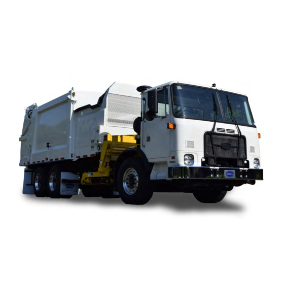
- Page 1 DuraPack Rapid Rail ® ® HIGH-PERFORMANCE AUTOMATED SIDE LOADER SERVICE MANUAL ISSUED MAY 2018 TP1DPRR-SM-0518 © 2017 Heil Environmental...
- Page 2 WARNING IF INCORRECTLY USED, THIS EQUIPMENT CAN CAUSE SEVERE INJURY. THOSE WHO USE AND MAINTAIN THE EQUIPMENT SHOULD BE TRAINED IN ITS PROPER USE, WARNED OF ITS DANGERS, AND SHOULD READ AND FULLY UNDERSTAND THIS ENTIRE MANUAL BEFORE ATTEMPTING TO SET UP, OPERATE, ADJUST OR SERVICE THE EQUIPMENT. KEEP THIS MANUAL FOR FUTURE REFERENCE IMPORTANT SAFETY NOTICE Proper service and repair are important to the safe, reliable operation of Heil Co.’s products.
-
Page 3: Table Of Contents
DuraPack Rapid Rail ® ® TABLE OF CONTENTS General Information Introduction ......................................4 Service/Parts Assistance ......................................5 Hazard Symbols and Definitions ......................................5 Lock-Out/Tag-Out Procedures ......................................9 Storing Refuse in Container ......................................10 Maintenance/Lubrication Information ......................................10 Grease Lubrication Recommendation ......................................10 Oil Lubricant Recommendation ......................................10 Hydraulic Oil Specifications ......................................11 Standard Torque Data for Nuts and Bolts ......................................12... - Page 4 DuraPack Rapid Rail ® ® TABLE OF CONTENTS Welding and Electronic Devices / Electrical Lubricants ......................................70 Repairing Cracked Weld Joints ......................................70 Inspect Proximity Switches ......................................70 Cortex Controller Location ......................................70 Maintenance and Adjustment Body Daily Checklist ......................................72 Body Preventive Maintenance Chart ......................................73 Body Lubrication Guide ......................................75...
- Page 5 DuraPack Rapid Rail ® ® TABLE OF CONTENTS CNG Fuel Cylinder and System Inspections ......................................181 Daily System Inspection ......................................182 Detailed CNG Fuel System Inspection ......................................183 Schematics Packard Connection Kit - 108-4827 ......................................186 Connectors, Plugs, Pins and Accessories for Deutsch Electrical Parts- 108-4815 ......................................188 Deutsch Connection Kit -108-6461-PC ......................................191...
- Page 6 DuraPack Rapid Rail ® ® NOTES Issued November 2017 Copyright 2017, Heil Environmental Printed in U.S.A.
- Page 7 DuraPack Rapid Rail ® ® DuraPack Rapid Rail ® ® HIGH-PERFORMANCE AUTOMATED SIDE LOADER ISSUED MAY 2018 TP1DPRR-SM-0518 Copyright 2017, Heil Environmental Issued November 2017 Printed in U.S.A.
- Page 8 DuraPack Rapid Rail ® ® NOTES Issued November 2017 Copyright 2017, Heil Environmental General Information Printed in U.S.A.
-
Page 9: General Information
DuraPack Rapid Rail ® ® General Information SECTION 1 GENERAL INFORMATION Copyright 2017, Heil Environmental Issued November 2017 General Information Printed in U.S.A. -
Page 10: Introduction
DuraPack Rapid Rail ® ® General Information INTRODUCTION The following sections are a guide for maintenance and service of the Heil unit. The sections cover preventive maintenance, adjustment, and troubleshooting hints. Before performing maintenance, check the work area carefully to find all the hazards present and make sure all necessary safeguards or safety devices are used to protect all persons and equipment involved. -
Page 11: Service/Parts Assistance
DuraPack Rapid Rail ® ® General Information SERVICE/PARTS ASSISTANCE Assistance in troubleshooting repair and service is available by contacting the authorized Heil Dealer in your area. Parts are available at your Heil Dealer or through Heil. Heil personnel are trained to give prompt, professional assistance. ALWAYS give the unit serial number in all correspondence relating to the equipment. - Page 12 DuraPack Rapid Rail ® ® General Information DANGER A tailgate in motion is dangerous. Serious injury or death can occur if a person is struck by a moving tailgate or becomes trapped between the tailgate and the body. Clear the area near the tailgate of all unnecessary people before you lower the tailgate.
- Page 13 DuraPack Rapid Rail ® ® General Information WARNING Raising the body with the tailgate closed can damage the underride bumper. The under ride bumper can hit the ground when the tailgate is not fully raised before you raise the body. Death or serious injury can occur and also cause damage to the unit.
- Page 14 DuraPack Rapid Rail ® ® General Information NOTICE Do not operate the unit or perform repair or maintenance procedures on the unit until you read and understand the instructions in this manual. Failure to do so can result in damage to the unit or other property. If you do not understand a procedure or instruction, tell the owner or the designated person immediately.
-
Page 15: Lock-Out/Tag-Out Procedures
DuraPack Rapid Rail ® ® General Information LOCK-OUT/TAG-OUT PROCEDURES NOTICE Always use your employer’s Lock-Out/Tag-Out procedures. If your employer does not have Lock-Out/Tag-Out procedures, use the procedures that follow. Contact your supervisor or Heil Technical Service if you have any questions about Lock- Out/Tag-Out procedures. -
Page 16: Storing Refuse In Container
DuraPack Rapid Rail ® ® General Information STORING REFUSE IN THE BODY Heil does not recommend storing refuse in the body overnight. The different types of debris and corrosive elements usually collected can cause severe corrosion inside the body decreasing the life of your body. This corrosion can affect unloading and decrease the structural life of the body. -
Page 17: Hydraulic Oil Specifications
DuraPack Rapid Rail ® ® General Information HYDRAULIC OIL SPECIFICATIONS Hydraulic fluid is one of the most important component in hydraulic system. It transmits power, provides lubrication and cooling function and has following features: High viscosity index Long service life Outstanding cold temperature flow properties Fast water separation Excellent anti-wear performance... -
Page 18: Standard Torque Data For Nuts And Bolts
DuraPack Rapid Rail ® ® General Information STANDARD TORQUE DATA FOR NUTS AND BOLTS The following recommended torque data is for use as a general guideline. Recommended torque, in foot pounds, for all Standard Application nuts and bolts provided in the following table. NOTICE Torque specifications on a drawing override torque values in the Standard Torque Data for Nuts and Bolts Table. - Page 19 DuraPack Rapid Rail ® ® General Information STANDARD TORQUE DATA FOR NUTS AND BOLTS TABLE Heil Zinc Plated Heil Heil Thread Heil Plain Dry Fastener Lubricated Deformed Turns per Condition Torque Fastener Lock Nut Bolt Size Nut Type Inch Torque Value Value Torque Value Torque Value...
- Page 20 DuraPack Rapid Rail ® ® General Information STANDARD TORQUE DATA FOR NUTS AND BOLTS TABLE Heil Zinc Plated Heil Heil Thread Heil Plain Dry Fastener Lubricated Deformed Turns per Condition Torque Fastener Lock Nut Bolt Size Nut Type Inch Torque Value Value Torque Value Torque Value...
- Page 21 DuraPack Rapid Rail ® ® General Information STANDARD TORQUE DATA FOR NUTS AND BOLTS TABLE Heil Zinc Plated Heil Heil Thread Heil Plain Dry Fastener Lubricated Deformed Turns per Condition Torque Fastener Lock Nut Bolt Size Nut Type Inch Torque Value Value Torque Value Torque Value...
-
Page 22: Bolt Type Identification Chart
DuraPack Rapid Rail ® ® General Information BOLT TYPE IDENTIFICATION CHART S.A.E. Bolt Head Description Type Grade Marking** No radial lines. 1 or 2 Low or medium carbon steel not heat treated. NOT USED, replace with same grade bolt. Three radial lines. Quenched and tempered medium carbon steel. - Page 23 DuraPack Rapid Rail ® ® General Information TORQUE FOR HYDRAULIC TUBES AND FITTINGS (CONTINUED) 37 DEGREE FLARE (JIC) FITTINGS SET WRENCH TO NOMINAL TUBE OD TORQUE WRENCH SETTING ALTERNATE TORQUE UNITS 1/8" 6.5 ft-lbs. 80 in-lbs. 3/16" 9 ft-lbs. 110 in-lbs. 1/4"...
- Page 24 DuraPack Rapid Rail ® ® General Information TORQUE FOR HYDRAULIC TUBES AND FITTINGS (CONTINUED) FROM SAE J2593 TABLE 7 (STEEL) SET WRENCH TO BOSS (ORB) NOMINAL TUBE OD TORQUE WRENCH SETTING ALTERNATE TORQUE UNITS 3/16" 9 ft-lbs. 110 in-lbs. 1/4" 16.5 ft-lbs.
- Page 25 DuraPack Rapid Rail ® ® General Information TORQUE FOR HYDRAULIC TUBES AND FITTINGS (CONTINUED) Figure 4. Torque for Hydraulic Tubes and Fittings SPLIT- FLANGE (HALF CLAMP) CONNECTORS (CODE 61) SET WRENCH TO NOMINAL TUBE BOLT SIZE BOLT TORQUE [FT- BOLT TORQUE [IN-LBS] ALUMINUM FT- LBS] LBS [IN-LBS]...
- Page 26 DuraPack Rapid Rail ® ® General Information TORQUE FOR HYDRAULIC TUBES AND FITTINGS (CONTINUED) SPLIT- FLANGE (HALF CLAMP) CONNECTORS (CODE 62) SET WRENCH TO NOMINAL BOLT SIZE BOLT TORQUE [FT- BOLT TORQUE [IN-LBS] ALUMINUM FT-LBS [IN- TUBE OD LBS] LBS] 1/2"...
-
Page 27: Cold Weather Warmup Procedure
DuraPack Rapid Rail ® ® General Information COLD WEATHER WARMUP PROCEDURE When ambient air temperature is cold (below 0 degrees F), it is necessary to warm up the unit’s hydraulic oil before you start your daily route operation, check the oil level, or adjust hydraulic pressure settings. The hydraulic oil is sufficiently warmed when the temperature is between 120°... -
Page 28: Proximity Switch Troubleshooting
DuraPack Rapid Rail ® ® General Information PROXIMITY SWITCH TROUBLESHOOTING When one or more of a unit’s functions do not operate properly and there are proximity switches in the circuits of the unit for these functions, refer to the following table as a guide to find the problem(s). NOTICE Heil proximity switches have a Light Emitting Diode (LED) on the switch to indicate that the switch is sensing metal. -
Page 29: Decals On The Unit
DuraPack Rapid Rail ® ® General Information DECALS ON THE UNIT Make sure you can read all hazard and instruction decals. Clean decals if you cannot read the words. See for directions on cleaning decals. Replace any decal that is damaged, missing, or is not readable. When you replace a part that has a decal, make sure a new decal is installed on the new part. - Page 30 DuraPack Rapid Rail ® ® General Information DECAL CARE (CONTINUED) Figure 5. Recommended Technique Figure 6. Incorrect Technique Issued November 2017 Copyright 2017, Heil Environmental General Information Printed in U.S.A.
-
Page 31: Hydraulic Symbols
DuraPack Rapid Rail ® ® General Information HYDRAULIC SYMBOLS Copyright 2017, Heil Environmental Issued November 2017 General Information Printed in U.S.A. - Page 32 DuraPack Rapid Rail ® ® General Information HYDRAULIC SYMBOLS (CONTINUED) Issued November 2017 Copyright 2017, Heil Environmental General Information Printed in U.S.A.
-
Page 33: Electrical Symbols
DuraPack Rapid Rail ® ® General Information ELECTRICAL SYMBOLS Copyright 2017, Heil Environmental Issued November 2017 General Information Printed in U.S.A. - Page 34 DuraPack Rapid Rail ® ® NOTES Issued November 2017 Copyright 2017, Heil Environmental Pumps Printed in U.S.A.
- Page 35 DuraPack Rapid Rail ® ® Pumps SECTION 2 PUMPS Copyright 2017, Heil Environmental Issued November 2017 Pumps Printed in U.S.A.
-
Page 36: Tandem Vane Pump With Priority Valve
DuraPack Rapid Rail ® ® Pumps TANDEM VANE PUMP WITH PRIORITY VALVE Figure 7. Front Mount Pump Kit Issued November 2017 Copyright 2017, Heil Environmental Pumps Printed in U.S.A. - Page 37 DuraPack Rapid Rail ® ® Pumps TANDEM VANE PUMP WITH PRIORITY VALVE (CONTINUED) Figure 8. Pump Hydraulic Schematic Copyright 2017, Heil Environmental Issued November 2017 Pumps Printed in U.S.A.
- Page 38 DuraPack Rapid Rail ® ® NOTES Issued November 2017 Copyright 2017, Heil Environmental Lift Arm Printed in U.S.A.
-
Page 39: Lift Arm
DuraPack Rapid Rail ® ® Lift Arm SECTION 3 LIFT ARM Copyright 2017, Heil Environmental Issued November 2017 Lift Arm Printed in U.S.A. -
Page 40: Specifications
DuraPack Rapid Rail ® ® Lift Arm LIFT SPECIFICATIONS Valve Pressure Settings Pressures and Times Arm Valve Relief 2200 PSI Loader In/Out Relief 2350/1200 PSI Release 1100 PSI Body Valve Relief 2500 PSI Cycle Times Loader Cycle 7-9 seconds Issued November 2017 Copyright 2017, Heil Environmental Lift Arm Printed in U.S.A. -
Page 41: Lift Arm Nomenclature
DuraPack Rapid Rail ® ® Lift Arm LIFT ARM NOMENCLATURE Refer to the Parts Manual Section 2 for Lift Arm part numbers. Figure 9. Lift Arm Nomenclature Copyright 2017, Heil Environmental Issued November 2017 Lift Arm Printed in U.S.A. - Page 42 DuraPack Rapid Rail ® ® Lift Arm LIFT ARM NOMENCLATURE (CONTINUED) Issued November 2017 Copyright 2017, Heil Environmental Lift Arm Printed in U.S.A.
- Page 43 DuraPack Rapid Rail ® ® Lift Arm LIFT ARM NOMENCLATURE (CONTINUED) Copyright 2017, Heil Environmental Issued November 2017 Lift Arm Printed in U.S.A.
- Page 44 DuraPack Rapid Rail ® ® Lift Arm LIFT ARM NOMENCLATURE (CONTINUED) Issued November 2017 Copyright 2017, Heil Environmental Lift Arm Printed in U.S.A.
- Page 45 DuraPack Rapid Rail ® ® Lift Arm LIFT ARM NOMENCLATURE (CONTINUED) Copyright 2017, Heil Environmental Issued November 2017 Lift Arm Printed in U.S.A.
- Page 46 DuraPack Rapid Rail ® ® Lift Arm LIFT ARM NOMENCLATURE (CONTINUED) Issued November 2017 Copyright 2017, Heil Environmental Lift Arm Printed in U.S.A.
-
Page 47: Lift Arm Lubrication Guide
DuraPack Rapid Rail ® ® Lift Arm LIFT ARM LUBRICATION GUIDE NOTICE Clean all fittings before applying grease and always pump enough grease into the joint to remove the old grease. Wipe off excess. Figure 10. Lift Arm Lubrication Guide Copyright 2017, Heil Environmental Issued November 2017 Lift Arm... -
Page 48: Durapack Rapid Rail Lift Cylinder Sensors Calibration
DuraPack Rapid Rail ® ® Lift Arm DPF RR cylinder sensors calibration should be performed on an annual basis ONLY by authorized service personnel. This procedure requires a password to place the unit in Calibration Mode. This password can be provided to authorized service personnel by contacting Heil Technical Services at 866-310-4345. -
Page 49: Carriage Assembly Roller Bearing Torque Check
DuraPack Rapid Rail ® ® Lift Arm CARRIAGE ASSEMBLY ROLLER BEARING TORQUE CHECK There are eighteen (18) bearings in the carriage assembly. If the torque is less than specified, the life of the bearing is much shorter. If the torque is greater than specified, the bearings will freeze and fail prematurely. NOTICE It is critical that you routinely check the torque of the following roller bearings on the loader’s carriage assembly. -
Page 50: Universal Belt And Tri-Cuff Grabber Adjustments
DuraPack Rapid Rail ® ® Lift Arm UNIVERSAL BELT AND TRI-CUFF GRABBER ADJUSTMENTS A. 60-90 Gallon Belt Grabbers Adjust the grabber belt length so the distance between the roller on the inner arm and the outside roller is 30” (+/- 1”). See illustration below. - Page 51 DuraPack Rapid Rail ® ® Lift Arm UNIVERSAL BELT AND TRI-CUFF GRABBER ADJUSTMENTS (CONTINUED) B. 90-300 Gallon Belt Grabbers Adjust the grabber belt length so the distance between the inner arm and the outside roller is approximate 30” (+/- 1”) to obtain a firm grip for smaller containers.
- Page 52 DuraPack Rapid Rail ® ® Lift Arm UNIVERSAL BELT AND TRI-CUFF GRABBER ADJUSTMENTS (CONTINUED) C. 30-110 Gallon Tri-Cuff Belt Grabbers Adjust the grabber belt length so the distance between the roller on the inner arm and the outside roller is 30” (+/- 1”). See illustration below.
-
Page 53: Body And Tailgate
DuraPack Rapid Rail ® ® BODY AND TAILGATE SECTION 4 BODY AND TAILGATE Copyright 2017, Heil Environmental Issued November 2017 Body and Tailgate Printed in U.S.A. -
Page 54: Body Specifications
DuraPack Rapid Rail ® ® BODY AND TAILGATE BODY SPECIFICATIONS All pressures are +/-100 PSI at operating temperature. See Lift Control Valve Pressure Adjustments and Relief Valve Adjustment in this section for valve adjustment procedures. Pump Type ..................Operate–In-Gear-At-Idle, Front Mount, Tandem Vane Max Operating Pressure .......................... -
Page 55: Body Nomenclature
DuraPack Rapid Rail ® ® BODY AND TAILGATE BODY NOMENCLATURE Shown below are some of the features of the body. Copyright 2017, Heil Environmental Issued November 2017 Body and Tailgate Printed in U.S.A. -
Page 56: Tailgate Nomenclature
DuraPack Rapid Rail ® ® BODY AND TAILGATE TAILGATE NOMECLATURE Shown below are some of the features of the tailgate. Issued November 2017 Copyright 2017, Heil Environmental Body and Tailgate Printed in U.S.A. -
Page 57: Optional Flat Tailgate Nomenclature
DuraPack Rapid Rail ® ® BODY AND TAILGATE OPTIONAL FLAT TAILGATE NOMENCLATURE The optional Flat Tailgate weighs about the same as the standard bubble tailgate. This tailgate is not designed to save weight but to transfer more weight to the front axle to achieve a more desirable weight distribution. Shown below are some of the features of the optional Flat Tailgate. -
Page 58: Propping The Body Of A Service Hoist Unit
DuraPack Rapid Rail ® ® BODY AND TAILGATE PROPPING THE BODY OF A SERVICE HOIST UNIT Operators MUST KNOW how to SAFELY prop up the unit’s body. You may need to prop the body up when you clean the inside of the body or for maintenance or repair procedures. Observe and obey the following DANGER and WARNING notices while you prop the body with the factory body props. - Page 59 DuraPack Rapid Rail ® ® BODY AND TAILGATE PROPPING THE BODY OF A SERVICE HOIST UNIT (CONTINUED) The factory-supplied body props are located on both sides under the body and forward of the rear wheels. Refer to the figure to the right and carefully follow the body propping procedures below. Follow These Steps to Raise the Body: 1.
- Page 60 DuraPack Rapid Rail ® ® BODY AND TAILGATE PROPPING THE BODY OF A SERVICE HOIST UNIT (CONTINUED) 12.NEVER open the override valve when the body is elevated. 13.Perform the maintenance or service procedures. Figure 15. Factory Body Props Issued November 2017 Copyright 2017, Heil Environmental Body and Tailgate Printed in U.S.A.
-
Page 61: Propping The Body Of A Service Lift (Serviceable Eject) Unit
DuraPack Rapid Rail ® ® BODY AND TAILGATE PROPPING THE BODY OF A SERVICE LIFT (SERVICEABLE EJECT) UNIT Operators MUST KNOW how to SAFELY prop up the unit’s body. You may need to prop the body up when you clean the inside of the body or for maintenance or repair procedures. - Page 62 DuraPack Rapid Rail ® ® BODY AND TAILGATE PROPPING THE BODY OF A SERVICE LIFT (SERVICEABLE EJECT) UNIT (CONTINUED) The factory-supplied body props are located on both sides under the body and forward of the rear wheels. Refer to the figure to the right and carefully follow the body propping procedures below.
- Page 63 DuraPack Rapid Rail ® ® BODY AND TAILGATE PROPPING THE BODY OF A SERVICE LIFT (SERVICEABLE EJECT) UNIT (CONTINUED) 8. Using the lifting device, slowly lift the body in a controlled manner high enough to lower the factory body props. See the figure below.
- Page 64 DuraPack Rapid Rail ® ® BODY AND TAILGATE PROPPING THE BODY OF A SERVICE LIFT (SERVICEABLE EJECT) UNIT (CONTINUED) 10.Using the lifting device, slowly lower the body in a controlled manner until the body is resting on the prop stands. See the figure below.
-
Page 65: Serial Plate Locations
DuraPack Rapid Rail ® ® BODY AND TAILGATE SERIAL PLATE LOCATIONS You determine the sides of the unit by facing the direction of forward travel. The left side is the “streetside” and the right side is the “curbside”. The figure below shows the location of the serial plate on the streetside of the unit’s body. See the next page for a description of the information that is on the serial plate. -
Page 66: Body Sump Doors
DuraPack Rapid Rail ® ® BODY AND TAILGATE BODY SUMP DOORS Sump doors are located on the front corner of each side of the body. Open the doors when cleaning out the sump area. A cleaning tool is provided with each unit. Close the doors at all times except when cleaning. Cleaning should occur daily. See the figure below. -
Page 67: Side Access Doors
DuraPack Rapid Rail ® ® BODY AND TAILGATE SIDE ACCESS DOORS Hinged access doors are located on each side of the unit. See the figure below. WARNING Make sure the unit is in the Lock-Out/Tag-Out mode when you do maintenance or service procedures, when you go in the hopper, enter the side access doors, or climb on the body or equipment. -
Page 68: Tailgate Support Props
DuraPack Rapid Rail ® ® BODY AND TAILGATE TAILGATE SUPPORT PROPS Two support props are on the unit and must be used whenever the tailgate is opened for service or maintenance. Both props must be used. DANGER A tailgate in motion is dangerous. Serious injury or death may occur if a person is struck by a moving tailgate or becomes trapped between the tailgate and the body. - Page 69 DuraPack Rapid Rail ® ® BODY AND TAILGATE TAILGATE SUPPORT PROPS (CONTINUED) Copyright 2017, Heil Environmental Issued November 2017 Body and Tailgate Printed in U.S.A.
-
Page 70: Main Control And Regenerative Valves
DuraPack Rapid Rail ® ® BODY AND TAILGATE MAIN CONTROL AND REGENERATIVE VALVES The image below shows the regenerative valve and body valve locations on the street side of the unit. Issued November 2017 Copyright 2017, Heil Environmental Body and Tailgate Printed in U.S.A. -
Page 71: Regenerative Valve
DuraPack Rapid Rail ® ® BODY AND TAILGATE REGENERATIVE VALVE Part time regenerative valve during packer extend. Full time dump valve during packer retract. Figure 23. Regenerative Valve Copyright 2017, Heil Environmental Issued November 2017 Body and Tailgate Printed in U.S.A. -
Page 72: Regenerative Valve Troubleshooting Guide
DuraPack Rapid Rail ® ® BODY AND TAILGATE REGENERATIVE VALVE TROUBLESHOOTING GUIDE Issued November 2017 Copyright 2017, Heil Environmental Body and Tailgate Printed in U.S.A. - Page 73 DuraPack Rapid Rail ® ® BODY AND TAILGATE REGENERATIVE VALVE TROUBLESHOOTING GUIDE (CONTINUED) Copyright 2017, Heil Environmental Issued November 2017 Body and Tailgate Printed in U.S.A.
- Page 74 DuraPack Rapid Rail ® ® BODY AND TAILGATE REGENERATIVE VALVE TROUBLESHOOTING GUIDE (CONTINUED) Issued November 2017 Copyright 2017, Heil Environmental Body and Tailgate Printed in U.S.A.
-
Page 75: Optional Sliding Top Door
DuraPack Rapid Rail ® ® BODY AND TAILGATE OPTIONAL SLIDING TOP DOOR A sliding top door is located on top of the unit to cover the hopper area when traveling to help eliminate trash from blowing out of the hopper area. Shown below is the top door and related parts. Figure 24. -
Page 76: Welding And Electronic Devices / Electrical Lubricants
DuraPack Rapid Rail ® ® BODY AND TAILGATE WELDING AND ELECTRONIC DEVICES / ELECTRICAL LUBRICANTS proximity switches complete the following procedures. WARNING Never weld on a compressed natural gas vehicle unless the compressed natural gas fuel system has been purged with inert gas. -
Page 77: Maintenance And Adjustment
DuraPack Rapid Rail ® ® Maintenance and Adjustment SECTION 5 MAINTENANCE AND ADJUSTMENT Copyright 2017, Heil Environmental Issued November 2017 Maintenance and Adjustment Printed in U.S.A. -
Page 78: Body Daily Checklist
DuraPack Rapid Rail ® ® Maintenance and Adjustment BODY DAILY CHECKLIST Make sure you perform a daily check of the unit. Refer to the Operator’s Manual for the Daily Checklist. Many checks in the Daily Checklist are maintenance related, such as checking tire pressures and hoses for wear and damage. DAILY CHECKLIST MAINTENANCE ITEMS ITEM REQUIRED ACTION... -
Page 79: Body Preventive Maintenance Chart
DuraPack Rapid Rail ® ® Maintenance and Adjustment BODY PREVENTIVE MAINTENANCE CHART Preventive maintenance must be performed to ensure the safe and reliable operation of your unit. Use the chart below as a guideline for when essential items should checked and serviced. Severe use or adverse conditions may require more frequent maintenance. - Page 80 DuraPack Rapid Rail ® ® Maintenance and Adjustment BODY PREVENTIVE MAINTENANCE CHART *HOURS OF OPERATION COMPONENT/SYSTEM 1000 2000 CHECK/SERVICE Lubricate as shown on Body Lube Grease Fittings Chart. Inspect body undercoating and repair Body Undercoating as necessary. For Front Loaders Only, each of the Fork Bearing Block Bolts (Front four fork bearing block bolt torques Loaders Only)
-
Page 81: Body Lubrication Guide
DuraPack Rapid Rail ® ® Maintenance and Adjustment BODY LUBRICATION GUIDE Clean fittings before applying grease and always pump enough grease into joint to remove the old grease. Wipe off excess grease. Lubricate moveable mechanical parts without fittings every 60 days with non-detergent engine oil. Also see Lift Arm Lubrication Guide REF NO. -
Page 82: Pack/Eject Cylinders Maintenance
DuraPack Rapid Rail ® ® Maintenance and Adjustment PACK/EJECT CYLINDERS MAINTENANCE Heil Environmental recommends completing the following tasks to make sure the pack/eject cylinders are working properly and not damaged. WARNING Make sure that the unit is in Lock-Out/Tag-Out mode before you perform maintenance/service procedures, or when you enter or climb on the hopper/body/related assemblies. -
Page 83: Cold Weather Warmup Procedure
DuraPack Rapid Rail ® ® Maintenance and Adjustment COLD WEATHER WARM-UP PROCEDURE When ambient air temperature is cold (below 0 degrees F), it is necessary to warm up the unit’s hydraulic oil before you start your daily route operation or to check the oil level. The hydraulic oil is sufficiently warmed when the temperature is between 120°... -
Page 84: Preparing The Unit To Check The Oil Level
DuraPack Rapid Rail ® ® Maintenance and Adjustment PREPARING THE UNIT TO CHECK THE OIL LEVEL Before checking the oil level or adding oil, make sure the unit is in the following position with all cylinders collapsed: Truck – on level ground Tailgate and Body –... -
Page 85: Check Oil Level
DuraPack Rapid Rail ® ® Maintenance and Adjustment CHECK OIL LEVEL Check the hydraulic oil level (after warning up the oil) daily or every eight (8) hours, whichever comes first. Fill as necessary. Important: Contamination is a hydraulic system’s worst enemy. Do not let dirt enter the system. Use a clean rag and remove dirt or other contamination around any system component before you disconnect or remove it. -
Page 86: Drain And Clean The Hydraulic Oil Tank
DuraPack Rapid Rail ® ® Maintenance and Adjustment DRAIN AND CLEAN THE HYDRAULIC OIL TANK Change the hydraulic oil at least annually or every 2000 hours of operating time, whichever comes first. Remember that almost all hydraulic system malfunctions can be traced to dirt in the fluid. When working with the hydraulic system, the hands, tools, working area and parts must be as clean as possible. -
Page 87: Purge The Hydraulic System
DuraPack Rapid Rail ® ® Maintenance and Adjustment DRAIN AND CLEAN THE HYDRAULIC OIL TANK (CONTINUED) NOTICE Before filling the tank be sure the funnel is clean and 200 mesh (or finer) screen is used to strain the hydraulic oil. 13.Fill tank with recommended oil, checking the sight gauge as you fill. -
Page 88: Pressure Adjustment Settings
DuraPack Rapid Rail ® ® Maintenance and Adjustment PRESSURE ADJUSTMENT SETTINGS A. Unit Preparation Follow these unit preparation steps prior to making any pressure adjustments listed in this section. 1. Make sure area around unit is clear to enable arm and fork operation. 2. - Page 89 DuraPack Rapid Rail ® ® Maintenance and Adjustment PRESSURE ADJUSTMENT SETTINGS (CONTINUED) C. Pressures HYDRAULIC PRESSURES ARM VALVE RELIEF ARM VALVE ARM IN OUT PORT RELIEF RELEASE RELIEF RELIEF 2200 PSI 2500 PSI 2350 PSI 1200 PSI 1100 PSI Notes: 1.
-
Page 90: Regen Dump Valve (031-6227) Troubleshooting Guide
DuraPack Rapid Rail ® ® Maintenance and Adjustment Regen Dump Valve (031-6227) Troubleshooting Guide Issued November 2017 Copyright 2017, Heil Environmental Maintenance and Adjustment Printed in U.S.A. - Page 91 DuraPack Rapid Rail ® ® Maintenance and Adjustment Regen Dump Valve (031-6227) Troubleshooting Guide (Continued) Copyright 2017, Heil Environmental Issued November 2017 Maintenance and Adjustment Printed in U.S.A.
- Page 92 DuraPack Rapid Rail ® ® Maintenance and Adjustment Regen Dump Valve (031-6227) Troubleshooting Guide (Continued) Issued November 2017 Copyright 2017, Heil Environmental Maintenance and Adjustment Printed in U.S.A.
-
Page 93: Cracked Weld Joints
DuraPack Rapid Rail ® ® Maintenance and Adjustment REPAIRING CRACKED WELD JOINTS Repair all cracked weld joints immediately after finding cracked weld joints. If you are unsure of the proper repair procedure, call Heil Technical Services at 866-310-4345. OIL LUBRICANT RECOMMENDATION Use only non-detergent engine oil to lubricate all moveable mechanical parts not furnished with grease fittings. - Page 94 DuraPack Rapid Rail ® ® NOTES Issued November 2017 Copyright 2017, Heil Environmental Body Controller Hardware Printed in U.S.A.
- Page 95 DuraPack Rapid Rail ® ® Body Controller Hardware SECTION 6 BODY CONTROLLER HARDWARE Copyright 2017, Heil Environmental Issued November 2017 Body Controller Hardware Printed in U.S.A.
-
Page 96: Body Controller Hardware
DuraPack Rapid Rail ® ® Body Controller Hardware NOTES Issued November 2017 Copyright 2017, Heil Environmental Body Controller Hardware Printed in U.S.A. - Page 97 DuraPack Rapid Rail ® ® Body Controller Hardware 80 I/O ASSEMBLY Copyright 2017, Heil Environmental Issued November 2017 Body Controller Hardware Printed in U.S.A.
- Page 98 DuraPack Rapid Rail ® ® Body Controller Hardware Figure 28. 80 I/O Cortex Controller Hardware Issued November 2017 Copyright 2017, Heil Environmental Body Controller Hardware Printed in U.S.A.
-
Page 99: Pin Number Diagram
DuraPack Rapid Rail ® ® Body Controller Hardware plastic for pin numbers 1 and 19 (top row left to top row right), 20 and 37 (middle row left to middle row right), and 38 and 55 (bottom row left and bottom row right). Figure 29. - Page 100 DuraPack Rapid Rail ® ® Body Controller Hardware Follow these steps to assembly the Cortex Controller Cable. A. Cable and Controller Parts Identification See the figure below to identify the 55-Pole Cable Connector parts. Figure 30. Cable Controller Plastic Male Hinge Pins and Controller Female Slot Connectors Issued November 2017 Copyright 2017, Heil Environmental Body Controller Hardware...
- Page 101 DuraPack Rapid Rail ® ® Body Controller Hardware B. Female Controller Connector Close-Up View See the figure below to identify the controller female connector. Figure 31. Female Controller Connector Slots Copyright 2017, Heil Environmental Issued November 2017 Body Controller Hardware Printed in U.S.A.
- Page 102 DuraPack Rapid Rail ® ® Body Controller Hardware C.Connecting the 55-Pole Cable Connector Refer to the figure below and then slide cable male connectors into controller female connectors. Figure 32. Cable Connector Pivoting on Controller Issued November 2017 Copyright 2017, Heil Environmental Body Controller Hardware Printed in U.S.A.
- Page 103 DuraPack Rapid Rail ® ® Body Controller Hardware D.Pivot Cable Connector and Latch 1. While keeping left side of cable connector seated, carefully pivot cable connector until flush with controller. See the figure below. Figure 33. Slowly Press Down While Keeping Left Cable Connector Pivot Point in Place 2.
- Page 104 DuraPack Rapid Rail ® ® Body Controller Hardware See the figures below for front and rear photos and rear illustration. Contact Heil for re-programming of the display. Figure 35. Insight Display Front Photo Figure 36. Insight Display Rear Photo (1) M12 connector (2) M52 thread for fixing nut (3) Locating pins Figure 37.
- Page 105 DuraPack Rapid Rail ® ® Body Controller Hardware See the figure below for a rear view of the display with cable connected. Figure 38. Rear View of Display with Cable Connected Contact Heil Environmental for re-programming of the Cortex Controller. DESCRIPTION PART NUMBER Cortex Controller RS232 Cable...
- Page 106 DuraPack Rapid Rail ® ® NOTES Issued November 2017 Copyright 2017, Heil Environmental Body Controller Software Printed in U.S.A.
- Page 107 DuraPack Rapid Rail ® ® Body Controller Software SECTION 7 BODY CONTROLLER SOFTWARE Copyright 2017, Heil Environmental Issued November 2017 Body Controller Software Printed in U.S.A.
-
Page 108: Body Controller Software
DuraPack Rapid Rail ® ® Body Controller Software DuraPack Rapid Rail ® ® Section 1: CORTEX32 Controller Hardware 1.01: CORTEX32 Controller Indicator Lights The CORTEX32 Controller is an Extended Controller consisting of 80 Inputs / Outputs, which operates with a voltage ranging from (8 to 32) Volt DC. - Page 109 DuraPack Rapid Rail ® ® Body Controller Software Figure: Pulse Width Modulation (PWM) Output Waveforms 1.04: Communication Ports There are 4-CAN and 1-RS-232 communication port in the 80 I/O CORTEX32 Controlle r which will be utilized for the programming and communication purposes. The Serial port (RS-232) in the ST side will be utilized to download user programs via CORTEX Download tool (Downloader 32) and CAN ports in the ST side for communication between Controller and field devices.
- Page 110 DuraPack Rapid Rail ® ® Body Controller Software 1.06: CORTEX32 Controller - Connector Pin Details The table below gives connection details between CORTEX32 Controller Input/output and Connector Pins. PROGRAM: 109-0301 REVISION: 20151109 CONNECTOR DPF RAPID RAIL PIN-OUT ADDRESS DETAILS IN-CAB INPUT FUNCTIONS P1-24 A01 SYSTEM POWER SWITCH %IX0.8...
- Page 111 DuraPack Rapid Rail ® ® Body Controller Software PROGRAM: 109-0301 REVISION: 20151109 CONNECTOR DPF RAPID RAIL PIN-OUT ADDRESS DETAILS F02 LIFT IN OCC PWM %QX0.5 P1-13 F03 LIFT DOWN OCC PWM %QX0.6 P1-12 F04 LIFT UP OCC PWM %QX0.7 P1-11 F05 LIFT GRAB OCC PWM %QX0.12 P1-6...
- Page 112 DuraPack Rapid Rail ® ® Body Controller Software PROGRAM: 109-0301 REVISION: 20151109 CONNECTOR DPF RAPID RAIL PIN-OUT ADDRESS DETAILS IW3) %IX0.12 P1-22 K03 OIL TANK TEMPERATURE (%IW14) %IX0.3 (% P1-35 K04 LIFT CYLINDER UP/DOWN IW5) %IX0.4 (% P1-53 K05 LIFT CYLINDER IN/OUT IW6) %IX0.5 (% P1-34...
- Page 113 DuraPack Rapid Rail ® ® Body Controller Software PROGRAM: 109-0301 REVISION: 20151109 CONNECTOR DPF RAPID RAIL PIN-OUT ADDRESS DETAILS L11 LIFT UP PUSH BUTTON LIFT BANK L12 LIFT OUT PUSH BUTTON LIFT BANK L13 LIFT IN PUSH BUTTON LIFT BANK L14 LIFT DUMP PUSH BUTTON LIFT BANK L15 LIFT UNDUMP PUSH BUTTON...
- Page 114 DuraPack Rapid Rail ® ® Body Controller Software Section 2: J1939 Details The Engine information is directly read through the SAE J1939 standard. SAE J1939 is the vehicle bus standard used for communication and diagnostics among vehicle components, like heavy duty truck industry.
- Page 115 DuraPack Rapid Rail ® ® Body Controller Software Section 4: I/O Functions The following sheets detail the functionality of the Input and Output functions provided through the CORTEX32 Controller. Note: Status of all the Inputs / Outputs can be monitored using the Insight In-Cab display. Refer section 5.05 for more details about Diagnostic display options and INSIGHT display.
- Page 116 DuraPack Rapid Rail ® ® Body Controller Software A04 Input Function – Turn Signals (In Cab Input %IX0.13) This circuit monitors the status of the Turn Signal circuit. Left and Right turn signals are Dioded together for this input. This circuit is used for enabling and disabling Strobe circuit for some customers.
- Page 117 DuraPack Rapid Rail ® ® Body Controller Software Input Device Status I/O Address Status Scale Alarm-1 Activated %IX128.0 A08 Input Function Scale Alarm-2 (In Cab Input % IX128.2) This circuit monitors the ON/OFF status of the Scale Alarm-2 condition. This Scale Input goes Low (OFF) during overweight condition.
- Page 118 DuraPack Rapid Rail ® ® Body Controller Software Condition Modifiable Parameters Default Setting None Conditions Necessary to activate the circuit: Condition Function or Component Status I/O Address Status Tailgate Closed Prox. Switch Deactivated %QX128.10 Note: Condition ‘A’ true will activate the Warble Alarm output. 4.03: Standard Body Input Functions C01 Input Function –...
- Page 119 DuraPack Rapid Rail ® ® Body Controller Software C04 Input Function -- Tailgate Closed Proximity Switch (Body Input % IX128.10) This circuit monitors the ON/OFF status of the Tailgate Closed Proximity Switch. The input is ON when the Tailgate is closed.
- Page 120 DuraPack Rapid Rail ® ® Body Controller Software Condition Function or Component Status I/O Address Status Packer Extend Activated %QX128.16 System Power Switch Activated %IX0.8 Lift Up Active Deactivated Lift Down Active Deactivated Lift In Active Deactivated Lift Out Active Deactivated Lift Dump Active Deactivated...
- Page 121 DuraPack Rapid Rail ® ® Body Controller Software Note: This signal is energized using a CAN based control by energizing the Tailgate Raise push button, either from Street side or from the Curb side of a dual control panel unit. With Conditions (B AND C AND D (if configured)) true, function ‘A’...
- Page 122 DuraPack Rapid Rail ® ® Body Controller Software Conditions necessary to activate the circuit: Condition Function or Component Status I/O Address Status Tailgate Un Lock Push Button Activated Panel Select Switch Activated %IX0.11 or Tailgate Down Activated %QX0.9 Road Speed OK Activated ON (see Note below) Body Pump...
- Page 123 DuraPack Rapid Rail ® ® Body Controller Software Condition Function or Component Status I/O Address Status Packer Retract Push Button Deactivated Joystick Packer Pressure switch Deactivated %IX128.21 System Power Switch Activated %IX0.8 Packer Travel position switch Deactivated Packer Full Extend Prox. Switch Deactivated %IX128.14 Tailgate Closed Prox.
- Page 124 DuraPack Rapid Rail ® ® Body Controller Software Condition Modifiable Parameters Default Setting None Function Logic: Input Device Status I/O Address Status Grabber Full Open Proximity Switch Activated %IX128.11 E02 Input Function – Grabber Closed Pressure Switch (Body Input % IX128.13) This circuit monitors the ON/OFF status of the Grabber Closed pressure switch.
- Page 125 DuraPack Rapid Rail ® ® Body Controller Software operated. Condition Modifiable Parameters Default Setting None Conditions necessary to activate the circuit: Condition Function or Component Status I/O Address Status Co-ordinated mode Switch Activated Lift Pump On Activated %QX128.0 Sensor Failure Deactivated N/A Manual Lift In Activated...
- Page 126 DuraPack Rapid Rail ® ® Body Controller Software F04 Output Function – Lift Up OCC PWM control (Body Output %QX0.07) This output function controls the Lift Up OCC PWM control output circuit. The Lift Up OCC PWM control circuit either with the Auto Lift signal (fixed speed) or with the Manual lift signal (variable speed) will control the speed of Lift Up when operated.
- Page 127 DuraPack Rapid Rail ® ® Body Controller Software F06 Output Function – Lift Release OCC PWM control (Body Output %QX0.13) This output function controls the Lift Release OCC PWM control output circuit. The Lift Release OCC PWM control circuit, either with the Auto Lift signal (fixed speed) or with the Manual lift signal (variable speed), will control the speed of Lift Release when operated.
- Page 128 DuraPack Rapid Rail ® ® Body Controller Software UnDump when operated. Condition Modifiable Parameters Default Setting None Conditions necessary to activate the circuit: Condition Function or Component Status I/O Address Status Co-ordinated mode Switch Activated Lift Pump On Activated %QX128.0 Sensor Failure Deactivated N/A Manual UnDump...
- Page 129 DuraPack Rapid Rail ® ® Body Controller Software Conditions Necessary to activate the circuit: Condition Function or Status I/O Address Status Component NOT USED. FUTURE EXPANSION G02 Output Function – Force Neutral Signal (In Cab Output %QX128.22) This output function controls the Force Neutral signal transmitted to the vehicles engine. Future expansion. Condition Modifiable Parameters Default Setting None...
- Page 130 DuraPack Rapid Rail ® ® Body Controller Software Condition Modifiable Parameters Default Setting None Function Logic: Input Device Status I/O Address Status Body HP Filter Pressure Switch-2 Activated %IX128.6 H04 Input Function - Tailgate Locked Proximity Switch (Body Input %IX128.8) This circuit monitors the ON/OFF status of the Tailgate Locked Proximity Switch i.e.
- Page 131 DuraPack Rapid Rail ® ® Body Controller Software None Function Logic: Input Device Status I/O Address Status Tailgate Throttle Advance Switch Activated %IX128.17 Future Expansion H08 Input Function – Tailgate Buzzer Switch (Body Input %IX128.18) This circuit monitors the ON/OFF status of the Tailgate Throttle Advance Switch. Future Expansion. Condition Modifiable Parameters Default Setting None...
- Page 132 DuraPack Rapid Rail ® ® Body Controller Software None Conditions Necessary to activate the circuit Condition Function or Status I/O Address Status Component NOT USED. FUTURE EXPANSION J03 Output Function - Top Door Close / Hopper Cover Close (Body Output %QX128.3) This output function controls the Top Door Close/ Hopper Cover Close output.
- Page 133 DuraPack Rapid Rail ® ® Body Controller Software Body Lower Push Button Activated Panel Select Switch Activated %IX0.11 Road Speed OK Activated ON (see Note below) Body Pump Activated %QX128.1 Note: This signal is energized using a CAN based control by energizing the Body Lower push button, either from Street side or from the Curb side of a dual control panel unit.
- Page 134 DuraPack Rapid Rail ® ® Body Controller Software Condition Modifiable Parameters Default Setting None Conditions Necessary to activate the circuit: Condition Function or Status I/O Address Status Component Lift Light Switch Activated Panel Select Switch Activated %IX0.11 Note: With condition (A) true, the Lift Flood Light output will be activated. J09 Output Function –...
- Page 135 DuraPack Rapid Rail ® ® Body Controller Software J11 Output Function – Strobe Light 2 (In Cab Output %QX128.15) This circuit operates the Strobe light-2 circuit. Condition Modifiable Parameters Default Setting None Conditions Necessary to activate the circuit Condition Function or Status I/O Address Status...
- Page 136 DuraPack Rapid Rail ® ® Body Controller Software Function Logic: Input Device Status I/O Address Status Oil Temperature Analog %IX0.12 - %IW14 RESISTIVE K04 Input Function – Lift Cylinder Up/ Down Position (Analog Input %IX0.3 - %IW5) This circuit measures the position of Lift Cylinder Up/Down Cylinder. Condition Modifiable Parameters Default Setting None...
- Page 137 DuraPack Rapid Rail ® ® Body Controller Software Function Logic: Input Device Status I/O Address Status Hydraulic Pump Enable Push Button Activated ON (CAN Control) L02 Input Function -- Packer Extend Push Button (CAN - In Cab Input) This CAN control is used to turn ON/OFF the Packer Extend control either from Street side or from the Curb side of a dual control panel unit.
- Page 138 DuraPack Rapid Rail ® ® Body Controller Software Function Logic: Input Device Status I/O Address Status Feather Mode Switch Activated ON (CAN Control) L06 Input Function – Tailgate Raise Enable Switch (CAN - In Cab Input) This CAN control is used to raise the Tailgate, either from Street side or from the Curb side of a dual control panel unit Condition Modifiable Parameters Default Setting None...
- Page 139 DuraPack Rapid Rail ® ® Body Controller Software Tailgate Unlock Enable switch Activated ON (CAN Control) L10 Input Function – Lift Down Push Button (CAN - In Cab Input) This CAN control button is used to turn ON the Lift Down solenoid from the auxiliary switch bank. Condition Modifiable Parameters Default Setting None...
- Page 140 DuraPack Rapid Rail ® ® Body Controller Software L14 Input Function – Lift Dump Push Button (CAN - In Cab Input) This CAN control button is used to turn ON the Lift Dump solenoid from the auxiliary switch bank. Condition Modifiable Parameters Default Setting None Function Logic:...
- Page 141 DuraPack Rapid Rail ® ® Body Controller Software 4.12: CAN JOYSTICK CONTROLS INPUT FUNCTIONS The Python Style and Rapid Rail CAN Joystick controls can be operated either form Street side or from Curb side. The Python Style CAN Joystick has 5 Push buttons on the handle that can control Pump, Grabbers, and Packer Extend / Retract functions.
- Page 142 DuraPack Rapid Rail ® ® Body Controller Software a. Moving and holding the Joystick to Left (X-axis in Negative direction) performs the Lift Undump operation. Releasing the joystick stops the movement of the lift. The movement of this function is proportional to the % travel of the joystick.
- Page 143 DuraPack Rapid Rail ® ® Body Controller Software (RAPIDRAIL JOYSTICK MODE) The Rapid Rail Style Joystick has a rocker switch on the top of the joystick. When the left rocker button is pressed, the Lift In operation is performed. Condition Modifiable Parameters Default Setting None Function Logic:...
- Page 144 DuraPack Rapid Rail ® ® Body Controller Software M08 Input Function – Joystick – Packer Retract button (Yellow) (CAN – Cab Input) The Python Style Joystick has 5 push buttons on the handle to control various operations. The Yellow push button on the Joystick is used for Packer Retract operation. Depress and release button and the Packer panel will retract to front of the body.
- Page 145 DuraPack Rapid Rail ® ® Body Controller Software Packer Travel Position Switch Activated ON (CAN Control) N04 Input Function – Top Door Open Switch (CAN - In Cab Input) This CAN control is used to open the Top Door either from Street side or from the Curb side of a dual control panel unit. Condition Modifiable Parameters Default Setting None...
- Page 146 DuraPack Rapid Rail ® ® Body Controller Software N08 Input Function – Auxiliary Light Enable Switch (CAN - In Cab Input) This CAN control is used to turn ON/OFF the Auxiliary Backup Light Circuit either from Street side or from the Curb side of a dual control panel unit.
- Page 147 DuraPack Rapid Rail ® ® Body Controller Software Section 5: Special Features 5.01: Auto Pack Mode Auto Pack is a standard feature in CORTEX32 products. The Packer defaults to Auto Mode at all times, unless configured to manual pack. While in Auto Pack the Packer will complete its cycle automatically with a momentary activation of the Packer Extend push button.
- Page 148 DuraPack Rapid Rail ® ® Body Controller Software Fig: INSIGHT Display Unit 5.05.01: Operating Elements INSIGHT is a basic 4.3” color Display unit, which consists of 4 freely programmable backlit function keys and a H.M.I (Graphic) display terminal: The display is fitted with the following operating elements: 1.
- Page 149 DuraPack Rapid Rail ® ® Body Controller Software Fig: INSIGHT Display with Input / Output Status indication 5.05.02: Display Operating States: Sl No. Operating State Transition Conditions Flashing States Color Frequency 1. Operating system initialized or INIT state 2.Waiting for correct supply voltage Yellow (Reset) 3.
- Page 150 DuraPack Rapid Rail ® ® Body Controller Software 5.05.03: Rear Panel Housing connection: Table below provides Wiring details for the Interface cable of INSIGHT display unit 5.05.04: Display Status LED’s: LED Color Flashing Frequency Description Green 5 Hz No Operating system loaded Green Permanently ON STOP State (application stopped)
- Page 151 DuraPack Rapid Rail ® ® Body Controller Software Section 6: Diagnostic Messages and Alarms 6.01: Testing I/O Voltage To test the voltage at an input or output terminal a Digital Multi Meter is always the best tool. Incandescent test lights cannot be used to test inputs from certain electronic input devices, the amperage required to light an incandescent tester may exceed the maximum output of the device.
- Page 152 DuraPack Rapid Rail ® ® Body Controller Software Under OperatingTemperature Warning (Optional equipment) º If the Hydraulic Oil temperature is less than 70 F, then the diagnostic message will be displayed in the Insight display. Indication: Hydraulic Oil temperature under Operating range Disabled Functions: None Fault Reset: Preheat Oil before route.
- Page 153 DuraPack Rapid Rail ® ® Body Controller Software No Voltage on Extended Controller Side Fault (Standard equipment) If the Voltage measured across VBB1_E, VBB2_E, VBB3_E, and VBB_RELAYIS_VOLTAGE terminal (i.e. Connector-2 Pin-19, Pin-1, Pin-32, and Pin-51) is less than 8 Volts, then this is recognized as a fault. Indication: A.
- Page 154 DuraPack Rapid Rail ® ® Body Controller Software Body Pressure Sensor Fault (Standard equipment) The CORTEX32 Controller has received a signal from the Body pressure sensor switch indicating that the Body pressure value is out of specified limit (i.e. less than -200 or greater than 3200). Indication: A.
- Page 155 DuraPack Rapid Rail ® ® Body Controller Software Packer Proximity Switch Fault (Standard equipment) The CORTEX32 Controller has received a signal from both Packer (Extend and Retract) proximity switches at the same time. Indication: A. Invalid activation of one or both proximity switches. B.
- Page 156 DuraPack Rapid Rail ® ® Body Controller Software Tailgate Unlock Indicator and Road speed limit fault (Optional equipment) If the Tailgate is unlocked when the Road speed is greater than 10mph i.e. if the Tailgate is unlocked when the unit is in motion, the diagnostic message will be displayed on the Insight display.
- Page 157 DuraPack Rapid Rail ® ® Body Controller Software Body Down proximity ON (Optional equipment) If the Body Down Proximity is turned OFF, the diagnostic message will be displayed on the Insight display. Indication: Body Raised. Disabled Functions: None Fault Reset: Check for the Body proximity signal to be Turned ON before operating Packer or Tailgate. Packer Cycle with Body Pump OFF (Standard equipment) If the Packer Extend or Packer Retract push button is turned ON with Body Pump in OFF condition, the diagnostic message will be displayed on the Insight display...
- Page 158 DuraPack Rapid Rail ® ® Body Controller Software Packer Cycle with Speed Out of Range (Standard equipment) If the Packer Extend push button is turned ON with Body Pump OFF and Engine speed not in range, the diagnostic message will be displayed on the Insight display. Indication: A.
- Page 159 DuraPack Rapid Rail ® ® Body Controller Software Lift Extended (Standard equipment) With the Lift Extended indicator is ON and with the Chassis in gear, Service Break OFF, and engine running, the diagnostic message will be displayed on the Insight display. Indication: A.
- Page 160 DuraPack Rapid Rail ® ® Body Controller Software Lift Interlock Top Door Fault (Optional equipment) If the Top door is closed and Grabber is operated then the diagnostic message will be displayed on the Insight display. Indication: Top Door Closed. Disabled Functions: Lift Fault Reset: Open the Top Door or repair the faulty Top door proximity switch to proceed further.
- Page 161 DuraPack Rapid Rail ® ® Body Controller Software Over Temperature Oil Fault (Standard equipment) If the Hydraulic Oil temperature is greater than 190º F, then the diagnostic message will be displayed in the Insight display. This is recognized as a fault because the Oil temperature should always be within the specified limit (Less than 190 º F) for the system to function properly.
- Page 162 DuraPack Rapid Rail ® ® Body Controller Software Lift Interlock Overweight Alarm (Optional equipment) If the Scale Alarm-2 input is OFF due to Overweight and during this duration if the Grabber is operated, then the diagnostic message will be displayed on the Insight display. Indication: A.
- Page 163 DuraPack Rapid Rail ® ® Body Controller Software Side Door Interlock Fault (Standard equipment) If the Side door is opened with either pump enabled, the diagnostic message will be displayed on the Insight display. Insight Display Illustration: Indication: A. Pump turns OFF unexpectedly. B.
- Page 164 DuraPack Rapid Rail ® ® Body Controller Software Extend Sensor Fault (Standard equipment) If the Lift/Arm Extend position value is out of range during the operation then the diagnostic message will be displayed on the Insight display. (Refer section 4.06 – F01 – Lift Position for details). Insight Display Illustration: Indication: A.
-
Page 165: Compressed Natural Gas (Cng) Option
DuraPack Rapid Rail ® ® Compressed Natural Gas (CNG) Option SECTION 8 COMPRESSED NATURAL GAS (CNG) OPTION Copyright 2017, Heil Environmental Issued November 2017 Compressed Natural Gas (CNG) Option Printed in U.S.A. -
Page 166: Important Safety Information
DuraPack Rapid Rail ® ® Compressed Natural Gas (CNG) Option IMPORTANT SAFETY INFORMATION NOTICE For CNG units, this Service Manual should be used in conjunction with any associated CNG System Manufacturer's Operation and Maintenance Manuals. Always read and understand all associated manuals alongside the Heil Operation Manual and Heil Parts and Service Manual before operating or servicing the unit. - Page 167 DuraPack Rapid Rail ® ® Compressed Natural Gas (CNG) Option IMPORTANT SAFETY INFORMATION (CONTINUED) A. Safety Notices Throughout this manual, safety notices are included to warn operators and maintenance technicians of the dangers associated with the described equipment operations and maintenance. Improper operation or maintenance procedures may cause serious injury or death.
- Page 168 DuraPack Rapid Rail ® ® Compressed Natural Gas (CNG) Option IMPORTANT SAFETY INFORMATION (CONTINUED) WARNING Avoid open flames and sparks near a compressed natural gas vehicle. WARNING Do not smoke cigarettes, cigars, or use any other lit or sparking items within 30 feet of a compressed natural gas vehicle or a dispensing/filling station.
-
Page 169: Compressed Natural Gas (Cng) Fuel Module
DuraPack Rapid Rail ® ® Compressed Natural Gas (CNG) Option COMPRESSED NATURAL GAS (CNG) FUEL MODULE A. Fuel Module Functions The CNG fuel tanks contain CNG at a pressure of 3,600 psi in USA, (3,000 psi in Canada). The CNG Fuel Module serves multiple functions within a natural gas vehicle (NGV) fuel system. - Page 170 DuraPack Rapid Rail ® ® Compressed Natural Gas (CNG) Option COMPRESSED NATURAL GAS (CNG) FUEL MODULE (CONTINUED) B. Fuel Module Components (Continued) 4. Purge Valve Located inside the side maintenance access door, the purge valve, when loosened, purges CNG from the vehicle’s fuel control module to allow safe access to the filter assembly.
-
Page 171: Maintenance
DuraPack Rapid Rail ® ® Compressed Natural Gas (CNG) Option MAINTENANCE Routine maintenance of the compressed natural gas system in accordance with the Table 1. Inspection/Preventive Care Schedule (below) will ensure that the system and components are functioning properly. WARNING System components must not be under pressure during servicing. -
Page 172: Preparation Before Maintenance
DuraPack Rapid Rail ® ® Compressed Natural Gas (CNG) Option PREPARATION BEFORE MAINTENANCE It is necessary to prepare the truck to be serviced. A mechanic’s initial focus while preparing the vehicle for service should be safety. The primary preparation involves relieving the pressure within the system BEFORE performing any maintenance procedures. -
Page 173: Cng Fuel Module Maintenance And Part Replacement
DuraPack Rapid Rail ® ® Compressed Natural Gas (CNG) Option CNG FUEL MODULE MAINTENANCE AND PART REPLACEMENT A. Fuel Filter Location / Access Procedure 1. Locate the fuel filter inside the side maintenance access door of the CNG Fuel Module 2. - Page 174 DuraPack Rapid Rail ® ® Compressed Natural Gas (CNG) Option CNG FUEL MODULE MAINTENANCE AND PART REPLACEMENT (CONTINUED) C.Procedure for Draining the Filter Bowl (Continued) 11.Open remaining tank valves if no leak is detected. 12.Check the high pressure gauge to confirm a rise in fuel pressure. NOTICE Low pressure gauge may not register pressure until vehicle ignition is turned "ON".
- Page 175 DuraPack Rapid Rail ® ® Compressed Natural Gas (CNG) Option CNG FUEL MODULE MAINTENANCE AND PART REPLACEMENT (CONTINUED) D.Fuel Filter Replacement Procedure (Continued) 1. Follow instructions in Preparation before Maintenance to ensure pressure has been relieved 2. Locate the fuel filter inside the CNG module. Locate this fuel filter following directions in Compressed Natural Gas (CNG) Fuel Module section.
- Page 176 DuraPack Rapid Rail ® ® Compressed Natural Gas (CNG) Option CNG FUEL MODULE MAINTENANCE AND PART REPLACEMENT (CONTINUED) E. Fuel Module Receptacle O-Ring Replacement Procedure (Continued) The O-ring seals, located in the inlets of the two (2) fueling receptacles, can wear or become damaged over time and with repeated use.
- Page 177 DuraPack Rapid Rail ® ® Compressed Natural Gas (CNG) Option CNG FUEL MODULE MAINTENANCE AND PART REPLACEMENT (CONTINUED) G.Defueling Receptacle Replacement Procedure 1. Follow directions in Truck Preparation to relieve pressure before performing any maintenance. A check engine light or fault code may illuminate if the gas pressure is too low. This should resolve when gas pressure is restored. 2.
- Page 178 DuraPack Rapid Rail ® ® Compressed Natural Gas (CNG) Option CNG FUEL MODULE MAINTENANCE AND PART REPLACEMENT (CONTINUED) H.NGV1 Receptacle Replacement Procedure 1. Follow directions in Truck Preparation to relieve pressure before performing any maintenance. CAUTION A check engine light or fault code may illuminate if the gas pressure is too low. This should resolve when gas pressure is restored.
- Page 179 DuraPack Rapid Rail ® ® Compressed Natural Gas (CNG) Option CNG FUEL MODULE MAINTENANCE AND PART REPLACEMENT (CONTINUED) H.NGV1 Receptacle Replacement Procedure (Continued) CAUTION Be very careful not to cut or damage the new O-ring with the threads of the bulkhead fitting during installment of the O- ring.
- Page 180 DuraPack Rapid Rail ® ® Compressed Natural Gas (CNG) Option CNG FUEL MODULE MAINTENANCE AND PART REPLACEMENT (CONTINUED) I. Transit Fill Receptacle Replacement Procedure (Continued) CAUTION Allow pressure to bleed down completely before removing the receptacle. 6. It is recommended that the O-ring (SAE size 10) on the fitting be replaced. 7.
-
Page 181: Fuel Management Module Reference Drawing
DuraPack Rapid Rail ® ® Compressed Natural Gas (CNG) Option FUEL MANAGEMENT MODULE (FMM) REFERENCE DRAWING Component drawing for Heil 151-4764 Fuel Management Module is shown below. Figure 50. Fuel Management Module Copyright 2017, Heil Environmental Issued November 2017 Compressed Natural Gas (CNG) Option Printed in U.S.A. -
Page 182: Electrical Schematic
DuraPack Rapid Rail ® ® Compressed Natural Gas (CNG) Option FUEL MANAGEMENT MODULE ELECTRICAL SCHEMATIC Reference as necessary for service and troubleshooting. Issued November 2017 Copyright 2017, Heil Environmental Compressed Natural Gas (CNG) Option Printed in U.S.A. -
Page 183: Cng Fuel Module Troubleshooting
DuraPack Rapid Rail ® ® Compressed Natural Gas (CNG) Option CNG FUEL MODULE TROUBLESHOOTING Heil offers support via the technical assistance line, as well as products, such as a Fuel Module Mini-Tester (Part Number 044-0488), to assist with troubleshooting. Please provide the following when calling Heil Technical Services at 866-310-4345 with troubleshooting questions: 1. - Page 184 DuraPack Rapid Rail ® ® Compressed Natural Gas (CNG) Option CNG FUEL MODULE TROUBLESHOOTING (CONTINUED) The following table lists possible problems, along with causes, corrections, and results. PROBLEM OBSERVED POSSIBLE CAUSES CORRECTIVE/DIAGNOSTIC RESULTS AND OTHER ACTIONS ACTIONS Vehicle's starter will not Interrupt door switch signal Disconnect the 12-pin electrical If operation of the door...
- Page 185 DuraPack Rapid Rail ® ® Compressed Natural Gas (CNG) Option CNG FUEL MODULE TROUBLESHOOTING (CONTINUED) The following table lists possible problems, along with causes, corrections, and results. PROBLEM OBSERVED POSSIBLE CAUSES CORRECTIVE/DIAGNOSTIC RESULTS AND OTHER ACTIONS ACTIONS Heil Standard CNG and The fuel module pressure Confirm that the 12-pin *If the voltage across 2...
- Page 186 DuraPack Rapid Rail ® ® Compressed Natural Gas (CNG) Option PROBLEM OBSERVED POSSIBLE CAUSES CORRECTIVE/DIAGNOSTIC RESULTS AND OTHER ACTIONS ACTIONS transducer is operating correctly. The problem is likely in the Cortex Display or the Cortex Controller. *If the problem cannot be resolved, call 866-310- 4345 for technical assistance.
-
Page 187: Emergency Shutdown Procedure
DuraPack Rapid Rail ® ® Compressed Natural Gas (CNG) Option CNG VEHICLE OPERATOR EMERGENCY RESPONSE (CONTINUED) CNG Vehicle Emergency Shut Down Procedure Complete the following steps to shut down the CNG system: 1. Turn OFF Ignition and Electrical System. 2. Turn OFF Fuel Module Manual Shut-Off Valve. 3. -
Page 188: Daily System Inspection
DuraPack Rapid Rail ® ® Compressed Natural Gas (CNG) Option DAILY SYSTEM INSPECTION Inspect the following items each day before vehicle operation: 1. Make sure all manual tank valves and the red-handled emergency shutoff valve on the FMM are in the OPEN position. -
Page 189: Detailed Cng Fuel System Inspection
DuraPack Rapid Rail ® ® Compressed Natural Gas (CNG) Option DETAILED CNG FUEL SYSTEM INSPECTION 1. Check all CNrG Tailgate guards and covers for damage. 2. Remove the Oblong Access Covers fastened with Thumbscrews. Figure 52. Tailgate Access Covers 3. Thoroughly pressure wash inside (refuse side) of tailgate and inspect for any dents over 1/4” in depth, or punctures. Copyright 2017, Heil Environmental Issued November 2017 Compressed Natural Gas (CNG) Option... - Page 190 DuraPack Rapid Rail ® ® Compressed Natural Gas (CNG) Option DETAILED CNG FUEL SYSTEM INSPECTION (CONTINUED) Figure 53. Inside Tailgate Surface 4. Make sure cylinders mounts are secure. Check mounts and all fasteners. 5. Verify cylinder labels are in place and for each cylinder, make sure cylinder service life has not expired. 6.
-
Page 191: Schematics
DuraPack Rapid Rail ® ® Schematics SECTION 9 SCHEMATICS Copyright 2017, Heil Environmental Issued November 2017 Schematics Printed in U.S.A. -
Page 192: Packard Connection Kit, 108-4827
DuraPack Rapid Rail ® ® Schematics PACKARD CONNECTION KIT, 108-4827 Issued November 2017 Copyright 2017, Heil Environmental Schematics Printed in U.S.A. - Page 193 DuraPack Rapid Rail ® ® Schematics PACKARD CONNECTION KIT, 108-4827 ITEM PART NO. DESCRIPTION 108-4827 KIT, Packard connection ..............- ..REF 108-4827-001 CONNECTION, 1-Way Male ............- .... 20 108-4827-002 CONNECTION, 1-Way Female ............- .... 20 108-4827-003 CONNECTION, 2-Way Male ............- .... 20 108-4827-004 CONNECTION, 2-Way Female ............
-
Page 194: Connectors, Plugs, Pins And Accessories For Deutsch Electrical Parts- 108-4815
DuraPack Rapid Rail ® ® Schematics CONNECTORS, PLUGS, PINS AND ACCESSORIES FOR DEUTSCH ELECTRICAL PARTS, 108-4815 PINS AND SOCKETS 108-4815-101 PIN (6 GA) 108-4815-102 SOCKET (6 GA) 108-4815-103 SEALING PLUG (6 GA) 108-4815-104 PIN (8-10 GA) 108-4815-105 SOCKET (8-10 GA) 108-4815-106 SEALING PLUG (8-10 GA) 108-4815-107... - Page 195 DuraPack Rapid Rail ® ® Schematics PLASTIC CONNECTOR SHELLS 108-4815-018 8 (Socket) PLUG (12 GA) 108-4815-020 21-PIN RECEPTACLE 108-4815-021 21-PIN SOCKET 108-4815-022 19-PIN RECEPTACLE 108-4815-023 19-PIN SOCKET 108-4815-024 23-PIN RECEPTACLE 108-4815-025 23-PIN SOCKET 108-4815-030 31 PIN RECEPTACLE 108-4815-031 31 SOCKET PLUG 108-4815-032 16 PIN PLUG 108-4815-033...
- Page 196 DuraPack Rapid Rail ® ® Schematics ACCESSORIES 108-4815-150 PANEL NUT, 24 SHELL 108-4815-151 LOCKWASHER, 24 SHELL 108-4815-152 STRAIN RELIEF STRAIGHT 24 108-4815-153 STRAIN RELIEF 90° 24 108-4815-154 PANEL NUT, 18 SHELL 108-4815-155 LOCKWASHER, 18 SHELL 108-4815-156 STRAIN RELIEF STRAIGHT 18 108-4815-157 STRAIN RELIEF 90°...
-
Page 197: Deutsch Connection Kit -108-6461-Pc
DuraPack Rapid Rail ® ® Schematics DEUTSCH CONNECTION KIT, 108-6461-PC ITEM PART NO. DESCRIPTION 108-6461-PC KIT, Deutsch Connection ..............- ..REF 108-6461-003P PLUG, 3-Way ................... - .... 15 108-6461-003PW WEDGE, 3-Way Plug ............... - .... 15 108-6461-003PB BOOT, 3-Way Plug ................- .... 15 108-6461-003R RECEPTACLE, 3-Way .............. -
Page 198: Deutsch Dt Series Connector Kits, 108-8411
DuraPack Rapid Rail ® ® Schematics DEUTSCH DT SERIES CONNECTOR KITS, 108-8411 ITEM PART NO. DESCRIPTION 108-8411 KITS, Deutsch Connector, DT Series ..........- ..REF 108-8411-001 KIT, Deutsch Connector, DT Series ..........- ..REF 108-8411-02R RECEPTACLE, 2-Way ..............- ....1 108-4815-401 PIN, Gold 12 AWG ............... -
Page 199: Deutsch Dt Series Connector Kits - 108-6461
DuraPack Rapid Rail ® ® Schematics DEUTSCH DT SERIES CONNECTOR KITS - BOOT, 108-6461 ITEM PART NO. DESCRIPTION 108-6461 KITS, Deutsch Connection, DT Series ..........- ..REF 108-6461-3PB BOOT, 3-Way Plug ................- ..A/R 108-6461-3RB BOOT, 3-Way Receptacle ............... - ..A/R 108-6461-4PB BOOT, 4-Way Plug ................ - Page 200 DuraPack Rapid Rail ® ® Schematics DEUTSCH DT SERIES CONNECTOR KITS - STRAIGHT, 108-6461 ITEM PART NO. DESCRIPTION 108-6461 KITS, Deutsch Connection, DT Series ..........- ..REF 108-6461-001 KIT, Deutsch Connector, DT Series, Straight ........- ..REF 108-6461-311 PLUG, 3-Way ................
- Page 201 DuraPack Rapid Rail ® ® Schematics DEUTSCH DT SERIES CONNECTOR KITS - STRAIGHT - 108-6461, CONTINUED ITEM PART NO. DESCRIPTION 108-6461 KITS, Deutsch Connection, DT Series ..........- ..REF 108-6461-008 KIT, Deutsch Connector, DT Series, Straight ........- ..REF 108-6461-801 RECEPTACLE, 8-Way ..............
- Page 202 DuraPack Rapid Rail ® ® Schematics DEUTSCH DT SERIES CONNECTOR KITS - 90° - 108-6461, CONTINUED ITEM PART NO. DESCRIPTION 108-6461 KITS, Deutsch Connection, DT Series ..........- ..REF 108-6461-041 KIT, Deutsch Connector, DT Series, 90º ......... - ..REF 108-6461-03P PLUG, 3-Way ................
- Page 203 DuraPack Rapid Rail ® ® Schematics DEUTSCH DT SERIES CONNECTOR KITS - 90° - 108-6461, CONTINUED ITEM PART NO. DESCRIPTION 108-6461 KITS, Deutsch Connection, DT Series ..........- ..REF 108-6461-048 KIT, Deutsch Connector, DT Series, 90º ......... - ..REF 108-6461-08R RECEPTACLE, 8-Way ..............
-
Page 204: Deutsch W/3 Pin Priority Switch Cable - 263-1145
DuraPack Rapid Rail ® ® Schematics DEUTSCH W/3 PIN PRIORITY SWITCH CABLE - 263-1145 Issued November 2017 Copyright 2017, Heil Environmental Schematics Printed in U.S.A. -
Page 205: Deutsch 3 Pin Light Option Cables - 263-1150
DuraPack Rapid Rail ® ® Schematics DEUTSCH 3 PIN LIGHT OPTION CABLES - 263-1150 Copyright 2017, Heil Environmental Issued November 2017 Schematics Printed in U.S.A. -
Page 206: Front Head Led Strobes Harness - 263-1309
DuraPack Rapid Rail ® ® Schematics FRONT HEAD LED STROBES HARNESS - 263-1309 Issued November 2017 Copyright 2017, Heil Environmental Schematics Printed in U.S.A. -
Page 207: Alarm Adapter Harness - 263-1309-002
DuraPack Rapid Rail ® ® Schematics ALARM ADAPTER HARNESS - 263-1309-002 Copyright 2017, Heil Environmental Issued November 2017 Schematics Printed in U.S.A. -
Page 208: Alarm Adapter Harness, 263-1309-004
DuraPack Rapid Rail ® ® Schematics ALARM ADAPTER HARNESS, 263-1309-004 Issued November 2017 Copyright 2017, Heil Environmental Schematics Printed in U.S.A. -
Page 209: Kenworth Cortex Controller Cab Kit - 263-1471
DuraPack Rapid Rail ® ® Schematics KENWORTH CORTEX CONTROLLER CAB KIT - 263-1471 Copyright 2017, Heil Environmental Issued November 2017 Schematics Printed in U.S.A. -
Page 210: Granite Chassis Interface Harness - 263-1471-003
DuraPack Rapid Rail ® ® Schematics GRANITE CHASSIS INTERFACE HARNESS - 263-1471-003 Issued November 2017 Copyright 2017, Heil Environmental Schematics Printed in U.S.A. -
Page 211: Battery Box Harness 263-1517
DuraPack Rapid Rail ® ® Schematics BATTERY BOX HARNESS 263-1517 Copyright 2017, Heil Environmental Issued November 2017 Schematics Printed in U.S.A. -
Page 212: Battery Power Harness Installation - 263-1517-003
DuraPack Rapid Rail ® ® Schematics BATTERY POWER HARNESS INSTALLATION - 263-1517-003 Issued November 2017 Copyright 2017, Heil Environmental Schematics Printed in U.S.A. -
Page 213: Battery Harness 263-1518
DuraPack Rapid Rail ® ® Schematics BATTERY HARNESS 263-1518 Copyright 2017, Heil Environmental Issued November 2017 Schematics Printed in U.S.A. -
Page 214: Battery Power Harness - 263-1518-003
DuraPack Rapid Rail ® ® Schematics BATTERY POWER HARNESS - 263-1518-003 Issued November 2017 Copyright 2017, Heil Environmental Schematics Printed in U.S.A. -
Page 215: Reverse Signal Relay Harness - 263-1541
DuraPack Rapid Rail ® ® Schematics PETERBILT REVERSE SIGNAL RELAY HARNESS, 263-1541 Copyright 2017, Heil Environmental Issued November 2017 Schematics Printed in U.S.A. -
Page 216: Peterbilt J1939 Interface Harness - 263-1730
DuraPack Rapid Rail ® ® Schematics PETERBILT J1939 INTERFACE HARNESS - 263-1730 Issued November 2017 Copyright 2017, Heil Environmental Schematics Printed in U.S.A. - Page 217 DuraPack Rapid Rail ® ® Schematics Copyright 2017, Heil Environmental Issued November 2017 Schematics Printed in U.S.A.
-
Page 218: Mts Sensor Pigtail Harness - 263-1763
DuraPack Rapid Rail ® ® Schematics MTS SENSOR PIGTAIL HARNESS - 263-1763 Issued November 2017 Copyright 2017, Heil Environmental Schematics Printed in U.S.A. -
Page 219: Cng Fuel Gauge Harness - 263-1768-002
DuraPack Rapid Rail ® ® Schematics CNG FUEL GAGE HARNESS - 263-1768-002 Copyright 2017, Heil Environmental Issued November 2017 Schematics Printed in U.S.A. -
Page 220: Battery Box Harness Installation - 372-5570
DuraPack Rapid Rail ® ® Schematics BATTERY BOX HARNESS INSTALLATION – 372-5570 Issued November 2017 Copyright 2017, Heil Environmental Schematics Printed in U.S.A. - Page 221 SEE NOTE BELOW. CCC Chassis Interface Harness 263-1471-001 10/27/2010...
- Page 222 SEE NOTE BELOW. Condor Chassis Interface Harness 263-1471-002 10/27/2010...
- Page 223 ACX Chassis Interface Harness 263-1471-006 02/06/2015...
- Page 224 Non-RPM International Chassis Interface Harness 263-1471-008 11/10/2010...
- Page 225 Chassis Interface Harness 263-1471-009 01/16/2012...
- Page 226 SEE NOTE BELOW. Peterbilt Cab Over Chassis Interface Harness 263-1471-012 08/28/2013...
- Page 227 Freightliner Chassis Interface Harness 263-1471-013 11/10/2010...
-
Page 228: Camera Flood Lights Tailgate Middle Cluster Harness - 263-1740-004
WHITE "GND" 108-6461-02P 108-6461-02R 108-6461-04R PINK "REV" Camera Flood Lights Tailgate Middle Cluster Harness 263-1740-004 10/30/2013... - Page 229 108- 108- 108- 108- 108- 108- 108- 8493- 8493- 8493- 8493- 8493- 8493- 8493- PINK "REV" RED "STROBE 2" 108-6461-04R WHITE "GND" PLUGGED Tailgate Middle Cluster Harness 263-1740-005 10/27/2014...
- Page 235 SMAR LAMPS (IF INSTALLED) WORK LIGHT WORK LIGHT 263-1807-002 STOP/TAIL L. TURN CLEARANCE CLEARANCE CLEARANCE STOP/TAIL R. TURN CLEARANCE CLEARANCE SMART LAMPS (IF INSTALLED) SMART LAMPS (IF INSTALLED) STROBE STROBE BEACON BEACON BACK-UP ALARM MID-TG OPTIONS CLEARANCE L. TURN L. TAIL/BRAKE L.
- Page 236 MAIN CONTROL PANEL HARNESS 263-1738-201 108-8610 E F G H FUSES 108-4815-022 SHOWN PIN-1 BLACK "IGNITION 2F" YELLOW "J1939-H" (20 AWG) PIN-2 GOLD PIN GREEN "J1939-L" (20 AWG) PIN-3 GOLD PIN ORANGE "PANEL SELECT" PIN-4 YELLOW "CAN1-H" (20 AWG) PIN-5 GOLD PIN GREEN "CAN1-L"...
- Page 237 MAIN CONTROL PANEL HARNESS 263-1738-201 108-8610 E F G H FUSES 108-4815-022 SHOWN REFERENCE ABOVE DIAGRAM FOR 108-8610 FUSE HOLDER CONNECTOR PIN OUT. F1 10A 108-8588-200 F2 15A F3 10A STANDARD CONTROL PANEL DUAL CONTROL PANEL, AUTOCAR ONLY (OPTION) F4 15A 108-8610 JOYSTICK SPLITTER HARNESS 108-8588-006...
- Page 238 PINOUT FOR HARNESS 263-1804-001 PINOUT FOR HARNESSES 263-1804-002, 263-1804-003, 263-1804-004, 263-1804-005, 263-1804-006, & 263-1804-010 PINOUT FOR HARNESS 263-1804-007 PINOUT FOR HARNESS 263-1804-008 J1939-2 FOR HARNESS 263-1804-001 IS A 3 WAY J1939 CONNECTOR. THE PINOUT IS YELLOW TO PIN A, GREEN TO PIN B, AND PIN C IS PLUGGED. PINOUT FOR HARNESS 263-1804-009 "CABLE 6"...
- Page 239 263-1806-004 263-1806-002 263-1806-003 263-1806-005 Lift Schematic 701-9184-003 05/04/2016...
- Page 241 (OPTION) (OPTION) (OPTION) BODY TOP DOOR HOPPER PACKER PACKER SIDE DOWN OPEN COVER OPEN EXTEND RETRACT DOOR PROX. SW. PROX. SW. PROX. SW. PROX. SW. PROX. SW. PROX. SW. PROX. SW. NOTE: "CABLE 1,2, & 3" AND "CABLE 5 & 6" TO BE A SINGLE 6 TWISTED PAIR CABLE WITH SHIELD SUCH AS HELUKABLE #17016.
- Page 242 Control Panel Schematic 701-9184-006 05/04/2016...
- Page 244 DuraPack Rapid Rail ® ® NOTES Issued November 2017 Copyright 2017, Heil Environmental Schematics Printed in U.S.A.
-
Page 245: Index
DuraPack Rapid Rail ® ® INDEX access doors battery disconnect switch body daily checklist body lubrication guide daily system inspection body nomenclature danger body preventive maintenance chart decal care body specifications decals on the unit body sump doors detailed CNG fuel system inspection bolt type identification chart drain and clean the hydraulic oil tank carriage roller bearing torque check... - Page 246 DuraPack Rapid Rail ® ® INDEX service/parts assistance side access doors standard torque data for nuts and bolts lift arm nomenclature standard torque data for nuts and bolts table lift cylinder sensors calibration storing refuse in container lift specifications lock-out/tag-out procedures lock-out tags low pressure gauge tailgate lubrication...
- Page 247 DuraPack Rapid Rail ® ® MANUAL ORDER FORM To purchase a printed copy of the Parts Manual or complete Parts and Service Manual, fax or make a PDF copy of this form and send to your local Heil dealer. Do you want a Parts Section ONLY? _____________ Yes or No Do you want the complete Parts and Service Manual? _________ Yes or No The order number for the Parts Manual ONLY is: TP1DPRR-PM-0518...
- Page 248 DuraPack Rapid Rail ® ® NOTES Issued November 2017 Copyright 2017, Heil Environmental Schematics Printed in U.S.A.
- Page 249 HEIL ENVIRONMENTAL WARRANTY STATEMENT The Heil Co. d/b/a Heil Environmental ("Heil") warrants its solid waste collection equipment to be free from defects in material and workmanship under normal use for a period of one (1) year or 2000 hours of operation (whichever comes first) from the date of equipment In-Service or during the period of coverage offered by an extended warranty program, when proper service and maintenance as described in Heil Service Bulletins and Parts &...
- Page 250 www.heil.com Customer Care: 866-ASK-HEIL (866-275-4345) Heil Environmental 4301 Gault Avenue North Fort Payne, AL 35967-9984 Parts Central: 800-528-5308 Technical Service: 866-310-4345 TechSupport@DoverESG.com...
Need help?
Do you have a question about the HEIL DuraPack Rapid Rail and is the answer not in the manual?
Questions and answers