
Related Manuals for Dover HEIL PT 1000A


Summary of Contents for Dover HEIL PT 1000A
- Page 1 PT 1000A HIGH-PERFORMANCE REAR LOADER PARTS AND SERVICE MANUAL ISSUED JANUARY 2017 TP1PT1A-PSM-0117 © 2017 Heil Environmental...
- Page 2 WARNING IF INCORRECTLY USED, THIS EQUIPMENT CAN CAUSE SEVERE INJURY. THOSE WHO USE AND MAINTAIN THE EQUIPMENT SHOULD BE TRAINED IN ITS PROPER USE, WARNED OF ITS DANGERS, AND SHOULD READ AND FULLY UNDERSTAND THIS ENTIRE MANUAL BEFORE ATTEMPTING TO SET UP, OPERATE, ADJUST OR SERVICE THE EQUIPMENT. KEEP THIS MANUAL FOR FUTURE REFERENCE IMPORTANT SAFETY NOTICE Proper service and repair are important to the safe, reliable operation of the Heil Co.’s products.
- Page 3 PT 1000A PARTS AND SERVICE MANUAL TABLE OF CONTENTS ................................Parts Manual TP1PT1A-PM-0117 ................................Service Manual TP1PT1A-SM-0117 Copyright 2016, Heil Environmental Issued January 2016 Table of Contents...
- Page 5 PT 1000A HIGH-PERFORMANCE REAR LOADER PARTS MANUAL ISSUED JANUARY 2017 TP1PT1A-PM-0117 © 2017 Heil Environmental...
- Page 6 WARNING IF INCORRECTLY USED, THIS EQUIPMENT CAN CAUSE SEVERE INJURY. THOSE WHO USE AND MAINTAIN THE EQUIPMENT SHOULD BE TRAINED IN ITS PROPER USE, WARNED OF ITS DANGERS, AND SHOULD READ AND FULLY UNDERSTAND THIS ENTIRE MANUAL BEFORE ATTEMPTING TO SET UP, OPERATE, ADJUST OR SERVICE THE EQUIPMENT. KEEP THIS MANUAL FOR FUTURE REFERENCE IMPORTANT SAFETY NOTICE Proper service and repair are important to the safe, reliable operation of the Heil Co.’s products.
- Page 7 PT 1000A TABLE OF CONTENTS Section 1 - General Information Oil Tank Assembly ................... 100 Hydraulic Oil Tank Weldment ................... 102 Understanding the Parts Manual ................... 4 Ejector Panel ................... 104 Numerical Index ................... 8 Ejector Panel Assembly ................... 106 Serial Plate and Heil Customer Support ...................
-
Page 8: Table Of Contents
PT 1000A TABLE OF CONTENTS Panel Working Valve Section ................... 196 Container Arm Weldment ................... 292 Panel Working Valve Section ................... 198 Pivot Bracket ................... 294 Outlet Section ................... 200 Cylinder Bracket RH ................... 296 3-Section Pneumatic Actuators Body Valve ................... - Page 9 PT 1000A PT 1000A PARTS AND SERVICE MANUAL ISSUED JANUARY 2017 TP1PT1A-PM-0117 Copyright 2016, Heil Environmental Issued January 2016...
- Page 10 PT 1000A INTENTIONALLY LEFT BLANK Issued January 2016 Copyright 2016, Heil Environmental...
- Page 11 PT 1000A SECTION 1 GENERAL INFORMATION Copyright 2016, Heil Environmental Issued January 2016 Section 1 - General Information...
- Page 12 PT 1000A UNDERSTANDING THE PARTS MANUAL The Parts Manual is the first Manual of the Parts and Service Manual. Not all illustrations in this section are from this Parts Manual. We have used illustrations from other Parts Manuals in order to have a common Section 1 for all Parts Manuals and to be consistent in our explanation across all Parts Manuals.
- Page 13 PT 1000A UNDERSTANDING THE PARTS MANUAL (CONTINUED) C.Illustration Page See Figure 2. Figure 2. Titles and Part Numbers 1. Each illustration page consists of a drawing with numbered callouts showing all the parts of the assembly listed in the Parts List. 2.
- Page 14 PT 1000A UNDERSTANDING THE PARTS MANUAL (CONTINUED) Figure 3. Parts List 2. A hyphen (-) preceding an item number shows that the item is not illustrated. 3. The item number in the ITEM column for each part number has the same number as a call out on its matching illustration.
- Page 15 PT 1000A UNDERSTANDING THE PARTS MANUAL (CONTINUED) 8. The following entries can appear in a parts list: A/R - AS REQUIRED (in the QTY column) NSS - NOT SERVICED SEPARATELY (in the PART NO. column). This means the part is not available for ordering individually.
- Page 16 PT 1000A NUMERICAL INDEX The Numeric Index consists of all parts with their respective page number. Use the Numeric Index to help find part numbers in the Parts Manual. See Figure 4. A. Finding a Part Number in the Manual You use the Numerical Index to find the Parts List page or pages that a part number is on.
- Page 17 PT 1000A SERIAL PLATE A. Serial Plate Location and Information 1. The serial plate is the “birth certificate” of the unit. It is located on the front, left side of the unit. 2. Information stamped in the four boxes on the serial plate shows: Model number: 612-nnnn (“n”...
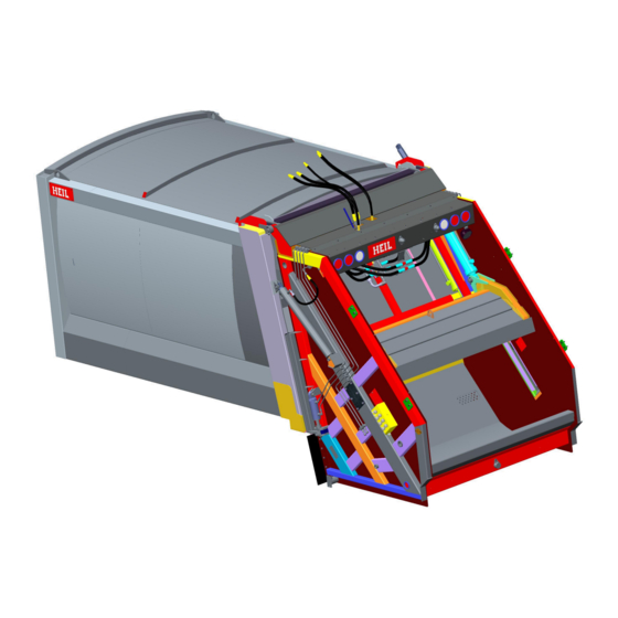
- Page 18 PT 1000A NOMENCLATURE The following illustration shows the major components and their typical locations on the unit. Issued January 2016 Copyright 2016, Heil Environmental Section 1 - General Information...
- Page 19 PT 1000A RECOMMENDED SPARE PARTS The table below shows a list of recommended spare parts for your unit. PART DESCRIPTION NUMBER Body Assembly 022-3509 SEAL, Tailgate 003-4657 PLATE, Wear, Ejector 003-5102 WEAR BAR, Bearing, Inner Slide 021-4085 WEAR BAR, Plastic, Blade Shoe 028-0481 ASSEMBLY, Blade Shoe Controls...
- Page 20 PT 1000A GLOSSARY The Glossary is a collection of terms used in this manual and the explanation for each term. The terms are used in the descriptions of parts. ° Degree ORFS O-Ring Face Seal Number Page Feet Programmable Logic Controller "...
- Page 21 PT 1000A SECTION 2 BODY AND ATTACHING PARTS Copyright 2016, Heil Environmental Issued January 2016 Section 2 - Body and Attaching Parts...
- Page 22 PT 1000A INTENTIONALLY LEFT BLANK Issued January 2016 Copyright 2016, Heil Environmental Section 2 - Body and Attaching Parts...
- Page 23 PT 1000A BODY ASSEMBLIES AND ATTACHING PARTS Copyright 2016, Heil Environmental Issued January 2016 Section 2 - Body and Attaching Parts...
- Page 24 PT 1000A 15/18 YARD BODY ASSEMBLY 612-4052-016 Issued January 2016 Copyright 2016, Heil Environmental Section 2 - Body and Attaching Parts...
- Page 25 PT 1000A 15/18 YARD BODY ASSEMBLY 612-4052-016 ITEM PART NO. DESCRIPTION 612-4052-016 ASSEMBLY, Body, 15/18 Yd..............- ......REF 020-2391-009 PAD, Floor, Oil Tank ................- ......1 020-2655 ASSEMBLY, Oil Tank ..............- ......1 048-5482 PIN, Tailgate Raise, 1” Dia..............- ......2 048-5505 PIN, Rod End, Ejector Cylinder, 5-7/16"...
- Page 26 PT 1000A 15/18 YARD BODY WELDMENT 612-4051-016 Issued January 2016 Copyright 2016, Heil Environmental Section 2 - Body and Attaching Parts...
- Page 27 PT 1000A 15/18 YARD BODY WELDMENT 612-4051-016 ITEM PART NO. DESCRIPTION 612-4051-016 WELDMENT, Body, 15/18 Yd..............- ......REF 021-4456-001 BAR, Seal, Tailgate ................- ......1 021-4456-002 BAR, Seal, Tailgate ................- ......1 113-7041-016 WELDMENT, SS, 15/18 Yd............
- Page 28 PT 1000A 15/18 YARD SS WELDMENT 113-7041-016 Issued January 2016 Copyright 2016, Heil Environmental Section 2 - Body and Attaching Parts...
- Page 29 PT 1000A 15/18 YARD SS WELDMENT 113-7041-016 ITEM PART NO. DESCRIPTION 113-7041-016 WELDMENT, SS, 15/18 Yd..............- ......REF 113-7041-006 PLATE, Closure, Body Side ..............- ......1 MSP23-06-000 NUT, Nyloc, M6 ................... - ......4 Note: Items 1-4 and 6-9 are Welded. Copyright 2016, Heil Environmental Issued January 2016 Section 2 - Body and Attaching Parts...
- Page 30 PT 1000A 15/18 YARD CS WELDMENT 113-7042-016 Issued January 2016 Copyright 2016, Heil Environmental Section 2 - Body and Attaching Parts...
- Page 31 PT 1000A 15/18 YARD SS WELDMENT 113-7041-016 ITEM PART NO. DESCRIPTION 113-7042-016 WELDMENT, CS, 15/18 Yd..............- ......REF Copyright 2016, Heil Environmental Issued January 2016 Section 2 - Body and Attaching Parts...
- Page 32 PT 1000A SUBFRAME WELDMENT 237-9714-016 Issued January 2016 Copyright 2016, Heil Environmental Section 2 - Body and Attaching Parts...
- Page 33 PT 1000A SUBFRAME WELDMENT 237-9714-016 ITEM PART NO. DESCRIPTION 237-9714-016 WELDMENT, Subframe ................. - ......REF 237-9714-006 SHEET, Floor, Front ................- ......1 237-9714-009 SHEET, Floor, Front ................- ......1 237-9714-027 SHEET, Floor, Rear ................- ......1 612-4051-002 PLATE, Floor, 2150 mm ..............
- Page 34 PT 1000A 18/23 YARD BODY ASSEMBLY 612-4052-019 Issued January 2016 Copyright 2016, Heil Environmental Section 2 - Body and Attaching Parts...
- Page 35 PT 1000A 18/23 YARD BODY ASSEMBLY 612-4052-019 ITEM PART NO. DESCRIPTION 612-4052-019 ASSEMBLY, Body, 18/23 Yd..............- ......REF 020-2391-009 PAD, Floor, Oil Tank ................- ......1 020-2655 ASSEMBLY, Oil Tank ..............- ......1 048-5482 PIN, Tailgate Raise, 1” Dia..............- ......2 048-5505 PIN, Rod End, Ejector Cylinder, 5-7/16"...
- Page 36 PT 1000A 18/23 YARD BODY WELDMENT 612-4051-019 Issued January 2016 Copyright 2016, Heil Environmental Section 2 - Body and Attaching Parts...
- Page 37 PT 1000A 18/23 YARD BODY WELDMENT 612-4051-019 ITEM PART NO. DESCRIPTION 612-4051-019 WELDMENT, Body, 18/23 Yd..............- ......REF 021-4456-001 BAR, Seal, Tailgate ................- ......2 021-4456-002 BAR, Seal, Tailgate ................- ......1 237-9714-019 ASSEMBLY, Subframe ..............- ......1 612-4051-003 BRACE, Rear Post ................
- Page 38 PT 1000A 18/23 YARD SS WELDMENT 113-7041-019 Issued January 2016 Copyright 2016, Heil Environmental Section 2 - Body and Attaching Parts...
- Page 39 PT 1000A 18/23 YARD SS WELDMENT 113-7041-019 ITEM PART NO. DESCRIPTION 113-7041-019 WELDMENT, SS, 18/23 Yd..............- ......REF Copyright 2016, Heil Environmental Issued January 2016 Section 2 - Body and Attaching Parts...
- Page 40 PT 1000A 18/23 YARD CS WELDMENT 113-7042-019 Issued January 2016 Copyright 2016, Heil Environmental Section 2 - Body and Attaching Parts...
- Page 41 PT 1000A 18/23 YARD CS WELDMENT 113-7041-019 ITEM PART NO. DESCRIPTION 113-7042-019 WELDMENT, CS, 18/23 Yd..............- ......REF Copyright 2016, Heil Environmental Issued January 2016 Section 2 - Body and Attaching Parts...
- Page 42 PT 1000A SUBFRAME ASSEMBLY 237-9714-019 Issued January 2016 Copyright 2016, Heil Environmental Section 2 - Body and Attaching Parts...
- Page 43 PT 1000A SUBFRAME ASSEMBLY 237-9714-019 ITEM PART NO. DESCRIPTION 237-9714-019 ASSEMBLY, Subframe ................- ......REF 237-9714-006 SHEET, Floor, Front ................- ......1 237-9714-007 SHEET, Floor, Rear ................- ......1 237-9714-009 SHEET, Floor, Front ................- ......1 237-9714-040 SHEET, Floor ..................
- Page 44 PT 1000A 20/25 YARD BODY ASSEMBLY 612-4052-021 Issued January 2016 Copyright 2016, Heil Environmental Section 2 - Body and Attaching Parts...
- Page 45 PT 1000A 20/25 YARD BODY ASSEMBLY 612-4052-021 ITEM PART NO. DESCRIPTION 612-4052-021 ASSEMBLY, Body, 20/25 Yd..............- ......REF 020-2391-009 PAD, Floor, Oil Tank ................- ......1 020-2655 ASSEMBLY, Oil Tank ..............- ......1 048-5482 PIN, Tailgate Raise, 1” Dia..............- ......2 048-5505 PIN, Rod End, Ejector Cylinder, 5-7/16"...
- Page 46 PT 1000A 20/25 YARD BODY WELDMENT 612-4051-021 Issued January 2016 Copyright 2016, Heil Environmental Section 2 - Body and Attaching Parts...
- Page 47 PT 1000A 20/25 YARD BODY WELDMENT 612-4051-021 ITEM PART NO. DESCRIPTION 612-4051-021 WELDMENT, Body, 20/25 Yd..............- ......REF 021-4456-001 BAR, Seal, Tailgate ................- ......2 021-4456-002 BAR, Seal, Tailgate ................- ......1 113-7041-021 WELDMENT, SS, 18/23 Yd............
- Page 48 PT 1000A 20/25 YARD SS WELDMENT 113-7041-021 Issued January 2016 Copyright 2016, Heil Environmental Section 2 - Body and Attaching Parts...
- Page 49 PT 1000A 20/25 YARD SS WELDMENT 113-7041-021 ITEM PART NO. DESCRIPTION 113-7041-021 WELDMENT, SS, 20/25 Yd..............- ......REF 113-7041-006 PLATE, Closure, Body Side ..............- ......1 MSP23-06-000 NUT, Nyloc, M6 ................... - ......4 Note: Items 1-4 and 6-9 are Welded. Copyright 2016, Heil Environmental Issued January 2016 Section 2 - Body and Attaching Parts...
- Page 50 PT 1000A 20/25 YARD CS WELDMENT 113-7042-021 Issued January 2016 Copyright 2016, Heil Environmental Section 2 - Body and Attaching Parts...
- Page 51 PT 1000A 20/25 YARD CS WELDMENT 113-7042-021 ITEM PART NO. DESCRIPTION 113-7042-021 WELDMENT, CS, 20/25 Yd..............- ......REF Copyright 2016, Heil Environmental Issued January 2016 Section 2 - Body and Attaching Parts...
- Page 52 PT 1000A SUBFRAME ASSEMBLY 237-9714-021 Issued January 2016 Copyright 2016, Heil Environmental Section 2 - Body and Attaching Parts...
- Page 53 PT 1000A SUBFRAME ASSEMBLY 237-9714-021 ITEM PART NO. DESCRIPTION 237-9714-021 ASSEMBLY, Subframe ................- ......REF 237-9714-006 SHEET, Floor, Front ................- ......1 237-9714-009 SHEET, Floor, Front ................- ......1 237-9714-036 SHEET, Floor ..................- ......2 612-4051-020 BRACKET, Mount, Air Solenoid ............
- Page 54 PT 1000A 23/30 YARD BODY ASSEMBLY 612-4052-026 Issued January 2016 Copyright 2016, Heil Environmental Section 2 - Body and Attaching Parts...
- Page 55 PT 1000A 23/30 YARD BODY ASSEMBLY 612-4052-026 ITEM PART NO. DESCRIPTION 612-4052-026 ASSEMBLY, Body, 23/30 Yd..............- ......REF 020-2391-009 PAD, Floor, Oil Tank ................- ......1 020-2655 ASSEMBLY, Oil Tank ..............- ......1 048-5482 PIN, Tailgate Raise, 1” Dia..............- ......2 048-5505 PIN, Rod End, Ejector Cylinder, 5-7/16"...
- Page 56 PT 1000A 23/30 YARD BODY WELDMENT 612-4051-026 Issued January 2016 Copyright 2016, Heil Environmental Section 2 - Body and Attaching Parts...
- Page 57 PT 1000A 23/30 YARD BODY WELDMENT 612-4051-026 ITEM PART NO. DESCRIPTION 612-4051-026 WELDMENT, Body, 23/30 Yd..............- ......REF 021-4456-001 BAR, Seal, Tailgate ................- ......2 021-4456-002 BAR, Seal, Tailgate ................- ......1 113-7041-026 WELDMENT, SS, 23/30 Yd............
- Page 58 PT 1000A 23/30 YARD SS WELDMENT 113-7041-026 Issued January 2016 Copyright 2016, Heil Environmental Section 2 - Body and Attaching Parts...
- Page 59 PT 1000A 23/30 YARD SS WELDMENT 113-7041-026 ITEM PART NO. DESCRIPTION 113-7041-026 WELDMENT, SS, 23/30 Yd..............- ......REF 113-7041-006 PLATE, Closure, Body Side ..............- ......1 MSP23-06-000 NUT, Nyloc, M6 ................... - ......4 Note: Items 1-4 and 6-10 are Welded. Copyright 2016, Heil Environmental Issued January 2016 Section 2 - Body and Attaching Parts...
- Page 60 PT 1000A 23/30 YARD CS WELDMENT 113-7042-026 Issued January 2016 Copyright 2016, Heil Environmental Section 2 - Body and Attaching Parts...
- Page 61 PT 1000A 23/30 YARD CS WELDMENT 113-7042-026 ITEM PART NO. DESCRIPTION 113-7042-026 WELDMENT, CS, 23/30 Yd..............- ......REF Copyright 2016, Heil Environmental Issued January 2016 Section 2 - Body and Attaching Parts...
- Page 62 PT 1000A SUBFRAME ASSEMBLY 237-9714-026 Issued January 2016 Copyright 2016, Heil Environmental Section 2 - Body and Attaching Parts...
- Page 63 PT 1000A SUBFRAME ASSEMBLY 237-9714-026 ITEM PART NO. DESCRIPTION 237-9714-026 ASSEMBLY, Subframe ................- ......REF 237-9714-005 SHEET, Floor ..................- ......2 237-9714-006 SHEET, Floor, Front ................- ......1 237-9714-009 SHEET, Floor, Front ................- ......1 237-9714-027 SHEET, Floor, Rear ................
- Page 64 PT 1000A BODY HINGE CROSSMEMBER WELDMENT 237-9715 Issued January 2016 Copyright 2016, Heil Environmental Section 2 - Body and Attaching Parts...
- Page 65 PT 1000A BODY HINGE CROSSMEMBER WELDMENT 237-9715 ITEM PART NO. DESCRIPTION 237-9715 WELDMENT, Body Hinge Crossmember Assy........- ......REF Copyright 2016, Heil Environmental Issued January 2016 Section 2 - Body and Attaching Parts...
- Page 66 PT 1000A INTENTIONALLY LEFT BLANK Issued January 2016 Copyright 2016, Heil Environmental Section 2 - Body and Attaching Parts...
- Page 67 PT 1000A TAILGATE ASSEMBLIES Copyright 2016, Heil Environmental Issued January 2016 Section 2 - Body and Attaching Parts...
- Page 68 PT 1000A TAILGATE ASSEMBLY 615-6654 Issued January 2016 Copyright 2016, Heil Environmental Section 2 - Body and Attaching Parts...
- Page 69 PT 1000A INTENTIONALLY LEFT BLANK Copyright 2016, Heil Environmental Issued January 2016 Section 2 - Body and Attaching Parts...
- Page 70 PT 1000A TAILGATE ASSEMBLY 615-6654 Issued January 2016 Copyright 2016, Heil Environmental Section 2 - Body and Attaching Parts...
- Page 71 PT 1000A INTENTIONALLY LEFT BLANK Copyright 2016, Heil Environmental Issued January 2016 Section 2 - Body and Attaching Parts...
- Page 72 PT 1000A TAILGATE ASSEMBLY 615-6654 Issued January 2016 Copyright 2016, Heil Environmental Section 2 - Body and Attaching Parts...
- Page 73 PT 1000A INTENTIONALLY LEFT BLANK Copyright 2016, Heil Environmental Issued January 2016 Section 2 - Body and Attaching Parts...
- Page 74 PT 1000A TAILGATE ASSEMBLY 615-6654 Issued January 2016 Copyright 2016, Heil Environmental Section 2 - Body and Attaching Parts...
- Page 75 PT 1000A TAILGATE ASSEMBLY 615-6654 ITEM PART NO. DESCRIPTION 615-6654 ASSEMBLY, Tailgate ................- ......REF 001-6863 CYLINDER, Tailgate Raise (See Section 5) ........- ......2 001-6869 CYLINDER, Tailgate Lock (See Section 5) ......... - ......2 022-3509-178 SEAL, Tailgate, .................. - ......1 031-6468-001 VALVE, Regenerative .................
- Page 76 PT 1000A INTENTIONALLY LEFT BLANK Issued January 2016 Copyright 2016, Heil Environmental Section 2 - Body and Attaching Parts...
- Page 77 PT 1000A TAILGATE ASSEMBLY 615-6654 ITEM PART NO. DESCRIPTION 354-4814-012 ELBOW, Male, 45° ................- ......2 354-4814-020 ELBOW, 45° ..................- ......1 354-4815-012 ELBOW, 37° Flare, 90 SAE to 12 mm ..........- ......4 354-4815-020 ELBOW, #12 SAE to 20 mm ............... - ......3 354-4815-021 ELBOW, #10 SAE to 20 mm ...............
- Page 78 PT 1000A BLADE AND SLIDE ASSEMBLY 237-9692 Issued January 2016 Copyright 2016, Heil Environmental Section 2 - Body and Attaching Parts...
- Page 79 PT 1000A BLADE AND SLIDE ASSEMBLY 237-9692 ITEM PART NO. DESCRIPTION 237-9692 ASSEMBLY, Blade & Slide ..............- ......REF 001-7077 CYLINDER, Blade (See Section 5) ............. - ......2 001-7076 CYLINDER, Slide (See Section 5) ............- ......2 003-3906 BEARING, Packing Blade ..............
- Page 80 PT 1000A BLADE SHOE ASSEMBLY 028-0481 Issued January 2016 Copyright 2016, Heil Environmental Section 2 - Body and Attaching Parts...
- Page 81 PT 1000A BLADE SHOE ASSEMBLY 028-0481 ITEM PART NO. DESCRIPTION 028-0481 ASSEMBLY, Blade Shoe ................ - ......REF 003-3902 PAD, Bearing, Shoe Side ..............- ......2 021-4085 BAR, Wear, Plastic, Blade Shoe ............- ......2 234-2098 PLATE, Blade Shoe, 1/2" ..............- ......4 Note: Items 2 and 5 are Welded.
- Page 82 PT 1000A LOWER BLADE PANEL ASSEMBLY 113-6976 Issued January 2016 Copyright 2016, Heil Environmental Section 2 - Body and Attaching Parts...
- Page 83 PT 1000A LOWER BLADE PANEL ASSEMBLY 113-6976 ITEM PART NO. DESCRIPTION 113-6976 ASSEMBLY, Blade Panel, Lower ............- ......REF 113-6976-001 SHEET, Face, Lower Panel, 5 mm ............. - ......1 113-6976-002 CROSS BRACE, Panel, Lower, 3 mm ..........- ......1 113-6976-003 BRACE, Angle, Panel Lower, 3 mm ............
- Page 84 PT 1000A BLADE AND SLIDE OUTER SLIDE ASSEMBLY 237-9693 Issued January 2016 Copyright 2016, Heil Environmental Section 2 - Body and Attaching Parts...
- Page 85 PT 1000A BLADE AND SLIDE OUTER SLIDE ASSEMBLY 237-9693 ITEM PART NO. DESCRIPTION 237-9693 ASSEMBLY, Outer Slide, Blade & Slide ..........- ......REF 047-2684 NUT, Weld, 10 mm ................- ......4 237-9693-004 BRACE, Outer Slide, 6 mm ..............- ......1 237-9693-011 STIFFENER, Outer Slide, 6 mm ............
- Page 86 PT 1000A INNER SLIDE ASSEMBLY 237-9694 Issued January 2016 Copyright 2016, Heil Environmental Section 2 - Body and Attaching Parts...
- Page 87 PT 1000A INNER SLIDE ASSEMBLY 237-9694 ITEM PART NO. DESCRIPTION 237-9694 ASSEMBLY, Inner Slide ................. - ......REF 003-5102 BAR, Bearing, Inner Slide ..............- ......4 047-2533 HHCS, 1/2"-13 x 3/4", Brass ............... - ......4 047-2534 WASHER, Flat, 1/2" SAE, Brass ............- ......4 237-9694-001 CHANNEL, Inner Slide, 6 mm, SS ............
- Page 88 PT 1000A TAILGATE WELDMENT 615-6653 Issued January 2016 Copyright 2016, Heil Environmental Section 2 - Body and Attaching Parts...
- Page 89 PT 1000A TAILGATE WELDMENT 615-6653 ITEM PART NO. DESCRIPTION 615-6653 WELDMENT, Tailgate ................- ......REF 036-1122-012 CLAMP, Wire, Tube, 3/4" x 13/32” ............- ......2 113-6981 WELDMENT, Tailgate, SS ............- ......1 113-6982 WELDMENT, Tailgate, CS ............- ......1 177-2923-008 CHANNEL, Vertical, Tailgate, 42"...
- Page 90 PT 1000A 25 YARD TAILGATE CROSS MEMBER 177-5842 Issued January 2016 Copyright 2016, Heil Environmental Section 2 - Body and Attaching Parts...
- Page 91 PT 1000A 25 YARD TAILGATE CROSS MEMBER 177-5842 ITEM PART NO. DESCRIPTION 177-5842 CROSS MEMBER, Tailgate, 25 Yd............- ......REF 177-5842-001 CROSS MEMBER, 10 mm ..............- ......1 177-5842-002 HINGE, Tailgate, 50 mm ..............- ......2 177-5842-003 HINGE, Slide, 38 mm ................
- Page 92 PT 1000A SS TAILGATE WELDMENT 113-6981 Issued January 2016 Copyright 2016, Heil Environmental Section 2 - Body and Attaching Parts...
- Page 93 PT 1000A SS TAILGATE WELDMENT 113-6981 ITEM PART NO. DESCRIPTION 113-6981 WELDMENT, Tailgate, SS ..............- ......REF 036-1597-M12 CLAMP, Tube, 12 mm ................. - ......11 113-6981-004 BRACE, 3 mm, SS ................- ......1 113-6981-006 BRACE, 4 mm, SS ................- ......1 113-6981-007 BRACE, 3 mm, SS ................
- Page 94 PT 1000A SS SLIDE TRACK WELDMENT 113-6981-100 Issued January 2016 Copyright 2016, Heil Environmental Section 2 - Body and Attaching Parts...
- Page 95 PT 1000A SS SLIDE TRACK WELDMENT 113-6981-100 ITEM PART NO. DESCRIPTION 113-6981-100 WELDMENT, Track, Slide, SS ............... - ......REF 055-1391-003 WASHER, Steel, Hardened, 3/8” x 0.8” Thickness, Zinc Plated ..- ......6 113-6981-101 BRACE, Slide Track, 6 mm ..............- ......1 113-6981-102 BRACE, 6 mm ..................
- Page 96 PT 1000A CS TAILGATE WELDMENT 113-6982 Issued January 2016 Copyright 2016, Heil Environmental Section 2 - Body and Attaching Parts...
- Page 97 PT 1000A CS TAILGATE WELDMENT 113-6982 ITEM PART NO. DESCRIPTION 113-6982 WELDMENT, Tailgate, CS ..............- ......REF 036-1597-M12 CLAMP, Tube, 12 mm ................. - ......11 113-6981-008 BRACE, 3 mm ..................- ......2 113-6981-012 BRACE, 3 mm ..................- ......1 113-6981-013 SLEEVE, Black Pipe, 60 mm ID x 70 mm OD ........
- Page 98 PT 1000A SS SLIDE TRACK WELDMENT 113-6982-100 Issued January 2016 Copyright 2016, Heil Environmental Section 2 - Body and Attaching Parts...
- Page 99 PT 1000A SS SLIDE TRACK WELDMENT 113-6982-100 ITEM PART NO. DESCRIPTION 113-6982-100 WELDMENT, Track, Slide, SS ............... - ......REF 055-1391-003 WASHER, Steel, Hardened, 3/8” x 0.8” Thickness, Zinc Plated ..- ......6 113-6981-102 BRACE, 6 mm ..................- ......1 113-6981-103 BRACE, 6 mm ..................
- Page 100 PT 1000A DRAIN KIT 031-6571 Issued January 2016 Copyright 2016, Heil Environmental Section 2 - Body and Attaching Parts...
- Page 101 PT 1000A DRAIN KIT 031-6571 ITEM PART NO. DESCRIPTION 031-6571 KIT, Drain ....................- ......REF 031-6571-001 TUBE, Drain ..................- ......1 031-6571-002 COVER, Drain ..................- ......1 Copyright 2016, Heil Environmental Issued January 2016 Section 2 - Body and Attaching Parts...
- Page 102 PT 1000A INTENTIONALLY LEFT BLANK Issued January 2016 Copyright 2016, Heil Environmental Section 2 - Body and Attaching Parts...
- Page 103 PT 1000A MOUNTING KITS Copyright 2016, Heil Environmental Issued January 2016 Section 2 - Body and Attaching Parts...
- Page 104 PT 1000A MOUNT KIT 372-7823 Issued January 2016 Copyright 2016, Heil Environmental Section 2 - Body and Attaching Parts...
- Page 105 PT 1000A MOUNT KIT 372-7823 ITEM PART NO. DESCRIPTION 372-7823 KIT, Mount ....................- ......REF 311-6016 BRACKET, Support, Mudflap .............. - ......2 019-1219 SPRING, Compression ............... - ......4 311-6014 BRACKET, Mount, Rear, 1-1/4" ............- ......2 Note: Items 1, 4, 5 and 7 are Welded.
- Page 106 PT 1000A INTENTIONALLY LEFT BLANK Issued January 2016 Copyright 2016, Heil Environmental Section 2 - Body and Attaching Parts...
- Page 107 PT 1000A OIL TANK KIT Copyright 2016, Heil Environmental Issued January 2016 Section 2 - Body and Attaching Parts...
- Page 108 PT 1000A OIL TANK ASSEMBLY 020-2655 Issued January 2016 Copyright 2016, Heil Environmental Section 2 - Body and Attaching Parts...
- Page 109 PT 1000A OIL TANK ASSEMBLY 020-2655 ITEM PART NO. DESCRIPTION 020-2655 ASSEMBLY, Oil Tank ................- ......REF 020-2656 WELDMENT, Oil Tank, Hydraulic ..........- ......1 031-2616 VALVE, Shut Off, Suction Line, 2" ............- ......1 060-0800 CAP, Filler, Breather, Plastic ............... - ......1 067-0630 GAUGE, Sight, Thermometer .............
- Page 110 PT 1000A HYDRAULIC OIL TANK WELDMENT 020-2656 Issued January 2016 Copyright 2016, Heil Environmental Section 2 - Body and Attaching Parts...
- Page 111 PT 1000A HYDRAULIC OIL TANK WELDMENT 020-2656 ITEM PART NO. DESCRIPTION 020-2656 WELDMENT, Oil Tank, Hydraulic ............- ......REF 020-2656-008 PAD, Mount, Oil Tank ................. - ......1 FS883040 NIPPLE, Pipe, Black, Std., 2" x 3" ............- ......1 Note: Items 1-7 and 9 are Welded.
- Page 112 PT 1000A INTENTIONALLY LEFT BLANK Issued January 2016 Copyright 2016, Heil Environmental Section 2 - Body and Attaching Parts...
- Page 113 PT 1000A EJECTOR PANEL Copyright 2016, Heil Environmental Issued January 2016 Section 2 - Body and Attaching Parts...
- Page 114 PT 1000A EJECTOR PANEL ASSEMBLY 237-9712 Issued January 2016 Copyright 2016, Heil Environmental Section 2 - Body and Attaching Parts...
- Page 115 PT 1000A EJECTOR PANEL ASSEMBLY 237-9712 ITEM PART NO. DESCRIPTION 237-9712 ASSEMBLY, Panel, Ejector ..............- ......REF 003-4657 PLATE, Wear ..................- ......4 021-4452 PLATE, Wear ..................- ......4 MSP23-08-000 NUT, Nyloc M8 ..................- ......8 047-2239-002 BOLT, Countersunk, M10x40 ..............
- Page 116 PT 1000A INTENTIONALLY LEFT BLANK Issued January 2016 Copyright 2016, Heil Environmental Section 2 - Body and Attaching Parts...
- Page 117 PT 1000A DECAL KIT Copyright 2016, Heil Environmental Issued January 2016 Section 2 - Body and Attaching Parts...
- Page 118 PT 1000A DECAL KIT 212-1779 Issued January 2016 Copyright 2016, Heil Environmental Section 2 - Body and Attaching Parts...
- Page 119 PT 1000A INTENTIONALLY LEFT BLANK Copyright 2016, Heil Environmental Issued January 2016 Section 2 - Body and Attaching Parts...
- Page 120 PT 1000A DECAL KIT 212-1779 Issued January 2016 Copyright 2016, Heil Environmental Section 2 - Body and Attaching Parts...
- Page 121 PT 1000A DECAL KIT 212-1779 ITEM PART NO. DESCRIPTION 212-1779 KIT, Decal ....................- ......REF 212-1600 DECAL, Flood Light ................- ......1 212-1764 DECAL, Danger, Under Chassis, Stop Engine ........- ......4 212-1780 DECAL, Caution, Side Door ..............- ......1 212-1781 DECAL, Caution, Enter Body, Stop Engine .........
- Page 122 PT 1000A CHINESE DECAL KIT 212-1779-CHN Issued January 2016 Copyright 2016, Heil Environmental Section 2 - Body and Attaching Parts...
- Page 123 PT 1000A INTENTIONALLY LEFT BLANK Copyright 2016, Heil Environmental Issued January 2016 Section 2 - Body and Attaching Parts...
- Page 124 PT 1000A CHINESE DECAL KIT 212-1779-CHN Issued January 2016 Copyright 2016, Heil Environmental Section 2 - Body and Attaching Parts...
- Page 125 PT 1000A CHINESE DECAL KIT 212-1779-CHN ITEM PART NO. DESCRIPTION 212-1779-CHN KIT, Decal, Chinese ................- ......REF 212-1600-SC DECAL, Flood Light ................- ......1 212-1764-SC DECAL, Danger, Under Chassis, Stop Engine ........- ......4 212-1781-SC DECAL, Caution, Enter Body, Stop Engine ......... - ......4 212-1782-SC DECAL, Hydraulic Oil Only ..............
- Page 126 PT 1000A INTENTIONALLY LEFT BLANK Issued January 2016 Copyright 2016, Heil Environmental...
- Page 127 PT 1000A SECTION 3 CONTROLS Copyright 2016, Heil Environmental Issued January 2016 Section 3 - Controls...
- Page 128 PT 1000A INTENTIONALLY LEFT BLANK Issued January 2016 Copyright 2016, Heil Environmental Section 3 - Controls...
- Page 129 PT 1000A TAILGATE CONTROL KIT Copyright 2016, Heil Environmental Issued January 2016 Section 3 - Controls...
- Page 130 PT 1000A ELECTRICAL CONTROL KIT 254-4863 NO ILLUSTRATION Issued January 2016 Copyright 2016, Heil Environmental Section 3 - Controls...
- Page 131 PT 1000A ELECTRICAL CONTROL KIT 254-4863 ITEM PART NO. DESCRIPTION 254-4863 KIT, Control, Electrical ................- ......REF 151-4752- L/R PANEL, Control, Rear ................. - ......2 108-8464-001 SWITCH, Work Light, SPST Togle ............. - ......2 031-6566-003 VALVE, Control, Pneumatic, Tailgate (See Section 5) ....... - ......1 108-8464 SWITCH, Toggle, SPST ..............
- Page 132 PT 1000A RELAY PANEL ASSEMBLY 254-4858 Issued January 2016 Copyright 2016, Heil Environmental Section 3 - Controls...
- Page 133 PT 1000A RELAY PANEL ASSEMBLY 254-4858 ITEM PART NO. DESCRIPTION 254-4858 ASSEMBLY, Panel, Relay ..............- ......REF 108-2648 DIODE, Silicon Rectifier ..............- ......5 108-4815-018 SOCKET, Receptacle, 18 Shell ............- ......1 108-4815-180 NUT, Panel, Connector, 18 Shell ............- ......1 108-5666 STRIP, Terminal, Magnum TB300 or Equal ........
- Page 134 PT 1000A 24 VOLTS WEATHER PROOF RELAY ASSEMBLY 108-6752-024 Issued January 2016 Copyright 2016, Heil Environmental Section 3 - Controls...
- Page 135 PT 1000A 24 VOLTS WEATHER PROOF RELAY ASSEMBLY 108-6752-024 ITEM PART NO. DESCRIPTION 108-6752-024 ASSEMBLY, Relay, Weather Proof, 24 V ..........- ......REF 108-6752-005 RELAY, 24 V ..................- ......1 108-6752-002 CONNECTOR ..................- ......1 108-6752-003 TERMINAL ..................- ......4 108-6752-004 PLUG, Packard ...................
- Page 136 PT 1000A MECHANICAL CONTROL KIT 254-4864 NO ILLUSTRATION Issued January 2016 Copyright 2016, Heil Environmental Section 3 - Controls...
- Page 137 PT 1000A MECHANICAL CONTROL KIT 254-4864 ITEM PART NO. DESCRIPTION 254-4864 KIT, Control, Mechanical ................ - ......REF 031-6573 VALVE, Control, Mechanical, Tailgate (See Section 5) ...... - ......1 372-7697 INSTALLATION, Bumper Fill, SS, CNG ..........- ......1 108-8464-001 SWITCH, Work Light, SPST Togle .............
- Page 138 PT 1000A INTENTIONALLY LEFT BLANK Issued January 2016 Copyright 2016, Heil Environmental...
- Page 139 PT 1000A SECTION 4 HYDRAULIC AND PNEUMATIC CIRCUITS Copyright 2016, Heil Environmental Issued January 2016 Section 4 - Hydraulic and Pneumatic Circuits...
- Page 140 PT 1000A INTENTIONALLY LEFT BLANK Issued January 2016 Copyright 2016, Heil Environmental Section 4 - Hydraulic and Pneumatic Circuits...
- Page 141 PT 1000A BODY HYDRAULIC KITS Copyright 2016, Heil Environmental Issued January 2016 Section 4 - Hydraulic and Pneumatic Circuits...
- Page 142 PT 1000A ELECTRICAL & HYDRAULIC BODY CONTROL KIT 372-7824 NO ILLUSTRATION Issued January 2016 Copyright 2016, Heil Environmental Section 4 - Hydraulic and Pneumatic Circuits...
- Page 143 PT 1000A ELECTRICAL & HYDRAULIC BODY CONTROL KIT 372-7824 ITEM PART NO. DESCRIPTION 372-7824 KIT, Control, Body, Electrical & Hydraulic ..........- ......REF 031-6565 VALVE, Body, 3-Section, Pneumatic Actuators (See Section 5) ..- ......1 031-6572 ASSEMBLY, Solenoid Valve (See Section 5) ........- ......1 212-1343 NAME PLATE, Heil ................
- Page 144 PT 1000A IN CAB CONTROL BOX KIT 254-4859 Issued January 2016 Copyright 2016, Heil Environmental Section 4 - Hydraulic and Pneumatic Circuits...
- Page 145 PT 1000A IN CAB CONTROL BOX KIT 254-4859 ITEM PART NO. DESCRIPTION 254-4859 KIT, Control Box, In Cab ................. - ......REF 025-0473-005 PLUG, Hole, 5/8” ................. - ......3 108-2559-010 FUSE, 15 Amp., 1-1/4" Lg..............- ......1 108-7544 SWITCH, Rocker, On-Off ..............
- Page 146 PT 1000A INTENTIONALLY LEFT BLANK Issued January 2016 Copyright 2016, Heil Environmental...
- Page 147 PT 1000A SECTION 5 HYDRAULIC AND PNEUMATIC COMPONENTS Copyright 2016, Heil Environmental Issued January 2016 Section 5 - Hydraulic and Pneumatic Components...
- Page 148 PT 1000A INTENTIONALLY LEFT BLANK Issued January 2016 Copyright 2016, Heil Environmental Section 5 - Hydraulic and Pneumatic Components...
- Page 149 PT 1000A PUMP ASSEMBLIES Copyright 2016, Heil Environmental Issued January 2016 Section 5 - Hydraulic and Pneumatic Components...
- Page 150 PT 1000A HYDRAULIC GEAR PUMP 219-2393 Issued January 2016 Copyright 2016, Heil Environmental Section 5 - Hydraulic and Pneumatic Components...
- Page 151 PT 1000A HYDRAULIC GEAR PUMP 219-2393 ITEM PART NO. DESCRIPTION 219-2393 PUMP, Gear, Hydraulic ................- ......REF 219-2393-101 KIT, Seal, Gear, Hydraulic ..............- ....... - 219-2393-102 KIT, Rebuild, Gear, Hydraulic ..............- ....... - Note: Seal kits and rebuild kits are sold separately. Copyright 2016, Heil Environmental Issued January 2016 Section 5 - Hydraulic and Pneumatic Components...
- Page 152 PT 1000A INTENTIONALLY LEFT BLANK Issued January 2016 Copyright 2016, Heil Environmental Section 5 - Hydraulic and Pneumatic Components...
- Page 153 PT 1000A CYLINDERS Copyright 2016, Heil Environmental Issued January 2016 Section 5 - Hydraulic and Pneumatic Components...
- Page 154 PT 1000A INTENTIONALLY LEFT BLANK Issued January 2016 Copyright 2016, Heil Environmental Section 5 - Hydraulic and Pneumatic Components...
- Page 155 PT 1000A BODY EJECTOR CYLINDERS Copyright 2016, Heil Environmental Issued January 2016 Section 5 - Hydraulic and Pneumatic Components...
- Page 156 PT 1000A 16 YARD BODY EJECTOR CYLINDER 001-7098 Issued January 2016 Copyright 2016, Heil Environmental Section 5 - Hydraulic and Pneumatic Components...
- Page 157 PT 1000A 16 YARD BODY EJECTOR CYLINDER 001-7098 ITEM PART NO. DESCRIPTION 001-7098 CYLINDER, Ejector, Body, 16 Yard ............- ......REF Copyright 2016, Heil Environmental Issued January 2016 Section 5 - Hydraulic and Pneumatic Components...
- Page 158 PT 1000A 19 YARD BODY EJECTOR CYLINDER 001-7099 Issued January 2016 Copyright 2016, Heil Environmental Section 5 - Hydraulic and Pneumatic Components...
- Page 159 PT 1000A 19 YARD BODY EJECTOR CYLINDER 001-7099 ITEM PART NO. DESCRIPTION 001-7099 CYLINDER, Ejector, Body, 19 Yard ............- ......REF Copyright 2016, Heil Environmental Issued January 2016 Section 5 - Hydraulic and Pneumatic Components...
- Page 160 PT 1000A 5 STAGE DOUBLE ACTING TELESCOPIC CYLINDER 001-7100 Issued January 2016 Copyright 2016, Heil Environmental Section 5 - Hydraulic and Pneumatic Components...
- Page 161 PT 1000A 5 STAGE DOUBLE ACTING TELESCOPIC CYLINDER 001-7100 ITEM PART NO. DESCRIPTION 001-7100 CYLINDER, Telescopic, DA, 5 Stage ............. - ......REF Copyright 2016, Heil Environmental Issued January 2016 Section 5 - Hydraulic and Pneumatic Components...
- Page 162 PT 1000A 5 STAGE EJECTOR CYLINDER 001-7102 Issued January 2016 Copyright 2016, Heil Environmental Section 5 - Hydraulic and Pneumatic Components...
- Page 163 PT 1000A 5 STAGE EJECTOR CYLINDER 001-7102 ITEM PART NO. DESCRIPTION 001-7102 CYLINDER, Ejector, 5 Stage ..............- ......REF Copyright 2016, Heil Environmental Issued January 2016 Section 5 - Hydraulic and Pneumatic Components...
- Page 164 PT 1000A BLADE CYLINDER 001-7077 Issued January 2016 Copyright 2016, Heil Environmental Section 5 - Hydraulic and Pneumatic Components...
- Page 165 PT 1000A BLADE CYLINDER 001-7077 ITEM PART NO. DESCRIPTION 001-7077 CYLINDER, Blade .................. - ......REF 001-7077-101 KIT, Seal, Blade Cylinder ..............- ......REF Note: Seal kits are sold separately. Copyright 2016, Heil Environmental Issued January 2016 Section 5 - Hydraulic and Pneumatic Components...
- Page 166 PT 1000A SLIDE CYLINDER 001-7076 Issued January 2016 Copyright 2016, Heil Environmental Section 5 - Hydraulic and Pneumatic Components...
- Page 167 PT 1000A SLIDE CYLINDER 001-7076 ITEM PART NO. DESCRIPTION 001-7076 CYLINDER, Slide ..................- ......REF 001-7076-101 KIT, Seal, Slide Cylinder ..............- ......REF Note: Seal kits are sold separately. Copyright 2016, Heil Environmental Issued January 2016 Section 5 - Hydraulic and Pneumatic Components...
- Page 168 PT 1000A TAILGATE RAISE CYLINDER 001-6863 Issued January 2016 Copyright 2016, Heil Environmental Section 5 - Hydraulic and Pneumatic Components...
- Page 169 PT 1000A TAILGATE RAISE CYLINDER 001-6863 ITEM PART NO. DESCRIPTION 001-6863 CYLINDER, Raise, Tailgate ..............- ......REF 001-6863-9180 SEAL KIT ....................- ......REF Note: Seal kits are sold separately. Copyright 2016, Heil Environmental Issued January 2016 Section 5 - Hydraulic and Pneumatic Components...
- Page 170 PT 1000A TAILGATE LOCK CYLINDER 001-6869 Issued January 2016 Copyright 2016, Heil Environmental Section 5 - Hydraulic and Pneumatic Components...
- Page 171 PT 1000A TAILGATE LOCK CYLINDER 001-6869 ITEM PART NO. DESCRIPTION 001-6869 CYLINDER, Tailgate Lock ..............- ......REF 001-6869-101 SEAL KIT ....................- ......REF Note: Seal kits are sold separately. Copyright 2016, Heil Environmental Issued January 2016 Section 5 - Hydraulic and Pneumatic Components...
- Page 172 PT 1000A INTENTIONALLY LEFT BLANK Issued January 2016 Copyright 2016, Heil Environmental Section 5 - Hydraulic and Pneumatic Components...
- Page 173 PT 1000A VALVES Copyright 2016, Heil Environmental Issued January 2016 Section 5 - Hydraulic and Pneumatic Components...
- Page 174 PT 1000A EJECTOR AND TAILGATE CONTROL VALVE 031-6558 Issued January 2016 Copyright 2016, Heil Environmental Section 5 - Hydraulic and Pneumatic Components...
- Page 175 PT 1000A EJECTOR AND TAILGATE CONTROL VALVE 031-6558 ITEM PART NO. DESCRIPTION 031-6558 VALVE, Control, Tailgate ................ - ......REF 031-6558-189 SECTION, Inlet ..................- ......1 031-6558-182 SECTION, ejector ................... - ......1 031-6558-183 SECTION, Tailgate ................. - ......1 031-6558-184 SECTION, Tailgate .................
- Page 176 PT 1000A INLET SECTION 031-6558-189 Issued January 2016 Copyright 2016, Heil Environmental Section 5 - Hydraulic and Pneumatic Components...
- Page 177 PT 1000A INLET SECTION 031-6558-189 ITEM PART NO. DESCRIPTION 031-6558-189 INLET SECTION-(consists of items 1 thru 18) ........- ......REF 031-3285-007 HOUSING ....................- ......1 031-6558-101 SEAL O-RING -0.924 I.D................ - ......1 031-6558-102 3/4" O.D. TUBE(SAE 12) ................ - ......2 031-6558-103 RELIEF, 'WHA'(consists of items 5 thru 18) ...........
- Page 178 PT 1000A EJECTOR WORKING VALVE SECTION 031-6558-0182 Issued January 2016 Copyright 2016, Heil Environmental Section 5 - Hydraulic and Pneumatic Components...
- Page 179 PT 1000A EJECTOR WORKING VALVE SECTION 031-6558-0182 ITEM PART NO. DESCRIPTION 031-6558-0182 VALVE SECTION-(consists of items 1 thru 29) ........- ......REF 031-6558-117 UMBRELLA CHECK VALVE ..............- ......1 031-6558-118 SCREW HSHC1/4-20X.875 ..............- ......6 031-6558-119 BONNET ....................- ......1 031-6558-120 COLLAR, V20, SPRING .................
- Page 180 PT 1000A TAILGATE WORKING VALVE SECTION 031-6558-0183 Issued January 2016 Copyright 2016, Heil Environmental Section 5 - Hydraulic and Pneumatic Components...
- Page 181 PT 1000A TAILGATE WORKING VALVE SECTION 031-6558-0183 ITEM PART NO. DESCRIPTION 031-6558-0183 VALVE SECTION-(consists of items 1 thru 29) ........- ......REF 031-6558-117 UMBRELLA CHECK VALVE ..............- ......1 031-6558-118 SCREW HSHC1/4-20X.875 ..............- ......6 031-6558-119 BONNET ....................- ......1 031-6558-120 COLLAR, V20, SPRING .................
- Page 182 PT 1000A TAILGATE WORKING VALVE SECTION 031-6558-0184 Issued January 2016 Copyright 2016, Heil Environmental Section 5 - Hydraulic and Pneumatic Components...
- Page 183 PT 1000A TAILGATE WORKING VALVE SECTION 031-6558-0184 ITEM PART NO. DESCRIPTION 031-6558-0184 VALVE SECTION-(consists of items 1 thru 29) ........- ......REF 031-6558-117 UMBRELLA CHECK VALVE ..............- ......1 031-6558-118 SCREW HSHC1/4-20X.875 ..............- ......6 031-6558-119 BONNET ....................- ......1 031-6558-120 COLLAR, V20, SPRING .................
- Page 184 PT 1000A UNDER BODY CONTROL VALVE OUTLET SECTION 031-3285-003 Issued January 2016 Copyright 2016, Heil Environmental Section 5 - Hydraulic and Pneumatic Components...
- Page 185 PT 1000A UNDER BODY CONTROL VALVE OUTLET SECTION 031-3285-003 ITEM PART NO. DESCRIPTION 031-3285-003 OUTLET SECTION-(consists of items 1 thru 7) ........- ......REF 031-3285-101 COVER CP ..................... - ......1 031-3285-060 SEAL, O-RING-AS017, 90 ..............- ......1 031-3285-102 RING, BACKUP ..................
- Page 186 PT 1000A TAILGATE MECHANICAL CONTROL VALVE 031-6573 Issued January 2016 Copyright 2016, Heil Environmental Section 5 - Hydraulic and Pneumatic Components...
- Page 187 PT 1000A TAILGATE MECHANICAL CONTROL VALVE 031-6573 ITEM PART NO. DESCRIPTION 031-6573 VALVE, Control, Mechanical, Tailgate ........... - ......REF 031-6573-188 INLET SECTION ................... - ......1 031-6573-185 AUX. SECTION ..................- ......1 031-6573-186 SECTION panel ..................- ......1 031-6573-187 SECTION panel ..................
- Page 188 PT 1000A INLET SECTION 031-6573-188 Issued January 2016 Copyright 2016, Heil Environmental Section 5 - Hydraulic and Pneumatic Components...
- Page 189 PT 1000A INLET SECTION 031-6573-188 ITEM PART NO. DESCRIPTION 031-6573-188 VALVE SECTION-(consists of items 1 thru 7) ........- ......REF 031-3285-007 HOUSING ....................- ......1 031-6558-116 SEAL, O-RING-AS022, 90 ..............- ......1 031-3285-057 RING, BACKUP-AS022 ................- ......1 031-6558-115 SEAL, O-RING-AS023, 90 ..............
- Page 190 PT 1000A AUXILIARY WORKING VALVE SECTION 031-6573-185 Issued January 2016 Copyright 2016, Heil Environmental Section 5 - Hydraulic and Pneumatic Components...
- Page 191 PT 1000A AUXILIARY WORKING VALVE SECTION 031-6573-185 ITEM PART NO. DESCRIPTION 031-6573-185 VALVE SECTION, Auxiliary-(consists of items 1 thru 33) ...... - ......REF 031-6573-105 HOUSING ....................- ......1 031-6558-120 COLLAR, V20, SPRING ................. - ......2 207-5535 COLLAR, V20, SP00L................- ......1 031-6558-121 SPRING-1.135 O.D.
-
Page 192: Panel Working Valve Section
PT 1000A PANEL WORKING VALVE SECTION 031-6573-186 Issued January 2016 Copyright 2016, Heil Environmental Section 5 - Hydraulic and Pneumatic Components... - Page 193 PT 1000A PANEL WORKING VALVE SECTION 031-6573-186 ITEM PART NO. DESCRIPTION 031-6573-186 VALVE SECTION-(consists of items 1 thru 48) ........- ......REF 031-6573-116 HOUSING ....................- ......1 031-3285-014 PLUG, LOAD CHECK(consists of items 3 thru 10) ........ - ......1 031-6558-139 PLUG ......................
- Page 194 PT 1000A PANEL WORKING VALVE SECTION 031-6573-187 Issued January 2016 Copyright 2016, Heil Environmental Section 5 - Hydraulic and Pneumatic Components...
- Page 195 PT 1000A PANEL WORKING VALVE SECTION 031-6573-187 ITEM PART NO. DESCRIPTION 031-6573-187 VALVE SECTION-(consists of items 1 thru 48) ........- ......REF 031-6573-141 HOUSING ....................- ......1 031-3285-014 PLUG, LOAD CHECK(consists of items 3 thru 10) ........ - ......1 031-6558-139 PLUG ......................
-
Page 196: Outlet Section
PT 1000A OUTLET SECTION 031-6573-178 Issued January 2016 Copyright 2016, Heil Environmental Section 5 - Hydraulic and Pneumatic Components... - Page 197 PT 1000A OUTLET SECTION 031-6573-178 ITEM PART NO. DESCRIPTION 031-6573-178 OUTLET SECTION-(consists of items 1 thru 4) ........- ......REF 031-6573-102 COVER CP ..................... - ......1 031-6573-103 PLUG ...................... - ......1 031-3285-104 SEAL, O-RING-AS117, 90 ..............- ......2 031-5698-006 SEAL, O-RING-AS119, 75 ..............
- Page 198 PT 1000A TAILGATE PNEUMATIC CONTROL VALVE 031-6566-003 Issued January 2016 Copyright 2016, Heil Environmental Section 5 - Hydraulic and Pneumatic Components...
- Page 199 PT 1000A TAILGATE PNEUMATIC CONTROL VALVE 031-6566-003 ITEM PART NO. DESCRIPTION 031-6566-003 VALVE, Control, Pneumatic, Tailgate ............. - ......REF 031-6566-167 SECTION, Inlet ..................- ......1 031-6566-174 SECTION, ejector ................... - ......1 031-6566-175 SECTION, Tailgate ................. - ......1 031-6566-176 SECTION, Tailgate .................
- Page 200 PT 1000A INLET SECTION 031-6566-167 Issued January 2016 Copyright 2016, Heil Environmental Section 5 - Hydraulic and Pneumatic Components...
- Page 201 PT 1000A INLET SECTION 031-6566-167 ITEM PART NO. DESCRIPTION 031-6566-167 VALVE SECTION-(consists of items 1 thru 7) ........- ......REF 031-3285-007 HOUSING ....................- ......1 031-6558-116 SEAL, O-RING-AS022, 90 ..............- ......1 031-3285-057 RING, BACKUP-AS022 ................- ......1 031-6558-115 SEAL, O-RING-AS023, 90 ..............
- Page 202 PT 1000A AUXILIARY WORKING VALVE SECTION 031-6566-174 Issued January 2016 Copyright 2016, Heil Environmental Section 5 - Hydraulic and Pneumatic Components...
- Page 203 PT 1000A AUXILIARY WORKING VALVE SECTION 031-6566-174 ITEM PART NO. DESCRIPTION 031-6566-174 VALVE SECTION-(consists of items 1 thru 46) ........- ......REF 031-6573-105 HOUSING ....................- ......1 031-3285-012 SPOOL, 4-WAY, 0.75 DIA..............- ......1 031-6566-101 SEAL, O-RING-AS210, 75 ..............- ......2 031-6558-123 WASHER V20 SPOOL SEAL BACK-UP ..........
- Page 204 PT 1000A PANEL WORKING VALVE SECTION 031-6566-175 Issued January 2016 Copyright 2016, Heil Environmental Section 5 - Hydraulic and Pneumatic Components...
- Page 205 PT 1000A PANEL WORKING VALVE SECTION 031-6566-175 ITEM PART NO. DESCRIPTION 031-6566-175 VALVE SECTION-(consists of items 1 thru 47) ........- ......REF 031-6573-105 HOUSING ....................- ......1 031-3285-012 SPOOL, 4-WAY, 0.75 DIAMETER............- ......1 031-6558-124 SEAL, O-RING-AS210, 75 ..............- ......2 031-6558-123 WASHER V20 SPOOL SEAL BACK-UP ..........
- Page 206 PT 1000A PANEL WORKING VALVE SECTION 031-6566-176 Issued January 2016 Copyright 2016, Heil Environmental Section 5 - Hydraulic and Pneumatic Components...
- Page 207 PT 1000A PANEL WORKING VALVE SECTION 031-6566-176 ITEM PART NO. DESCRIPTION 031-6566-176 VALVE SECTION-(consists of items 1 thru 38) ........- ......REF 031-6573-105 HOUSING ....................- ......1 031-3285-012 SPOOL, 4-WAY, 0.75 DIA..............- ......1 031-6558-124 SEAL, O-RING-AS210, 75 ..............- ......2 031-6558-123 WASHER V20 SPOOL SEAL BACK-UP ..........
- Page 208 PT 1000A OUTLET SECTION 031-6573-178 Issued January 2016 Copyright 2016, Heil Environmental Section 5 - Hydraulic and Pneumatic Components...
- Page 209 PT 1000A OUTLET SECTION 031-6573-178 ITEM PART NO. DESCRIPTION 031-6573-178 OUTLET SECTION-(consists of items 1 thru 4) ........- ......REF 031-6573-102 COVER CP ..................... - ......1 031-6573-103 PLUG ...................... - ......1 031-3285-104 SEAL, O-RING-AS117, 90 ..............- ......2 031-5698-006 SEAL, O-RING-AS119, 75 ..............
-
Page 210: 3-Section Pneumatic Actuators Body Valve
PT 1000A 3-SECTION PNEUMATIC ACTUATORS BODY VALVE 031-6565 Issued January 2016 Copyright 2016, Heil Environmental Section 5 - Hydraulic and Pneumatic Components... - Page 211 PT 1000A 3-SECTION PNEUMATIC ACTUATORS BODY VALVE 031-6565 ITEM PART NO. DESCRIPTION 031-6565 VALVE, Body, 3-Section, Pneumatic Actuators ........- ......REF 031-6565-177 SECTION, Inlet ..................- ......1 031-6565-171 SECTION, ejector ................... - ......1 031-6565-173 SECTION, Tailgate ................. - ......1 031-6565-172 SECTION, Tailgate .................
-
Page 212: Inlet Section
PT 1000A INLET SECTION 031-6565-177 Issued January 2016 Copyright 2016, Heil Environmental Section 5 - Hydraulic and Pneumatic Components... - Page 213 PT 1000A INLET SECTION 031-6565-177 ITEM PART NO. DESCRIPTION 031-6565-177 INLET SECTION-(consists of items 1 thru 20) ........- ......REF 031-3285-007 HOUSING ....................- ......1 031-6558-101 SEAL O-RING -0.924 I.D................ - ......2 031-6558-102 3/4" O.D. TUBE(SAE 12) ................ - ......1 031-6565-101 PLUG, SAE#12 W/GAGE PORT ............
- Page 214 PT 1000A EJECTOR WORKING VALVE SECTION 031-6565-171 Issued January 2016 Copyright 2016, Heil Environmental Section 5 - Hydraulic and Pneumatic Components...
- Page 215 PT 1000A EJECTOR WORKING VALVE SECTION 031-6565-171 ITEM PART NO. DESCRIPTION 031-6565-171 VALVE SECTION-(consists of items 1 thru 37) ........- ......REF 031-6495-301 HOUSING ....................- ......1 031-6558-140 CARTRIDGE RELIEF ASSEMBLY ............- ......1 031-3285-012 SPOOL, 4-WAY, 0.75 DIAMETER ............- ......1 031-6558-124 SEAL, O-RING-AS210, 75 ..............
- Page 216 PT 1000A TAILGATE WORKING VALVE SECTION 031-6565-173 Issued January 2016 Copyright 2016, Heil Environmental Section 5 - Hydraulic and Pneumatic Components...
- Page 217 PT 1000A TAILGATE WORKING VALVE SECTION 031-6565-173 ITEM PART NO. DESCRIPTION 031-6565-173 VALVE SECTION-(consists of items 1 thru 37) ........- ......REF 031-3285-011 HOUSING ....................- ......1 031-3285-012 SPOOL, 4-WAY, 0.75 DIAMETER ............- ......1 031-6558-124 SEAL, O-RING-AS210, 75 ..............- ......2 031-6558-123 WASHER V20 SPOOL SEAL BACK-UP ..........
- Page 218 PT 1000A TAILGATE WORKING VALVE SECTION 031-6565-172 Issued January 2016 Copyright 2016, Heil Environmental Section 5 - Hydraulic and Pneumatic Components...
- Page 219 PT 1000A TAILGATE WORKING VALVE SECTION 031-6565-172 ITEM PART NO. DESCRIPTION 031-6565-172 VALVE SECTION-(consists of items 1 thru 40) ........- ......REF 031-3285-011 HOUSING ....................- ......1 031-6565-103 SPOOL, 4-WAY, 0.75 DIA ..............- ......1 031-6558-124 SEAL, O-RING-AS210, 75 ..............- ......2 031-6558-123 WASHER V20 SPOOL SEAL BACK-UP ..........
- Page 220 PT 1000A UNDER BODY CONTROL VALVE OUTLET SECTION 031-3285-003 Issued January 2016 Copyright 2016, Heil Environmental Section 5 - Hydraulic and Pneumatic Components...
- Page 221 PT 1000A UNDER BODY CONTROL VALVE OUTLET SECTION 031-3285-003 ITEM PART NO. DESCRIPTION 031-3285-003 OUTLET SECTION-(consists of items 1 thru 7) ........- ......REF 031-3285-101 COVER CP ..................... - ......1 031-3285-060 SEAL, O-RING-AS017, 90 ..............- ......1 031-3285-102 RING, BACKUP ..................
-
Page 222: Optional 4-Section Tailgate Valve
PT 1000A OPTIONAL 4-SECTION TAILGATE VALVE 031-6566-004 Issued January 2016 Copyright 2016, Heil Environmental Section 5 - Hydraulic and Pneumatic Components... - Page 223 PT 1000A OPTIONAL 4-SECTION TAILGATE VALVE 031-6566-004 ITEM PART NO. DESCRIPTION 031-6566-004 VALVE, Optional 4-Section Tailgate ............- ......REF 031-6566-167 SECTION, Inlet ..................- ......1 031-6566-213 SECTION, Auxiliary ................- ......1 031-6566-174 SECTION, Auxiliary ................- ......1 031-6566-175 SECTION, Panel ..................
-
Page 224: Inlet Section
PT 1000A INLET SECTION 031-6566-167 Issued January 2016 Copyright 2016, Heil Environmental Section 5 - Hydraulic and Pneumatic Components... - Page 225 PT 1000A INLET SECTION 031-6566-167 ITEM PART NO. DESCRIPTION 031-6566-167 VALVE SECTION-(consists of items 1 thru 7) ........- ......REF 031-3285-007 HOUSING ....................- ......1 031-6558-116 SEAL, O-RING-AS022, 90 ..............- ......1 031-3285-057 RING, BACKUP-AS022 ................- ......1 031-6558-115 SEAL, O-RING-AS023, 90 ..............
-
Page 226: Auxiliary Working Valve Section
PT 1000A AUXILIARY WORKING VALVE SECTION 031-6566-213 Issued January 2016 Copyright 2016, Heil Environmental Section 5 - Hydraulic and Pneumatic Components... - Page 227 PT 1000A AUXILIARY WORKING VALVE SECTION 031-6566-213 ITEM PART NO. DESCRIPTION 031-6565-213 VALVE SECTION-(consists of items 1 thru 37) ........- ......REF 031-6573-116 HOUSING ..........................1 031-3285-012 SPOOL, 4-WAY, 0.75 DIA ..............- ......1 031-6558-124 SEAL, O-RING-AS210, 75 ..............- ......2 031-6558-123 WASHER V20 SPOOL SEAL BACK-UP ..........
- Page 228 PT 1000A AUXILIARY WORKING VALVE SECTION 031-6566-174 Issued January 2016 Copyright 2016, Heil Environmental Section 5 - Hydraulic and Pneumatic Components...
- Page 229 PT 1000A AUXILIARY WORKING VALVE SECTION 031-6566-174 ITEM PART NO. DESCRIPTION 031-6566-174 VALVE SECTION-(consists of items 1 thru 46) ........- ......REF 031-6573-105 HOUSING ....................- ......1 031-3285-012 SPOOL, 4-WAY, 0.75 DIA..............- ......1 031-6566-101 SEAL, O-RING-AS210, 75 ..............- ......2 031-6558-123 WASHER V20 SPOOL SEAL BACK-UP ..........
-
Page 230: Panel Working Valve Section
PT 1000A PANEL WORKING VALVE SECTION 031-6566-175 Issued January 2016 Copyright 2016, Heil Environmental Section 5 - Hydraulic and Pneumatic Components... - Page 231 PT 1000A PANEL WORKING VALVE SECTION 031-6566-175 ITEM PART NO. DESCRIPTION 031-6566-175 VALVE SECTION-(consists of items 1 thru 47) ........- ......REF 031-6573-105 HOUSING ....................- ......1 031-3285-012 SPOOL, 4-WAY, 0.75 DIAMETER............- ......1 031-6558-124 SEAL, O-RING-AS210, 75 ..............- ......2 031-6558-123 WASHER V20 SPOOL SEAL BACK-UP ..........
- Page 232 PT 1000A PANEL WORKING VALVE SECTION 031-6566-176 Issued January 2016 Copyright 2016, Heil Environmental Section 5 - Hydraulic and Pneumatic Components...
- Page 233 PT 1000A PANEL WORKING VALVE SECTION 031-6566-176 ITEM PART NO. DESCRIPTION 031-6566-176 VALVE SECTION-(consists of items 1 thru 38) ........- ......REF 031-6573-105 HOUSING ....................- ......1 031-3285-012 SPOOL, 4-WAY, 0.75 DIA..............- ......1 031-6558-124 SEAL, O-RING-AS210, 75 ..............- ......2 031-6558-123 WASHER V20 SPOOL SEAL BACK-UP ..........
-
Page 234: Outlet Section
PT 1000A OUTLET SECTION 031-6573-178 Issued January 2016 Copyright 2016, Heil Environmental Section 5 - Hydraulic and Pneumatic Components... - Page 235 PT 1000A OUTLET SECTION 031-6573-178 ITEM PART NO. DESCRIPTION 031-6573-178 OUTLET SECTION-(consists of items 1 thru 4) ........- ......REF 031-6573-102 COVER CP ..................... - ......1 031-6573-103 PLUG ...................... - ......1 031-3285-104 SEAL, O-RING-AS117, 90 ..............- ......2 031-5698-006 SEAL, O-RING-AS119, 75 ..............
-
Page 236: Auxiliary Control Valve
PT 1000A AUXILIARY CONTROL VALVE 031-6588 Issued January 2016 Copyright 2016, Heil Environmental Section 5 - Hydraulic and Pneumatic Components... - Page 237 PT 1000A AUXILIARY CONTROL VALVE 031-6588 ITEM PART NO. DESCRIPTION 031-6588 VALVE, Control, Auxiliary ............... - ......REF 031-6588-188 SECTION, Inlet ..................- ......1 031-6588-185 SECTION, Auxiliary ................- ......1 031-6588-186 SECTION, Panel ..................- ......1 031-6588-187 SECTION, Panel ..................
-
Page 238: Inlet Section
PT 1000A INLET SECTION 031-6588-188 Issued January 2016 Copyright 2016, Heil Environmental Section 5 - Hydraulic and Pneumatic Components... - Page 239 PT 1000A INLET SECTION 031-6588-188 ITEM PART NO. DESCRIPTION 031-6588-188 VALVE SECTION-(consists of items 1 thru 7) ........- ......REF 031-3285-007 HOUSING ....................- ......1 031-6558-116 SEAL, O-RING-AS022, 90 ..............- ......1 031-3285-057 RING, BACKUP-AS022 ................- ......1 031-6558-115 SEAL, O-RING-AS023, 90 ..............
-
Page 240: Auxiliary Working Valve Section
PT 1000A AUXILIARY WORKING VALVE SECTION 031-6588-185 Issued January 2016 Copyright 2016, Heil Environmental Section 5 - Hydraulic and Pneumatic Components... - Page 241 PT 1000A AUXILIARY WORKING VALVE SECTION 031-6588-185 ITEM PART NO. DESCRIPTION 031-6588-185 VALVE SECTION, Auxiliary-(consists of items 1 thru 33) ...... - ....... RE88 031-6573-105 HOUSING ....................- ......1 031-6558-120 COLLAR, V20, SPRING ................. - ......2 207-5535 COLLAR, V20, SP00L................- ......1 031-6558-121 SPRING-1.135 O.D.
-
Page 242: Panel Working Valve Section
PT 1000A PANEL WORKING VALVE SECTION 031-6588-186 Issued January 2016 Copyright 2016, Heil Environmental Section 5 - Hydraulic and Pneumatic Components... -
Page 243: Panel Working Valve Section
PT 1000A PANEL WORKING VALVE SECTION 031-6588-186 ITEM PART NO. DESCRIPTION 031-6588-186 VALVE SECTION-(consists of items 1 thru 48) ........- ......REF 031-6573-116 HOUSING ....................- ......1 031-3285-014 PLUG, LOAD CHECK(consists of items 3 thru 10) ........ - ......1 031-6558-139 PLUG ...................... - Page 244 PT 1000A PANEL WORKING VALVE SECTION 031-6588-187 Issued January 2016 Copyright 2016, Heil Environmental Section 5 - Hydraulic and Pneumatic Components...
- Page 245 PT 1000A PANEL WORKING VALVE SECTION 031-6588-187 ITEM PART NO. DESCRIPTION 031-6588-187 VALVE SECTION-(consists of items 1 thru 48) ........- ......REF 031-6573-141 HOUSING ....................- ......1 031-3285-014 PLUG, LOAD CHECK(consists of items 3 thru 10) ........ - ......1 031-6558-139 PLUG ......................
-
Page 246: Auxiliary Working Valve Section
PT 1000A AUXILIARY WORKING VALVE SECTION 031-6588-265 Issued January 2016 Copyright 2016, Heil Environmental Section 5 - Hydraulic and Pneumatic Components... - Page 247 PT 1000A AUXILIARY WORKING VALVE SECTION 031-6588-265 ITEM PART NO. DESCRIPTION 031-6588-265 VALVE SECTION-(consists of items 1 thru 37) ........- ......REF 031-3285-011 HOUSING ..........................1 031-3285-012 SPOOL, 4-WAY, 0.75 DIA ..............- ......1 031-6588-124 SEAL, O-RING-AS210, 75 ..............- ......2 031-6558-123 WASHER V20 SPOOL SEAL BACK-UP ..........
-
Page 248: Outlet Section
PT 1000A OUTLET SECTION 031-6573-178 Issued January 2016 Copyright 2016, Heil Environmental Section 5 - Hydraulic and Pneumatic Components... - Page 249 PT 1000A OUTLET SECTION 031-6573-178 ITEM PART NO. DESCRIPTION 031-6573-178 OUTLET SECTION-(consists of items 1 thru 4) ........- ......REF 031-6573-102 COVER CP ..................... - ......1 031-6573-103 PLUG ...................... - ......1 031-3285-104 SEAL, O-RING-AS117, 90 ..............- ......2 031-5698-006 SEAL, O-RING-AS119, 75 ..............
-
Page 250: Solenoid Valve Assembly
PT 1000A SOLENOID VALVE ASSEMBLY 031-6572 Issued January 2016 Copyright 2016, Heil Environmental Section 5 - Hydraulic and Pneumatic Components... - Page 251 PT 1000A SOLENOID VALVE ASSEMBLY 031-6572 ITEM PART NO. DESCRIPTION 031-6572 ASSEMBLY, Valve, Solenoid ..............- ......REF Copyright 2016, Heil Environmental Issued January 2016 Section 5 - Hydraulic and Pneumatic Components...
- Page 252 PT 1000A INTENTIONALLY LEFT BLANK Issued January 2016 Copyright 2016, Heil Environmental Section 5 - Hydraulic and Pneumatic Components...
-
Page 253: Filter Assemblies
PT 1000A FILTER ASSEMBLIES Copyright 2016, Heil Environmental Issued January 2016 Section 5 - Hydraulic and Pneumatic Components... -
Page 254: Return Line Filter
PT 1000A RETURN LINE FILTER 075-0953 Issued January 2016 Copyright 2016, Heil Environmental Section 5 - Hydraulic and Pneumatic Components... - Page 255 PT 1000A RETURN LINE FILTER 075-0953 ITEM PART NO. DESCRIPTION 075-0953 FILTER, Return Line ................- ......REF 075-0953-001 ASSEMBLY, Element ................- ......1 075-0953-002 ASSEMBLY, Cover ................- ......1 075-0953-202 COVER, TTF2 HEIL ................. - ......1 075-0953-203 O-RING Buna ...................
- Page 256 PT 1000A INTENTIONALLY LEFT BLANK Issued January 2016 Copyright 2016, Heil Environmental...
-
Page 257: Section 6 - Options
PT 1000A SECTION 6 OPTIONS Copyright 2016, Heil Environmental Issued January 2016 Section 6 - Options... - Page 258 PT 1000A INTENTIONALLY LEFT BLANK Issued January 2016 Copyright 2016, Heil Environmental Section 6 - Options...
-
Page 259: Container Lifting Mechanism Kits
PT 1000A CONTAINER LIFTING MECHANISM KITS Copyright 2016, Heil Environmental Issued January 2016 Section 6 - Options... -
Page 260: Comb Lift Assembly With Electric Controls
PT 1000A COMB LIFT ASSEMBLY WITH ELECTRIC CONTROLS 088-0356-ELC NO ILLUSTRATION Issued January 2016 Copyright 2016, Heil Environmental Section 6 - Options... - Page 261 PT 1000A COMB LIFT ASSEMBLY WITH ELECTRIC CONTROLS 088-0356-ELC ITEM PART NO. DESCRIPTION 088-0356-ELC ASSEMBLY, Comb Lift, with Electric Controls ........- ......REF 088-0356 ASSEMBLY, Lifter, Trunion, Double Wide ........- ......1 057-3101-006 ASSEMBLY, Hose, Pressure, 1/2", 12 MM ......... - ......4 354-4813-012 FITTING, Adapter ................
-
Page 262: Double Wide Trunion Lifter Assembly
PT 1000A DOUBLE WIDE TRUNION LIFTER ASSEMBLY 088-0356 Issued January 2016 Copyright 2016, Heil Environmental Section 6 - Options... - Page 263 PT 1000A INTENTIONALLY LEFT BLANK Copyright 2016, Heil Environmental Issued January 2016 Section 6 - Options...
- Page 264 PT 1000A DOUBLE WIDE TRUNION LIFTER ASSEMBLY 088-0356 Issued January 2016 Copyright 2016, Heil Environmental Section 6 - Options...
- Page 265 PT 1000A DOUBLE WIDE TRUNION LIFTER ASSEMBLY 088-0356 ITEM PART NO. DESCRIPTION 088-0356 ASSEMBLY, Lifter, Trunion, Double Wide ..........- ......REF 048-7487 WELDMENT, Pin ................- ......2 059-0319 FITTING, Grease, Str., M6 ..............- ......6 088-0356-001 ASSEMBLY, Arm, Trunion, SS ............
-
Page 266: Ss Trunion Arm Assembly
PT 1000A SS TRUNION ARM ASSEMBLY 088-0356-001 Issued January 2016 Copyright 2016, Heil Environmental Section 6 - Options... - Page 267 PT 1000A SS TRUNION ARM ASSEMBLY 088-0356-001 ITEM PART NO. DESCRIPTION 088-0356-001 ASSEMBLY, Arm, Trunion, SS ............... - ......REF 088-0356-212 BUSHING, Arm, Trunion ..............- ......2 MSP07-10-040 BOLT, M10 x 40 .................. - ......1 MSP07-12-050 BOLT, M12 x 50 .................. - ......2 MSP23-10-000 NUT, Nyloc, M10 .................
-
Page 268: Cs Trunion Arm Assembly
PT 1000A CS TRUNION ARM ASSEMBLY 088-0356-004 Issued January 2016 Copyright 2016, Heil Environmental Section 6 - Options... - Page 269 PT 1000A CS TRUNION ARM ASSEMBLY 088-0356-004 ITEM PART NO. DESCRIPTION 088-0356-004 ASSEMBLY, Arm, Trunion, CS .............. - ......REF 088-0356-212 BUSHING, Arm, Trunion ..............- ......2 MSP07-10-040 BOLT, M10 x 40 .................. - ......1 MSP07-12-050 BOLT, M12 x 50 .................. - ......2 MSP23-10-000 NUT, Nyloc, M10 .................
-
Page 270: Dump Frame Weldment
PT 1000A DUMP FRAME WELDMENT 088-0356-007 Issued January 2016 Copyright 2016, Heil Environmental Section 6 - Options... - Page 271 PT 1000A DUMP FRAME WELDMENT 088-0356-007 ITEM PART NO. DESCRIPTION 088-0356-007 WELDMENT, Frame, Dump ..............- ......REF 088-0356-215 TUBE, Pivot, 90 mm OD, 610 mm Lg..........- ......2 088-0356-216 BUSHING, Tube, Pivot ................ - ......4 088-0356-221 CHAIN, Pin, Arm Lock, 3 mm Dia., 250 mm Lg.
-
Page 272: Drive Arm Assembly
PT 1000A DRIVE ARM ASSEMBLY 088-0356-014 Issued January 2016 Copyright 2016, Heil Environmental Section 6 - Options... - Page 273 PT 1000A DRIVE ARM ASSEMBLY 088-0356-014 ITEM PART NO. DESCRIPTION 088-0356-014 ASSEMBLY, Drive Arm ................- ......REF 059-0319 FITTING, Grease, Straight, M6 ............- ......1 088-0356-216 BUSHING, Tube, Pivot ................ - ......1 088-0356-244 BUSHING, Drive Arm, Cylinder ............- ......1 MSP07-16-050 BOLT, M16 x 50 ..................
-
Page 274: Clamp Bar Roller Assembly
PT 1000A CLAMP BAR ROLLER ASSEMBLY 088-0356-016 Issued January 2016 Copyright 2016, Heil Environmental Section 6 - Options... - Page 275 PT 1000A CLAMP BAR ROLLER ASSEMBLY 088-0356-016 ITEM PART NO. DESCRIPTION 088-0356-016 ASSEMBLY, Roller, Clamp Bar .............. - ......REF 088-0356-248 BUSHING, Roller, Clamp Bar, 25 mm Dia., 38 mm Lg....... - ......1 088-0356-249 TUBE, Roller, Clamp Bar, 35 mm Dia., 38 mm Lg......- ......1 Copyright 2016, Heil Environmental Issued January 2016 Section 6 - Options...
-
Page 276: Comb Lift Mounting Bracket Assembly
PT 1000A COMB LIFT MOUNTING BRACKET ASSEMBLY 088-0356-030 Issued January 2016 Copyright 2016, Heil Environmental Section 6 - Options... - Page 277 PT 1000A COMB LIFT MOUNTING BRACKET ASSEMBLY 088-0356-030 ITEM PART NO. DESCRIPTION 088-0356-030 ASSEMBLY, Bracket, Mounting, Comb Lift ..........- ......REF 088-0356-017 ASSEMBLY, Roller, Frame Rotate ..........- ......1 088-0356-031 BRACE, BRACKET, Mounting, 6 mm ..........- ......1 088-0356-032 BRACKET, Mounting, 5 mm ...............
-
Page 278: Frame Rotate Roller Assembly
PT 1000A FRAME ROTATE ROLLER ASSEMBLY 088-0356-017 Issued January 2016 Copyright 2016, Heil Environmental Section 6 - Options... - Page 279 PT 1000A FRAME ROTATE ROLLER ASSEMBLY 088-0356-017 ITEM PART NO. DESCRIPTION 088-0356-017 ASSEMBLY, Roller, Frame Rotate ............- ......REF 088-0356-250 ROLLER, Frame Rotate, 60 mm x 28 mm .......... - ......1 088-0356-251 BUSHING, Roller, Frame Rotate ............- ......1 Copyright 2016, Heil Environmental Issued January 2016 Section 6 - Options...
-
Page 280: Cylinder Base Bracket Assembly
PT 1000A CYLINDER BASE BRACKET ASSEMBLY 088-0356-040 Issued January 2016 Copyright 2016, Heil Environmental Section 6 - Options... - Page 281 PT 1000A CYLINDER BASE BRACKET ASSEMBLY 088-0356-040 ITEM PART NO. DESCRIPTION 088-0356-040 ASSEMBLY, Bracket, Cylinder Base ............- ......REF 088-0356-043 BUSHING, Rod, Shur Lock, Tailgate, 45 mm Dia....... - ......1 088-0356-044 PIN, Roller, Comb Lift, 25 mm Dia., 155 mm Lg......... - ......1 MSP07-08-060 HHCS, M8-1-1/4 x 60, Gr.
-
Page 282: Comb Lift Mounting Bracket Assembly
PT 1000A COMB LIFT MOUNTING BRACKET ASSEMBLY 088-0356-050 Issued January 2016 Copyright 2016, Heil Environmental Section 6 - Options... - Page 283 PT 1000A COMB LIFT MOUNTING BRACKET ASSEMBLY 088-0356-050 ITEM PART NO. DESCRIPTION 088-0356-050 ASSEMBLY, Bracket, Mounting, Comb Lift ..........- ....... - 088-0356-017 ASSEMBLY, Roller, Frame Rotate ..........- ......1 088-0356-031 BRACE, BRACKET, Mounting, 6 mm ..........- ......1 088-0356-032 BRACKET, Mounting, 5 mm ...............
-
Page 284: Pivot Arm Bracket
PT 1000A PIVOT ARM BRACKET 088-0356-080 Issued January 2016 Copyright 2016, Heil Environmental Section 6 - Options... - Page 285 PT 1000A PIVOT ARM BRACKET 088-0356-080 ITEM PART NO. DESCRIPTION 088-0356-080 BRACKET, Arm Pivot ................- ......REF 088-0356-070 WELDMENT, Pin, Pivot Arm, Comb Lift ..........- ......1 088-0356-083 COLLAR, Pin, 70 mm Dia..............- ......1 MSP07-12-090 BOLT, M12 x 90 ..................
- Page 286 PT 1000A PIVOT ARM BRACKET 088-0356-090 Issued January 2016 Copyright 2016, Heil Environmental Section 6 - Options...
- Page 287 PT 1000A PIVOT ARM BRACKET 088-0356-090 ITEM PART NO. DESCRIPTION 088-0356-090 BRACKET, Arm Pivot ................- ......REF 088-0356-070 WELDMENT, Pin, Pivot Arm, Comb Lift ..........- ......1 088-0356-083 COLLAR, Pin, 70 mm Dia..............- ......1 MSP07-12-090 BOLT, M12 x 90 ..................
-
Page 288: Comb Lift Assembly With Mechanical Controls
PT 1000A COMB LIFT ASSEMBLY WITH MECHANICAL CONTROLS 088-0356-MEC NO ILLUSTRATION Issued January 2016 Copyright 2016, Heil Environmental Section 6 - Options... - Page 289 PT 1000A COMB LIFT ASSEMBLY WITH MECHANICAL CONTROLS 088-0356-MEC ITEM PART NO. DESCRIPTION 088-0356-MEC ASSEMBLY, Comb Lift, with Mechanical Controls ......... - ......REF 088-0356 ASSEMBLY, Lifter, Trunion, Double Wide ........- ......1 057-3101-006 ASSEMBLY, Hose, Pressure, 1/2", 12 MM ......... - ......4 354-4813-012 FITTING, Adapter ................
-
Page 290: Arm Mechanism Kit
PT 1000A ARM MECHANISM KIT 088-0358 Issued January 2016 Copyright 2016, Heil Environmental Section 6 - Options... - Page 291 PT 1000A ARM MECHANISM KIT 088-0358 ITEM PART NO. DESCRIPTION 088-0358 KIT, Mechanism, Arm ................- ......REF 008-9502 CROSS TUBE, Mechanism, Container ......... - ......1 019-1041 SPRING, Container Pick Up Arm Positioning, 6/16”± 3/32 ....- ......2 048-7520 PIN, Arm Mechanism, 28 mm Dia.
-
Page 292: Container Mechanism Cross Tube
PT 1000A CONTAINER MECHANISM CROSS TUBE 008-9502 Issued January 2016 Copyright 2016, Heil Environmental Section 6 - Options... - Page 293 PT 1000A CONTAINER MECHANISM CROSS TUBE 008-9502 ITEM PART NO. DESCRIPTION 008-9502 CROSS TUBE, Mechanism, Container ..........- ......REF 008-9502-001 CROSS TUBE, Arm Mechanism, 80 mm ..........- ......1 Note: Items 2-5 are Welded. Copyright 2016, Heil Environmental Issued January 2016 Section 6 - Options...
-
Page 294: Container Arm Assembly
PT 1000A CONTAINER ARM ASSEMBLY 093-3395 Issued January 2016 Copyright 2016, Heil Environmental Section 6 - Options... - Page 295 PT 1000A CONTAINER ARM ASSEMBLY 093-3395 ITEM PART NO. DESCRIPTION 093-3395 ASSEMBLY, Arm, Container ..............- ......REF 048-7519 PIN, Pivot, Latch, 20 mm Dia.............. - ......1 048-7523-053 PIN, Roll, 5 mm Dia., 30 mm Lg............- ......1 088-0358-002 COLLAR, Retaining, Latch, 40 mm ID ..........
-
Page 296: Pick-Up Arm Assembly
PT 1000A PICK-UP ARM ASSEMBLY 093-3396 Issued January 2016 Copyright 2016, Heil Environmental Section 6 - Options... - Page 297 PT 1000A PICK-UP ARM ASSEMBLY 093-3396 ITEM PART NO. DESCRIPTION 093-3396 ASSEMBLY, Arm, Pick-Up ..............- ......REF 048-7519 PIN, Pivot, Latch, 20 mm Dia.............. - ......1 048-7523-053 PIN, Roll, 5 mm Dia., 30 mm Lg............- ......1 088-0358-002 COLLAR, Retaining, Latch, 40 mm ID ..........
-
Page 298: Container Arm Weldment
PT 1000A CONTAINER ARM WELDMENT 093-3397 Issued January 2016 Copyright 2016, Heil Environmental Section 6 - Options... -
Page 299: Container Arm Weldment
PT 1000A CONTAINER ARM WELDMENT 093-3397 ITEM PART NO. DESCRIPTION 093-3397 WELDMENT, Arm, Container ..............- ......REF 003-5287 BUSHING, Arm Mechanism ..............- ......1 093-3397-001 ARM, Container ................... - ......1 093-3397-003 COLLAR, Blank, Arm Mechanism, 44 mm ID x 60 mm OD ....- ......2 093-3397-004 COLLAR, Blank, 40 mm OD ............... - Page 300 PT 1000A CONTAINER ARM WELDMENT 093-3398 Issued January 2016 Copyright 2016, Heil Environmental Section 6 - Options...
- Page 301 PT 1000A CONTAINER ARM WELDMENT 093-3398 ITEM PART NO. DESCRIPTION 093-3398 WELDMENT, Arm, Container ..............- ......REF 003-5287 BUSHING, Arm Mechanism ..............- ......1 093-3397-001 ARM, Container ................... - ......1 093-3397-003 COLLAR, Blank, Arm Mechanism, 44 mm ID x 60 mm OD ....- ......2 093-3397-004 COLLAR, Blank, 40 mm OD ...............
-
Page 302: Pivot Bracket
PT 1000A PIVOT BRACKET 311-6132 Issued January 2016 Copyright 2016, Heil Environmental Section 6 - Options... - Page 303 PT 1000A PIVOT BRACKET 311-6132 ITEM PART NO. DESCRIPTION 311-6132 BRACKET, Pivot ..................- ......REF 048-7522 PIN, Pivot, Arm Mechanism ..............- ......1 311-6132-001 PLATE, Pivot, Arm Mechanism, 12 mm ..........- ......1 311-6132-002 GUSSET, Pivot, Arm Mechanism, 6 mm ..........- ......4 Copyright 2016, Heil Environmental Issued January 2016 Section 6 - Options...
-
Page 304: Cylinder Bracket Rh
PT 1000A CYLINDER BRACKET RH 311-6133 Issued January 2016 Copyright 2016, Heil Environmental Section 6 - Options... - Page 305 PT 1000A CYLINDER BRACKET RH 311-6133 ITEM PART NO. DESCRIPTION 311-6132 BRACKET, Cylinder RH ................. - ......REF Copyright 2016, Heil Environmental Issued January 2016 Section 6 - Options...
-
Page 306: Cylinder Bracket Lh
PT 1000A CYLINDER BRACKET LH 311-6134 Issued January 2016 Copyright 2016, Heil Environmental Section 6 - Options... - Page 307 PT 1000A CYLINDER BRACKET LH 311-6134 ITEM PART NO. DESCRIPTION 311-6134 BRACKET, Cylinder LH ................- ......REF Copyright 2016, Heil Environmental Issued January 2016 Section 6 - Options...
- Page 308 PT 1000A INTENTIONALLY LEFT BLANK Issued January 2016 Copyright 2016, Heil Environmental Section 6 - Options...
-
Page 309: Comb Lift Cylinders
PT 1000A COMB LIFT CYLINDERS Copyright 2016, Heil Environmental Issued January 2016 Section 6 - Options... -
Page 310: Comb Lift Cylinder
PT 1000A COMB LIFT CYLINDER 001-7075 Issued January 2016 Copyright 2016, Heil Environmental Section 6 - Options... - Page 311 PT 1000A COMB LIFT CYLINDER 001-7075 ITEM PART NO. DESCRIPTION 001-7075 CYLINDER, Comb Lift ................- ......REF Copyright 2016, Heil Environmental Issued January 2016 Section 6 - Options...
-
Page 312: Container Mechanism Cylinder
PT 1000A CONTAINER MECHANISM CYLINDER 001-6988 Issued January 2016 Copyright 2016, Heil Environmental Section 6 - Options... - Page 313 PT 1000A CONTAINER MECHANISM CYLINDER 001-6988 ITEM PART NO. DESCRIPTION 001-6988 CYLINDER, Container Mech..............- ......REF 001-6988-9180 KIT, Seal, Container Mech Cylinder ............- ......REF Note: Seal kits are sold separately. Copyright 2016, Heil Environmental Issued January 2016 Section 6 - Options...
- Page 314 PT 1000A INTENTIONALLY LEFT BLANK Issued January 2016 Copyright 2016, Heil Environmental Section 6 - Options...
-
Page 315: Tailgate Liner Kits
PT 1000A TAILGATE LINER KITS Copyright 2016, Heil Environmental Issued January 2016 Section 6 - Options... -
Page 316: Hopper Liner Kit
PT 1000A HOPPER LINER KIT 372-3637 Issued January 2016 Copyright 2016, Heil Environmental Section 6 - Options... - Page 317 PT 1000A HOPPER LINER KIT 372-3637 ITEM PART NO. DESCRIPTION 372-3637 KIT, Liner, Hopper .................. - ......REF 094-2659 LINER, Hopper, Bottom ................- ......1 Copyright 2016, Heil Environmental Issued January 2016 Section 6 - Options...
-
Page 318: Tailgate Side Liner Kit
PT 1000A TAILGATE SIDE LINER KIT 372-3639 Issued January 2016 Copyright 2016, Heil Environmental Section 6 - Options... - Page 319 PT 1000A TAILGATE SIDE LINER KIT 372-3639 ITEM PART NO. DESCRIPTION 372-3639 KIT, Side Liner, Tailgate ................. - ......REF 094-2661 LINER, Side, Hopper ................- ......2 Copyright 2016, Heil Environmental Issued January 2016 Section 6 - Options...
-
Page 320: Hopper Head And Side Panel Kit
PT 1000A HOPPER HEAD AND SIDE PANEL KIT 372-1263 Issued January 2016 Copyright 2016, Heil Environmental Section 6 - Options... - Page 321 PT 1000A HOPPER HEAD AND SIDE PANEL KIT 372-1263 ITEM PART NO. DESCRIPTION 372-1263 KIT, Panel, Side and Hopper Head ............- ......REF 094-2659 LINER, Bottom, Hopper ................- ......1 094-2661 LINER, Side, Hopper ................- ......2 Copyright 2016, Heil Environmental Issued January 2016 Section 6 - Options...
- Page 322 PT 1000A INTENTIONALLY LEFT BLANK Issued January 2016 Copyright 2016, Heil Environmental...
-
Page 323: Numerical Index
PT 1000A NUMERICAL INDEX PART NO. PAGE NO. PART NO. PAGE NO. PART NO. PAGE NO. 001-7077 70, 156 031-3285-045 174, 210 031-6558-108 168, 172, 174, 182, 184, 186, 194, 196, 001-6863 60, 160 031-3285-057 180, 192, 216, 230 198, 204, 206, 208, 001-6869 60, 162 031-3285-060... - Page 324 PT 1000A NUMERICAL INDEX PART NO. PAGE NO. PART NO. PAGE NO. PART NO. PAGE NO. 031-6558-129 170, 172, 174 031-6566-102 194, 220 031-6573 128, 178 031-6558-130 170, 172, 174 031-6566-103 194, 196, 198, 206, 031-6573-101 180, 192, 216, 230 208, 210, 218, 220, 031-6558-131 170, 172, 174...
- Page 325 PT 1000A NUMERICAL INDEX PART NO. PAGE NO. PART NO. PAGE NO. PART NO. PAGE NO. 031-6573-141 186, 236 057-3101-002 088-0356-215 031-6573-142 186, 236 057-3101-003 088-0356-216 262, 264 031-6573-143 186, 236 057-3101-005 088-0356-221 031-6573-144 186, 236 057-3101-006 252, 280 088-0356-244 031-6573-178 178, 188, 200, 226, 057-3101-008...
- Page 326 PT 1000A NUMERICAL INDEX PART NO. PAGE NO. PART NO. PAGE NO. PART NO. PAGE NO. 113-6976 70, 74 113-6982-101 212-1801 113-6976-001 113-7041-006 20, 40, 50 212-1801-SC 113-6976-002 113-7041-016 18, 20 212-1802 113-6976-003 113-7041-019 212-1802-SC 113-6976-005 113-7041-021 38, 40 212-1821 113-6976-006 113-7041-026 48, 50...
- Page 327 PT 1000A NUMERICAL INDEX PART NO. PAGE NO. PART NO. PAGE NO. PART NO. PAGE NO. 219-2393-102 354-4799 612-4052-016 234-2098 354-4800 612-4052-019 237-9692 60, 70 354-4801 612-4052-021 237-9692-001 354-4802 612-4052-026 237-9692-003 354-4803 615-6653 60, 80 237-9693 70, 76 354-4804 615-6653-004 237-9693-004 354-4805 615-6653-006...
- Page 328 PT 1000A NUMERICAL INDEX PART NO. PAGE NO. PART NO. PAGE NO. PART NO. PAGE NO. MSP23-10-000 16, 26, 36, 46, 60, 70, 78, 86, 90, 100, 258, 260, 282 MSP23-12-000 16, 26, 36, 46, 78, 100, 258, 260, 276, 278, 282 MSP23-14-000 60 MSP23-16-000 254, 264...
- Page 329 HEIL ENVIRONMENTAL INTERNATIONAL WARRANTY STATEMENT Heil Environmental Industries (“Heil”) warrants its solid waste collection equipment to be free from defects in material and workmanship under normal use for a period of six (6) months (1000 hours of operation) from the date of equipment In- Service or during the period of coverage offered by an extended warranty program, when proper service and maintenance as described in its Service Bulletins and Operation Manuals are performed.
- Page 330 www.heil.com Customer Care: +1 866-ASK-HEIL (+1 866-275-4345) Heil Environmental 4301 Gault Avenue North Fort Payne, AL 35967-9984 Parts Central: +1 800-528-5308 Technical Service: +1 866-310-4345 TechSupport@DoverESG.com...
- Page 331 PT 1000A HIGH-PERFORMANCE REAR LOADER SERVICE MANUAL ISSUED JANUARY 2017 TP1PT1A-SM-0117 © 2017 Heil Environmental...
- Page 332 WARNING IF INCORRECTLY USED, THIS EQUIPMENT CAN CAUSE SEVERE INJURY. THOSE WHO USE AND MAINTAIN THE EQUIPMENT SHOULD BE TRAINED IN ITS PROPER USE, WARNED OF ITS DANGERS, AND SHOULD READ AND FULLY UNDERSTAND THIS ENTIRE MANUAL BEFORE ATTEMPTING TO SET UP, OPERATE, ADJUST OR SERVICE THE EQUIPMENT. KEEP THIS MANUAL FOR FUTURE REFERENCE IMPORTANT SAFETY NOTICE Proper service and repair are important to the safe, reliable operation of the Heil Co.’s products.
- Page 333 PT 1000A TABLE OF CONTENTS General Information Introduction ......................................4 Service/Parts Assistance ......................................5 Hazard Symbols and Definitions ......................................5 Lock-Out/Tag-Out Procedures ......................................9 Compressed Natural Gas (CNG) Fuel System ......................................10 Storing Refuse in Container ......................................16 Maintenance/Lubrication Information ......................................16 Grease Lubrication Recommendation ......................................16 Oil Lubricant Recommendation ......................................16 Hydraulic Oil Specifications ......................................17...
- Page 334 PT 1000A TABLE OF CONTENTS Slide Wear Strips ......................................57 Throttle Advance Proximity Switch Adjustment ......................................58 Optional Container Mechanism Adjustment Procedure ......................................59 Troubleshooting ......................................60 Double Acting Telescopic Hydraulic Cylinder Disassembly and Assembly ......................................62 Clean and Inspect the Tailgate Seal ......................................73 Inspect Proximity Switches ......................................74 Tailgate Lubrication ......................................75...
- Page 335 PT 1000A PT 1000A HIGH-PERFORMANCE REAR LOADER SERVICE MANUAL ISSUED JANUARY 2017 TP1PT1A-SM-0117 Copyright 2017, Heil Environmental Issued January 2017 Printed in U.S.A.
- Page 336 PT 1000A NOTES Issued January 2017 Copyright 2017, Heil Environmental General Information Printed in U.S.A.
-
Page 337: General Information
PT 1000A General Information SECTION 1 GENERAL INFORMATION Copyright 2017, Heil Environmental Issued January 2017 Printed in U.S.A. General Information... -
Page 338: Introduction
PT 1000A General Information INTRODUCTION The following sections are a guide for maintenance and service of the Heil unit. The sections cover preventive maintenance, adjustment, and troubleshooting hints. Before performing maintenance, check the work area carefully to find all the hazards present and make sure all necessary safeguards or safety devices are used to protect all persons and equipment involved. -
Page 339: Service/Parts Assistance
PT 1000A General Information SERVICE/PARTS ASSISTANCE Assistance in troubleshooting repair and service is available by contacting the authorized Heil Dealer in your area. Parts are available at your Heil Dealer or through Heil. Heil personnel are trained to give prompt, professional assistance. ALWAYS give the unit serial number in all correspondence relating to the equipment. - Page 340 PT 1000A General Information DANGER A tailgate in motion is dangerous. Serious injury or death can occur if a person is struck by a moving tailgate or becomes trapped between the tailgate and the body. Clear the area near the tailgate of all unnecessary people before you lower the tailgate.
- Page 341 PT 1000A General Information WARNING Raising the body with the tailgate closed can damage the underride bumper. The under ride bumper can hit the ground when the tailgate is not fully raised before you raise the body. Death or serious injury can occur and also cause damage to the unit.
- Page 342 PT 1000A General Information NOTICE Do not operate the unit or perform repair or maintenance procedures on the unit until you read and understand the instructions in this manual. Failure to do so can result in damage to the unit or other property. If you do not understand a procedure or instruction, tell the owner or the designated person immediately.
-
Page 343: Lock-Out/Tag-Out Procedures
PT 1000A General Information LOCK-OUT/TAG-OUT PROCEDURES NOTICE Always use your employer’s Lock-Out/Tag-Out procedures. If your employer does not have Lock-Out/Tag-Out procedures, use the procedures that follow. Contact your supervisor or Heil Technical Service if you have any questions about Lock- Out/Tag-Out procedures. -
Page 344: Compressed Natural Gas (Cng) Fuel System
PT 1000A General Information COMPRESSED NATURAL GAS (CNG) FUEL SYSTEM This section is for units equipped with a CNG fuel system. NOTICE For CNG units, this Service Manual should be used in conjunction with any associated CNG System Manufacturer's Operation and Maintenance Manuals. Always read and understand all associated manuals alongside the Heil Parts and Service Manual and Heil Operation Manual before operating or servicing the unit. - Page 345 PT 1000A General Information COMPRESSED NATURAL GAS (CNG) FUEL SYSTEM (CONTINUED) CAUTION A portable fire extinguisher must be installed on the vehicle in an accessible location. B. Fill Panel The fill panel control interface is accessible by opening the fill panel access door (usually on the street side of the unit). See Figure 2.
- Page 346 PT 1000A General Information COMPRESSED NATURAL GAS (CNG) FUEL SYSTEM (CONTINUED) C.Starting Vehicle (Continued) 1. Make sure that the system has been properly leak tested and that no leaks exist. 2. Make sure that plastic caps are installed on all exposed vent lines. For roof mounted CNG, vent lines route to both ends of the cylinders.
- Page 347 PT 1000A General Information COMPRESSED NATURAL GAS (CNG) FUEL SYSTEM (CONTINUED) F. Defueling with a Defueling Receptacle Defueling is generally the process of removing any residual fuel from the fuel tanks and on-board fuel delivery system prior to performing any welding or a major repair. Capturing the CNG in a system that can send it back to a CNG fueling station storage facility for reuse is the most environmentally responsible method.
- Page 348 PT 1000A General Information COMPRESSED NATURAL GAS (CNG) FUEL SYSTEM (CONTINUED) WARNING Venting does not completely empty the system of combustible gas. Never weld on a compressed natural gas vehicle unless the compressed natural gas fuel system has been purged with inert gas. See Paragraph H below. There are two methods by which to defuel a CNG vehicle using a Defueling Panel with a Defueling Receptacle.
- Page 349 PT 1000A General Information COMPRESSED NATURAL GAS (CNG) FUEL SYSTEM (CONTINUED) I. Recharging the Fuel System after Purging and after Major Repairs After repairs, the inert gas must be removed from the system in a similar manner as the inert gas was introduced. Specifically, the entire system should be charged 3 times with approximately 689kPa (100 psig) of natural gas.
-
Page 350: Maintenance/Lubrication Information
PT 1000A General Information STORING REFUSE IN THE BODY Heil does not recommend storing refuse in the body overnight. The different types of debris and corrosive elements usually collected can cause severe corrosion inside the body decreasing the life of your body. This corrosion can affect unloading and decrease the structural life of the body. - Page 351 PT 1000A General Information HYDRAULIC OIL SPECIFICATIONS Heil hydraulic oil (MV32) contains the following specifications. Gravity API (ASTM D-287) 31.0 Specific Gravity @ 60°F (15.6°C) (ASTM D-287) 0.8780 Flash Point (ASTM D-92) 410°F Pour Point (ASTM D-97) -60°F Viscosity @100°F SUS (ASTM D-445 &...
- Page 352 PT 1000A General Information METRIC BOLT AND CAP SCREW TORQUE VALUES CAUTION DO NOT use these values if a different torque value or tightening procedure is given for specific application. Torque values listed are for general use only. Check tightness of fasteners periodically Shear bolts are designed to fail under predetermined loads.
-
Page 353: Bolt Type Identification Chart
PT 1000A General Information BOLT TYPE IDENTIFICATION CHART S.A.E. Bolt Head Description Type Grade Marking** No radial lines. 1 or 2 Low or medium carbon steel not heat treated. NOT USED, replace with same grade bolt. Three radial lines. Quenched and tempered medium carbon steel. Six radial lines. - Page 354 PT 1000A General Information PROXIMITY SWITCH TROUBLESHOOTING TABLE Probable Cause Remedy Loose or corroded electrical connections. Replace the electrical connections. Damaged Switch DO NOT strike switch to make it work. A. Cracked Ferrite core causing the fine internal wire DO NOT damage the switch when you adjust it. to break.
-
Page 355: Decals On The Unit
PT 1000A General Information DECALS ON THE UNIT Make sure you can read all hazard and instruction decals. Clean decals if you cannot read the words. See for directions on cleaning decals. Replace any decal that is damaged, missing, or is not readable. When you replace a part that has a decal, make sure a new decal is installed on the new part. - Page 356 PT 1000A General Information DECAL CARE (CONTINUED) Figure 3. Recommended Technique Figure 4. Incorrect Technique Issued January 2017 Copyright 2017, Heil Environmental General Information Printed in U.S.A.
-
Page 357: Hydraulic Symbols
PT 1000A General Information HYDRAULIC SYMBOLS Copyright 2017, Heil Environmental Issued January 2017 Printed in U.S.A. General Information... - Page 358 PT 1000A General Information HYDRAULIC SYMBOLS (CONTINUED) Issued January 2017 Copyright 2017, Heil Environmental General Information Printed in U.S.A.
-
Page 359: Electrical Symbols
PT 1000A General Information ELECTRICAL SYMBOLS Copyright 2017, Heil Environmental Issued January 2017 Printed in U.S.A. General Information... - Page 360 PT 1000A NOTES Issued January 2017 Copyright 2017, Heil Environmental Body and Tailgate Printed in U.S.A.
-
Page 361: Body And Tailgate
PT 1000A Body and Tailgate SECTION 2 BODY AND TAILGATE Copyright 2017, Heil Environmental Issued January 2017 Printed in U.S.A. Body and Tailgate... -
Page 362: Specifications
PT 1000A Body and Tailgate SPECIFICATIONS A. Body Hydraulic Oil Tank ..............................107 L Hydraulic Oil System Capacity ..........................137 L Hydraulic In-Tank Oil Filter ..........................3-Micron Hydraulic Cylinders: Ejector; 001-7098 ....................... 4-Stage Telescopic x 2522mm Stroke 001-7099 ....................... 4-Stage Telescopic x 3159mm Stroke 001-7099 ....................... -
Page 363: Body Nomenclature
PT 1000A Body and Tailgate BODY NOMENCLATURE Copyright 2017, Heil Environmental Issued January 2017 Printed in U.S.A. Body and Tailgate... - Page 364 PT 1000A Body and Tailgate SIDE ACCESS DOOR A side access door is installed on the street side of the body. This door will provide access to the hopper area for cleanout purposes. Be sure door is closed and latched properly at all times. WARNING Make sure the unit is in the Lock-Out/Tag-Out mode when you do maintenance or service procedures, when you go in the hopper, enter the side access door, or climb on the body or equipment.
-
Page 365: Tailgate Support Props
PT 1000A Body and Tailgate TAILGATE SUPPORT PROPS Two support props are on the unit and must be used whenever the tailgate is opened for service or maintenance. Both props must be used. DANGER A tailgate in motion is dangerous. Serious injury or death may occur if a person is struck by a moving tailgate or becomes trapped between the tailgate and the body. - Page 366 PT 1000A Body and Tailgate TAILGATE SUPPORT PROPS (CONTINUED) CAUTION Do not proceed to lower the tailgate until both props are in place. 4. Slowly LOWER tailgate until props mate with the tailgate stop. Figure 8. Tailgate Lowered onto Both Streetside and Curbside Props 5.
-
Page 367: Description Of Packing Cycle
PT 1000A Body and Tailgate DESCRIPTION OF PACKING CYCLE Normal sequence of the packing operation is as follows: 1. First Half of Packing Cycle When the slide reaches the bottom position in the cycle, the packing mechanism will stop automatically. 2. - Page 368 PT 1000A Body and Tailgate Issued January 2017 Copyright 2017, Heil Environmental Body and Tailgate Printed in U.S.A.
-
Page 369: Maintenance And Adjustment
PT 1000A Maintenance and Adjustment SECTION 3 MAINTENANCE AND ADJUSTMENT Copyright 2017, Heil Environmental Issued January 2017 Printed in U.S.A. Maintenance and Adjustment... -
Page 370: Body Daily Checklist
PT 1000A Maintenance and Adjustment BODY DAILY CHECKLIST Make sure you perform a daily check of the unit. Refer to the Operator’s Manual for the Daily Checklist. Many checks in the Daily Checklist are maintenance related, such as checking tire pressures and hoses for wear and damage. DAILY CHECKLIST MAINTENANCE ITEMS ITEM REQUIRED ACTION... -
Page 371: Body Preventive Maintenance Chart
PT 1000A Maintenance and Adjustment BODY PREVENTIVE MAINTENANCE CHART Preventive maintenance must be performed to ensure the safe and reliable operation of your unit. Use the chart below as a guideline for when essential items should checked and serviced. Severe use or adverse conditions may require more frequent maintenance. - Page 372 PT 1000A Maintenance and Adjustment BODY PREVENTIVE MAINTENANCE CHART *HOURS OF OPERATION COMPONENT/SYSTEM 1000 2000 CHECK/SERVICE Lubricate as shown on Body Lube Grease Fittings Chart. Inspect body undercoating and repair Body Undercoating as necessary. For Front Loaders Only, each of the Fork Bearing Block Bolts (Front four fork bearing block bolt torques Loaders Only)
-
Page 373: Body Lubrication Guide
PT 1000A Maintenance and Adjustment BODY LUBRICATION GUIDE Use No. 1 pressure gun grease. Clean fittings before applying grease and always pump enough grease into joint to remove the old grease. Wipe off excess grease. For slide surfaces, use cloth or brush to coat. Lubricate moveable mechanical parts without fittings every 60 days with non-detergent engine oil. - Page 374 PT 1000A Maintenance and Adjustment BODY LUBRICATION GUIDE (CONTINUED) Use No. 1 pressure gun grease. Clean fittings before applying grease and always pump enough grease into joint to remove the old grease. Wipe off excess grease. For slide surfaces, use cloth or brush to coat. Lubricate moveable mechanical parts without fittings every 60 days with non-detergent engine oil.
-
Page 375: Pack/Eject Cylinders Maintenance
PT 1000A Maintenance and Adjustment PACK/EJECT CYLINDERS MAINTENANCE Heil Environmental recommends completing the following tasks to make sure the pack/eject cylinders are working properly and not damaged. WARNING Make sure that the unit is in Lock-Out/Tag-Out mode before you perform maintenance/service procedures, or when you enter or climb on the hopper/body/related assemblies. -
Page 376: Cold Weather Warmup Procedure
PT 1000A Maintenance and Adjustment COLD WEATHER WARM-UP PROCEDURE When ambient air temperature is cold (below 0 degrees F), it is necessary to warm up the unit’s hydraulic oil before you start your daily route operation or to check the oil level. The hydraulic oil is sufficiently warmed when the temperature is between 120°... -
Page 377: Preparing The Unit To Check The Oil Level
PT 1000A Maintenance and Adjustment PREPARING THE UNIT TO CHECK THE OIL LEVEL Before checking the oil level or adding oil, make sure the unit is in the following position with all cylinders collapsed: Truck – on level ground Tailgate and Body – fully down and locked Ejector Panel –... -
Page 378: Check Oil Level
PT 1000A Maintenance and Adjustment CHECK OIL LEVEL Check the hydraulic oil level (after warning up the oil) daily or every eight (8) hours, whichever comes first. Fill as necessary. Important: Contamination is a hydraulic system’s worst enemy. Do not let dirt enter the system. Use a clean rag and remove dirt or other contamination around any system component before you disconnect or remove it. -
Page 379: Change Hydraulic Oil Filter
PT 1000A Maintenance and Adjustment CHANGE HYDRAULIC OIL FILTER ELEMENT To change the hydraulic oil filter, refer to the figure below and follow these steps: 1. Remove nuts and filter cover. 2. Remove the filter element with the by-pass assembly and discard as required. 3. -
Page 380: Drain And Clean The Hydraulic Oil Tank
PT 1000A Maintenance and Adjustment DRAIN AND CLEAN THE HYDRAULIC OIL TANK Change the hydraulic oil at least annually or every 2000 hours of operating time, whichever comes first. Remember that almost all hydraulic system malfunctions can be traced to dirt in the fluid. When working with the hydraulic system, the hands, tools, working area and parts must be as clean as possible. -
Page 381: Purge The Hydraulic System
PT 1000A Maintenance and Adjustment DRAIN AND CLEAN THE HYDRAULIC OIL TANK (CONTINUED) NOTICE Before filling the tank be sure the funnel is clean and 200 mesh (or finer) screen is used to strain the hydraulic oil. 13.Fill tank with recommended oil, checking the sight gauge as you fill. Refer to Hydraulic Oil Specifications 14.Check the entire system to make sure all connections are tight and no leaks are found. - Page 382 PT 1000A Maintenance and Adjustment PRIMARY (UNDERBODY) VALVE This 2-lever, 3-section air controlled valve is located under the front left side (street) of the body. It controls the ejector panel and tailgate raise/lower functions. See the Operation Manual for operational information. Figure 12.
- Page 383 PT 1000A Maintenance and Adjustment TAILGATE (SECONDARY) VALVE (MANUAL CONTROL UNITS ONLY) The tailgate valve controls the packing mechanism through the complete cycle. With this control, the position of the blade and slide and their respective cylinders can be positioned as desired. Refer to the Operation Manual for operational instructions.
- Page 384 PT 1000A Maintenance and Adjustment PRESSURE ADJUSTMENT SETTINGS A. Unit Preparation Follow these unit preparation steps prior to making any pressure adjustments listed in this section. 1. Make sure area around unit is clear to enable arm and fork operation. 2.
-
Page 385: Pressure Adjustment Settings
PT 1000A Maintenance and Adjustment PRESSURE ADJUSTMENT SETTINGS (CONTINUED) E. Underbody Valve This 2-lever, sectioned valve is located under the front left (street side) of the body. It controls the ejector panel and tailgate raise/lower functions. 1. Follow the procedure on the previous page for warming the hydraulic oil. 2. -
Page 386: Blade Back-Off Relief Adjustment
PT 1000A Maintenance and Adjustment BLADE BACK-OFF RELIEF ADJUSTMENT A relief is provided in the tailgate valve to allow the lower panel to back off slightly (2 to 5 inches of cylinder stroke) during the final stages of packing the load. If the cylinders back-off excessively (5 to 7 inches of cylinder stroke), the back-off relief needs to be adjusted or replaced. - Page 387 PT 1000A Maintenance and Adjustment BLADE AND SLIDE DETENT ADJUSTMENT PROCEDURE (MANUAL CONTROL UNITS ONLY) Figure 15. Blade / Slide Spool Detent Mechanism B. Slide Detent Adjustment Slide Kick-Out Pressure is 2500 PSI. 1. Position the packing mechanism to blade-down and slide-out. 2.
-
Page 388: Disassembly/Assembly Of Valve Section
PT 1000A Maintenance and Adjustment DISASSEMBLY/ASSEMBLY OF VALVE SECTION 1. Mark each valve section numerically to avoid incorrect reassembly. 2. Remove three (3) assembly stud nuts from the inlet section using a 9/16" thin wall socket. See the figure below. 3. -
Page 389: Replacing Spool Seals
PT 1000A Maintenance and Adjustment REPLACING SPOOL SEALS 1. Remove bonnet assembly parts from back of valve section. Keep parts in order of disassembly, see the figure below. 2. Remove complete handle assembly from spool on the front of valve section, see the figure below. NOTICE Do NOT remove spool as the seals can be replaced externally. -
Page 390: Neutral Interlock (Electronic Controlled Engines)
PT 1000A Maintenance and Adjustment NEUTRAL INTERLOCK (ELECTRONIC CONTROLLED ENGINES) The neutral interlock features on this unit MUST NOT be altered in any way. This includes, but not limited to, bad wiring, incorrect programming, or unintended use of these features. Wiring of these systems is shown in the Schematics section. WARNING Changing or altering any neutral interlock features could result in property damage, personal injury or death! TAILGATE VALVE LINKAGE ADJUSTMENT... -
Page 391: Slide Wear Strips
PT 1000A Maintenance and Adjustment SLIDE WEAR STRIPS Slide wear strips on a standard model are bronze and should be greased weekly by applying a line of grease on the exposed portion of the wear bar when extended, both inside and outside. Refer to Body Lubrication Guide Lubrication Guide Decal on the unit. -
Page 392: Throttle Advance Proximity Switch Adjustment
PT 1000A Maintenance and Adjustment THROTTLE ADVANCE PROXIMITY SWITCH ADJUSTMENT The PT 1000A has an engine throttle switch which is automatically actuated. The function of the switch is to speed up the truck engine to the proper setting to achieve the correct compaction cycle time. The switch actuator is connected to the slide spool only. -
Page 393: Optional Container Mechanism Adjustment Procedure
PT 1000A Maintenance and Adjustment OPTIONAL CONTAINER MECHANISM ADJUSTMENT PROCEDURE Install a 5000 PSI gauge in the Primary Valve at the 90° elbow tapped for 1/4” NPT gauge connection; make sure gauge has been checked for accuracy. A. Winch 1. Disengage PTO. 2. -
Page 394: Troubleshooting
PT 1000A Maintenance and Adjustment TROUBLESHOOTING TROUBLE PROBABLE CAUSE REMEDY 1. Excessively high oil temperature 1. Eliminate restriction in hydraulic lines and 2. Dirt in oil filtering system. 3. Valve warped from mounting 2. Change oil, clean system. 4. Excessive high pressure in valve 3. - Page 395 PT 1000A Maintenance and Adjustment TROUBLESHOOTING TROUBLE PROBABLE CAUSE REMEDY 1. Air leak or line breakage 1. Trace air lines back to supply and repair 2. Air line obstruction leaks. 3. Cable disconnected 2. Clean air lines and valves back to supply. 3.
-
Page 396: Double Acting Telescopic Hydraulic Cylinder Disassembly And Assembly
PT 1000A Maintenance and Adjustment DOUBLE ACTING TELESCOPIC HYDRAULIC CYLINDER DISASSEMBLY AND ASSEMBLY Step 1 The cylinder is best serviced when mounted in the vertical position, for both disassembly and assembly. Also, it is best located where a hoist can be used directly overhead of the cylinder for removing the plungers if complete disassembly is required. - Page 397 PT 1000A Maintenance and Adjustment DOUBLE ACTING TELESCOPIC HYDRAULIC CYLINDER DISASSEMBLY AND ASSEMBLY (CONTINUED) Step 3 - Head Nuts After the set screws have been loosened, tap head nut gently around its circumference and unscrew the head nut with a chain wrench, or an equivalent tool. Do not use a chisel, punch or weld any studs to the head nut to remove.
- Page 398 PT 1000A Maintenance and Adjustment DOUBLE ACTING TELESCOPIC HYDRAULIC CYLINDER DISASSEMBLY AND ASSEMBLY (CONTINUED) Step 5 – Packing To remove packing, pull the plunger up about one foot. Add tape to a clean area as shown in Figure 6. Push the plunger down past the packing then pull the plunger up.
- Page 399 PT 1000A Maintenance and Adjustment DOUBLE ACTING TELESCOPIC HYDRAULIC CYLINDER DISASSEMBLY AND ASSEMBLY (CONTINUED) Step 7 - Retainer Rings Using a tool shown in Figure 17, insert the hooked end into the retaining ring slot. Force the retaining ring out of the groove and lift ring out of plunger.
- Page 400 PT 1000A Maintenance and Adjustment DOUBLE ACTING TELESCOPIC HYDRAULIC CYLINDER DISASSEMBLY AND ASSEMBLY (CONTINUED) Step 9 – Second Retaining Ring and Plunger Stop Repeat Step 6 to remove second retaining ring. The plunger is now free to lift out. The plunger stop will come out with the plunger.
- Page 401 PT 1000A Maintenance and Adjustment DOUBLE ACTING TELESCOPIC HYDRAULIC CYLINDER DISASSEMBLY AND ASSEMBLY (CONTINUED) Step 10 - Setting Head Nuts Remove the small slug located opposite the set screw. Using an allen wrench (Figure 12), tighten the headnut down until the hex wrench bottoms out on the top of the plunger. Remove the hex wrench and replace the slug. Install the set screw using a nylon slug to protect the threads.
- Page 402 PT 1000A Maintenance and Adjustment DOUBLE ACTING TELESCOPIC HYDRAULIC CYLINDER DISASSEMBLY AND ASSEMBLY (CONTINUED) Typical Tool End Shapes for Removing and Installing New Parts Issued January 2017 Copyright 2017, Heil Environmental Maintenance and Adjustment Printed in U.S.A.
- Page 403 PT 1000A Maintenance and Adjustment DOUBLE ACTING TELESCOPIC HYDRAULIC CYLINDER DISASSEMBLY AND ASSEMBLY (CONTINUED) Tool Kit (Part No: 1-TK-1) Used to install packing, remove retainers and spacers. Figure 31. Chain Wrench with Add'l Chain (Part No: 1-CW-19) Used to tighten and remove head nuts. Figure 32.
- Page 404 PT 1000A Maintenance and Adjustment DOUBLE ACTING TELESCOPIC HYDRAULIC CYLINDER DISASSEMBLY AND ASSEMBLY (CONTINUED) Thread Lift Rings - For lifting tubes 3" Tubes……..(Part No: 2-TL-20-3) 4" Tubes……..(Part No: 2-TL-20-4) 5" Tubes……..(Part No: 2-TL-20-5) 6" Tubes……..(Part No: 2-TL-20-6) 7" Tubes……..(Part No: 2-TL-20-7) 8"...
- Page 405 PT 1000A Maintenance and Adjustment DOUBLE ACTING TELESCOPIC HYDRAULIC CYLINDER DISASSEMBLY AND ASSEMBLY (CONTINUED) Pushers - For Installing Plunger Stops, Spacers and New Style Retainers 3" Tubes……..(Part No: 2-TL-21-3) 4" Tubes……..(Part No: 2-TL-21-4) 5" Tubes……..(Part No: 2-TL-21-5) 6" Tubes……..(Part No: 2-TL-21-6) 7"...
- Page 406 PT 1000A Maintenance and Adjustment DOUBLE ACTING TELESCOPIC HYDRAULIC CYLINDER DISASSEMBLY AND ASSEMBLY (CONTINUED) Whenever requesting information or ordering parts, always refer to the cylinder and serial number stamped on the bottom end of the cylinder body. A complete parts list is identified on all Custom Hoists cylinder assembly prints.
-
Page 407: Clean And Inspect The Tailgate Seal
PT 1000A Maintenance and Adjustment CLEAN AND INSPECT THE TAILGATE SEAL Periodically check the tailgate seal to make sure it mates properly with the body and inspect for possible wear, damage or leaking. Replace the seal as necessary. See the figure below. Figure 36. -
Page 408: Inspect Proximity Switches
PT 1000A Maintenance and Adjustment INSPECT PROXIMITY SWITCHES See Proximity Switch Troubleshooting for recommended procedures for inspecting proximity switches. Issued January 2017 Copyright 2017, Heil Environmental Maintenance and Adjustment Printed in U.S.A. -
Page 409: Tailgate Lubrication
PT 1000A Maintenance and Adjustment TAILGATE LUBRICATION See Grease Lubrication Recommendation and Body Lubrication Guidein this section. GREASE LUBRICANT RECOMMENDATION Use a grease gun. Before engaging grease gun, clean the fitting. Always pump enough grease to purge the joint of contaminated grease and wipe off the excess. - Page 410 PT 1000A NOTES Issued January 2017 Copyright 2017, Heil Environmental Schematics Printed in U.S.A.
-
Page 411: Schematics
PT 1000A Schematics SECTION 4 SCHEMATICS Copyright 2017, Heil Environmental Issued January 2017 Printed in U.S.A. Schematics... -
Page 412: Tailgate Harness 263-1772
PT 1000A Schematics TAILGATE HARNESS - 263-1772 Issued January 2017 Copyright 2017, Heil Environmental Schematics Printed in U.S.A. - Page 413 PT 1000A Schematics TAILGATE HARNESS - 263-1773 Copyright 2017, Heil Environmental Issued January 2017 Printed in U.S.A. Schematics...
-
Page 414: Tailgate Mechanical Harness 263-1788
PT 1000A Schematics TAILGATE MECHANICAL HARNESS 263-1788 Issued January 2017 Copyright 2017, Heil Environmental Schematics Printed in U.S.A. -
Page 415: Blade Down Slide In Circuit
PT 1000A Schematics BLADE DOWN SLIDE IN CIRCUIT Copyright 2017, Heil Environmental Issued January 2017 Printed in U.S.A. Schematics... -
Page 416: Blade Up Slide Out Circuit
PT 1000A Schematics BLADE UP SLIDE OUT CIRCUIT Issued January 2017 Copyright 2017, Heil Environmental Schematics Printed in U.S.A. -
Page 417: Slide In Circuit
PT 1000A Schematics SLIDE IN CIRCUIT Copyright 2017, Heil Environmental Issued January 2017 Printed in U.S.A. Schematics... -
Page 418: Slide Out Circuit
PT 1000A Schematics SLIDE OUT CIRCUIT Issued January 2017 Copyright 2017, Heil Environmental Schematics Printed in U.S.A. - Page 421 TAILGATE TAILGATE EJECTOR RAISE LOCK LOWER PANEL UPPER PANEL PNEUMATIC ACTIVATION 1500 3900 2750 1OO lpm...
- Page 422 PT 1000A NOTES Issued January 2017 Copyright 2017, Heil Environmental Schematics Printed in U.S.A.
-
Page 423: Oil Lubrication Recommendation
PT 1000A INDEX drain and clean the hydraulic oil tank 263-1772 263-1773 electrical symbols 263-1788 grease lubricant recommendation 701-9141 grease lubrication recommendation 701-9141-001 701-9172 hazard symbols and definitions hydraulic oil specifications access door hydraulic symbols assembly of valve section inspect proximity switches blade back-off relief adjustment introduction blade detent adjustment procedure... - Page 424 PT 1000A INDEX repairing cracked weld joints service/parts assistance side access door slide detent adjustment procedure slide in circuit slide out circuit slide wear strips specifications spool seals storing refuse in container tailgate (secondary) valve tailgate lubrication tailgate support props tailgate valve linkage adjustment throttle advance proximity switch adjustment troubleshooting...
- Page 425 PT 1000A NOTES...
- Page 426 PT 1000A NOTES Issued January 2017 Copyright 2017, Heil Environmental Schematics Printed in U.S.A.
- Page 427 HEIL ENVIRONMENTAL INTERNATIONAL WARRANTY STATEMENT Heil Environmental Industries (“Heil”) warrants its solid waste collection equipment to be free from defects in material and workmanship under normal use for a period of six (6) months (1000 hours of operation) from the date of equipment In- Service or during the period of coverage offered by an extended warranty program, when proper service and maintenance as described in its Service Bulletins and Operation Manuals are performed.
- Page 428 www.heil.com Customer Care: +1 866-ASK-HEIL (+1 866-275-4345) Heil Environmental 4301 Gault Avenue North Fort Payne, AL 35967-9984 Parts Central: +1 800-528-5308 Technical Service: +1 866-310-4345 TechSupport@DoverESG.com...
Need help?
Do you have a question about the HEIL PT 1000A and is the answer not in the manual?
Questions and answers