Advertisement
Quick Links
Advertisement

Related Manuals for CURIOSIS Celloger Pro


Summary of Contents for CURIOSIS Celloger Pro
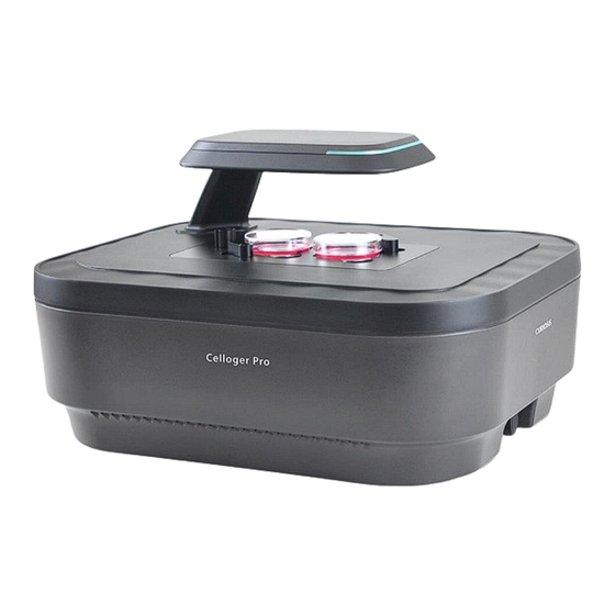
- Page 1 Automated live cell imaging system Quick Manual...
- Page 2 Table of Contents Ⅰ. Device Layout Ⅱ. Installation Ⅲ. Operation • Scan App • Analysis App Ⅳ. Specifications Ⅴ. Appendix • Z-Stacking • Stitching • IP Setting • Lens Change...
- Page 3 Device Layout...
- Page 4 Ⅰ. Device Layout Front-Left Side Illuminator (Bright field) Objective lens Indicator Vessel holder LAN port(to PC) LAN port(to Device) Power switch FRONT Power input port LAN port www.curiosis.com...
- Page 5 Installation...
- Page 6 Turn on the power switch. cable(White) to the PC. (Push the cable until you hear the clicking sound) Step 9. Check if the LED indicator illuminates yellow to confirm the Step 6. Connect the Power cable to an outlet. device's power connection status. www.curiosis.com...
- Page 7 Disconnected sign will appear.) Step 7. Choose the magnification (2X, 4X, 10X) for the objective lens installed on the device. Step 8. Click on Save to apply the changes. *Note. You can also change the magnification by referring to Appendix p.24 www.curiosis.com...
- Page 8 Place the sample on the stage of the Celloger® Pro, Make sure the A1 Step 2. Before beginning experiments, place the Celloger® Pro in an incubator of the plate and stage are aligned. for prewarming. (It is recommended to prewarm for more than 2 hours.) www.curiosis.com...
- Page 9 Operation...
- Page 10 Move to the desired position using the Jog button. (Use diagonal arrows to change the focus level (Z-coordinates).) Step 4. Adjust the brightness using the Light Source panel. (*Note. To adjust the fluorescence light level, switch the light source tab to ‘FL Green’ or ‘FL Red’) www.curiosis.com...
- Page 11 Set the focus using the Jog button( (*Note. Because the focus for fluorescence scanning can be different, it should be adjusted upon use.) Step 2. Upon finding the best focal point for scanning, designate the location by pressing Current Position in the Set Position section. www.curiosis.com...
- Page 12 3. Time Setting & Time-Lapse Imaging ① ② ③ Step 1. Click Time-lapse Run. Step 2. Enter the Interval time and Total Running Time in the schedule; other information will be set automatically. Step 3. Click Start to begin image scanning. www.curiosis.com...
- Page 13 1. Confluency & Graph ① Confluency(%) graph ② ③ Confluency(%) result Step 1. Import the time-lapse folder or the image file by pressing Step 2. Click Analyze to estimate confluency. Step 3. Click Chart to create the confluency graph. www.curiosis.com...
- Page 14 ② Step 1. Import the time-lapse folder or the image file by pressing Step 2. Click Record to create the video. *Note. To adjust the parameter(FPS: Frames per second), click on Preferences under the Tool menu. (Recommended value: 5~13) www.curiosis.com...
- Page 15 Specifications...
- Page 16 9.6 kg Culture vessels Well plate up to 96-well, flask, dish, slide File export format TIFF, AVI (JPEG, PNG) Operating environment 10~40℃, 20~95% humidity Power requirement 100-240V, ~50/60Hz O/S required Windows 10 and above Incubator specification Above 200L (recommend) www.curiosis.com...
- Page 17 Appendix...
- Page 18 Step 1. Select the position in the Scan Step 5. Set the Interval Time and Total Z-stacking function. table where the Z-stacking function will be Running Time in the schedule and scan the Step 4. Click Apply All. image. applied. www.curiosis.com...
- Page 19 Step 1. Select the position in the Scan Step 5. Set the Interval Time and Total Range. table where the stitching function will be Running Time in the schedule and scan the Step 4. Click Apply All. applied. image. www.curiosis.com...
- Page 20 Ⅴ. Appendix IP Setting Window 10 ③ ⑤ ④ Step 3. Click Network and Internet. ② Step 4. Click Ethernet. Step 5. Click Change adapter options. ① Step 1. Click the Window icon. Step 2. Click the Setting icon. www.curiosis.com...
- Page 21 Step 8. Select Use the following IP address and 4(TCP/IPv4) and click Properties. enter the IP address (192.168.2.XX) and Subnet mask (255.255.255.0) in the blank fields. *Note. Fill 2 ~ 254 except 10 in XX fields. Step 9. Click OK. www.curiosis.com...
- Page 22 Ⅴ. Appendix IP Setting Window 11 ② ④ ③ ① Step 4. Next to Ethernet, click Properties. Step 1. Click the Window icon. Step 3. Click Network and Internet. Step 2. Click the Setting icon. www.curiosis.com...
- Page 23 Next to IP assignment, click Edit to change the IP address(192.168.2.XX) and address. Subnet mask(255.255.255.0) in the blank fields. *Note. Fill in any numbers from 2~254 except 10 in fields. Step 9. Click Save, then the ⑨ network configuration is completed. Step 7. Change IPv4 to On. www.curiosis.com...
- Page 24 Step 3. Remove the objective lens by rotating it Step 5. Insert the vessel holder back into the newly installed lens and click Finish. counterclockwise and replace it with the new lens. device and click Next. Step 4. Click Next. www.curiosis.com...
- Page 25 Thank you End of Document Curiosis Inc. 4F, 10, Teheran-ro 38-gil, Gangnam-gu, Seoul 06221, South Korea T 82 2 508 5237 F 82 2 508 5246 sales@curiosis.com www.curiosis.com CRQM011-2307...
Need help?
Do you have a question about the Celloger Pro and is the answer not in the manual?
Questions and answers