Table of Contents
Advertisement
Quick Links
Advertisement
Table of Contents

Related Manuals for CURIOSIS Celloger Mini Plus


Summary of Contents for CURIOSIS Celloger Mini Plus
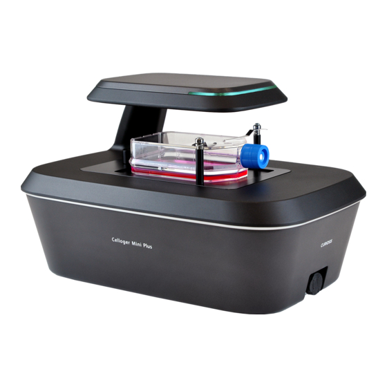
- Page 1 Automated Live Cell Imaging System Celloger® Mini Plus Instruction manual...
- Page 2 Developed and manufactured by CURIOSIS Inc. Email: info@curiosis.com Website: www.curiosis.com CURIOSIS Inc. 4F, 10 Teheran-ro 38-gil, Gangnam-gu, Seoul 06221, South Korea Tel: +82-2-508-5237 Fax: +82-2-508-5246 Copyright © 2022, by CURIOSIS Inc. All rights reserved. Published in Korea. CR-IFU-008(Rev.5) FOR RESEARCH USE ONLY and not for use in diagnostic procedures. Specifications subject to change...
-
Page 3: Table Of Contents
I. Package contents II. Device layout III. Getting started 1. Pre-requirements 2. Installation Section 1. Celloger Mini Plus Scan App I. General Operation 1. Create or open a project 2. Connect the device 3. Software overview 4. Preparation (cell/device preparation) 5. - Page 4 Trouble Shooting Product specifications Ordering Information Appendix A. Connecting multiple devices Appendix B. Alternative PC network setup Appendix C. How to use vessel editor Appendix D. How to insert vessel holder Appendix E. The list of shortcut keys...
-
Page 5: Package Contents
USB/LAN adapter LAN Cable USB memory - Instruction Manual - Celloger Mini Plus Scan App - Celloger Mini Plus Analysis App Vessel holder for well plate (Included) Vessel holder for dish 35mm, dual (Optional) Vessel holder for dish 60mm, dual (Optional) -
Page 6: Device Layout
II. Device layout Front-left side... -
Page 7: Getting Started
III. Getting started 1. Pre-requirements Installation location For normal and stable operation of the device, the following environmental conditions should be satisfied. ® Install Celloger Mini Plus on a flat and level surface away from vibrating equipment. Place in dust- and other airborne particles-free area. ... -
Page 8: Installation
Mini Plus from the box, remove all the covers, and place it on a clean and level surface. Make sure all accessories are present by checking “Package Contents” (p.5). If any items are missing or damaged, please contact your distributor or Curiosis at info@curiosis.com. 2.2 Connect the device and computer Prepare a computer that meets the specifications (refer to p.70 for PC specifications) and place it near the... - Page 9 Place the sample on the stage. Check the connection between the PC and the device. To connect the device and PC, refer to “Connect the device” (p.11). STATUS LIGHT Green Ready Scanning Blue Yellow PC disconnected Error White Identify...
-
Page 10: Section 1. Celloger Mini Plus Scan App
I. General Operation 1. Create or open a project 1. After installing Celloger® Mini Plus, execute the Celloger Mini Plus Scan App ( 2. A pop-up screen for project selection is displayed. Note. The settings for Celloger® Mini Plus can be managed using the project file (".CGPPROJ" file format). Setting values (Light intensity, Focus, Position, Schedule, File storage location, etc.) are saved in the project. -
Page 11: Connect The Device
2. Connect the device ① ② ③ 1. Open the Celloger Mini Plus Scan App ( 2. When the app is executed, the Create or Open a project popup appears. Select Continue without configuration. 3. The Connect your device popup will show. - Page 12 <Device connection pop-up description> A. Refresh Network Adapter reads the connected network adapter from the PC. B. Network adapter list. Operational Status shows the network connection status where Up means network is enabled, while Down means it is disabled. ✓ Change IPAddress: Change the IP address of selected network and device.
-
Page 13: Software Overview
3. Software overview Celloger Mini Plus Scan App is a program for the actual operation of the Celloger® Mini Plus device, which includes real-time cell monitoring and time-lapse imaging functions. Note. Refer to p.29 for full software descriptions. ⑥ ⑧... -
Page 14: Preparation (Cell/Device Preparation)
4. Preparation (cell/device preparation) ① Install the vessel holder. ② Place the Celloger® Mini Plus in the incubator. Note. Place the system as far as possible from the incubator door and place the device around 10 cm away from surroundings for proper air flow of rear cooling fan. Note. - Page 15 ③ Move to the desired scan position using the Jog button. If the display is too dark or bright, preventing the cells to be seen, run 5.2 Light intensity adjustment in p.18 first. Note. Double-clicking the mouse on the vessel image moves the lens to the center of the vessel. Additionally, double-clicking at the desired position on the vessel image while holding down the “Ctrl”...
- Page 16 ② Open Preferences in the Tool menu. ③ Designate parameters (Depth, Resolution, Offset) in the Auto Focus tab and press OK. ✓ Depth: Screening scope for autofocusing ✓ Resolution: The interval of autofocusing calculation within screening scope (0.010 mm or less for 4X optic and 0.005 mm or less for 10X optics) ✓...
- Page 17 Set FL Focus Since the focus of the FL (means fluorescence) channel may be different from that of the BF, it is recommended to set the focus position separately. ① Select the desired scan position on the Scan table. It is indicated in green once selected. ②...
- Page 18 ④ Check if the designated FL focus value is shown in Scan table. 5.2 Light intensity adjustment The light source options for the Celloger® Mini Plus is displayed on the lower tab. To adjust and customize the parameters, simply select the desired light source; the changes made are automatically saved. Given the significant impact of brightness on analysis accuracy, it is important to set the appropriate brightness level to ensure clear differentiation between cells and the background.
- Page 19 ③ Click Current Position for each position of the range you want to stack by using in the Jog. 2) Automated Z-stacking ① Select the position in the Scan table where the Z-stacking function will be applied. Scan table ② Select the channels to perform the Z-stacking function in the Z-stacking section under Properties (refer to p.40 for Z-stacking).
- Page 20 5.4 Stitching ① Select the position in the Scan table where the stitching function well be applied. Scan table ② Select the channels to perform stitching function in the Stitching section under Properties (refer to p.40 for Stitching) ③ Set the overlapping area between the images using Overlap scroll bar and designate the range to be scanned in Range.
-
Page 21: Image Analysis
6. Image analysis 6.1 Capture icon in the Toolbox captures the image on Display. (Use “Ctrl + I” as a shortcut) An image with features It is possible to generate and manipulate the image’s features, show it on Display, and save it as it is. To obtain the raw image without any manipulated features, press (Features layer) for deactivation and then press to save. - Page 22 Method 2) Local adaptive thresholding: Divide the image into local areas and thresholding is conducted by comparing relative intensity among these areas. Adjust parameters of the Kernel Size and Offset while looking at the mask of the image, with the Adaptive Algorithm box checked. (Kernel Size indicates size of local and Offset indicates the relative offset of the threshold within the local area.) Note.
- Page 23 ✓ Bad Pixel Correction: As a correction for defective pixels, the image is divided into pixels. Values that significantly stand out from a certain threshold between adjacent values are then smoothed or blurred. <Before Bad Pixel Correction> <After Bad Pixel Correction> ✓...
- Page 24 ✓ Histogram Equalization: It is a function that allows image where the histogram is concentrated in a specific area to have the histogram distributed evenly over the entire area. <Before Histogram Equalization> <After Histogram Equalization> ✓ FFC (Flat Field Correction): It is a function to uniformly correct the brightness value of the captured image. <After FFC>...
- Page 25 6.5 Preview record Upon activating Preview Record in the Tool menu, the image shown on the display is recorded and saved while streaming. The date and time of recording are displayed on the upper left corner of the recorded video. Note.
- Page 26 2) Histogram Upon selecting Histogram in the Visibility menu, an Intensity Histogram is shown on Display. 6.7 Manual Counting In the Tool menu, proceed to Manual Counting and select the Count option. To start counting, click on the desired area with the mouse. Each clicked area will show a check mark and a corresponding number. The total number of check marks/clicked area is shown at the top as the Counting Result.
-
Page 27: Time-Lapse Imaging
Experiment name in the Scan folder within the Celloger Mini Plus Scan App folder. If the experiment name is not entered, a folder will be automatically created with the date you started scanning. - Page 28 ⑦ Once the scanning is completed, check the saved images, make videos, or perform additional analysis using Celloger Mini Plus Analysis App. Note. Images are saved as merge image and raw image. A merged image combines both Brightfield (BF) and Fluorescence (FL) images, displaying scanning information such as a scale bar and scanning time.
-
Page 29: Software Description
II. Software description Upon opening the Celloger Mini Plus Scan App and completing pre-setup (refer to p.10~12), the following main page is displayed. ⑥ ⑧ ① ② ⑩ ③ ⑨ ④ ⑤ ⑦ ⑪ ① Menu bar [File] ✓ Open Project: Import a previously saved project. - Page 30 ✓ F/W Update: Update the firmware of connected device. [Help] ✓ About Celloger Mini Plus: Display app information. ② Toolbox [Preview] : Turns streaming on/off. The live image is shown based on the selected channel such as BF, FL green, and FL red the Light Source Control section of the software.
- Page 31 Preview On: When Pan is clicked and drag the screen using mouse, camera moves and shows the real-time image on the screen. Preview Off: When Pan is clicked, it works only in Zoom-in status where the camera doesn’t move and shows only the image within the display.
- Page 32 ④ Light Source Control The tabs in Light Source Control are composed of BF, FL green, and FL red. The configuration of tabs is set depending on the light options of Celloger® Mini Plus. ✓ LampPower (%): Controls the lamp (illuminator) power that is adjustable from 0 to 100 %. ✓...
- Page 33 ) can be selected. Note. The specifications of the well plates are different for each brand. On the Celloger Mini Plus Scan App, the well plate specifications are set based on a certain brand’s specifications. As such, if a well plate other than the set brands’...
- Page 34 [Plate panel] It shows the vessel selected under Vessel type as an image, and the current position of the camera on the stage (refer to p.35 for Show scan point). The image below is an example of vessels that appear on the Plate panel, and the pink dot indicates the camera’s current position.
- Page 35 ⑨ Position Control Snap to Well & Show Scan Point [Snap to Well] If checked, it moves from well to well using the arrows on the keyboard when “Num Lock” is off. It can only be used when the vessel type selected is a well plate.
- Page 36 Set Position [Default] After setting the autofocusing frequency (p.39) and fluorescence channel in Default, the set Default value is automatically applied in every set position. Note. If you want to execute the autofocusing function with a frequency other than the default at specific scan positions, you can select and change the desired position in the scan table (D).
- Page 37 ✓ Set Matrix: Set scan positions at the top, bottom, left, and right based on the current position. For example, the image below shows that positions 10 mm above, below, left, and right are designated as scan positions based on the current location. 10 mm 10 mm Position reorder...
- Page 38 ✓ Util: It is the Z-stacking or stitching value where ZS stands for Z-stacking while ST stands for stitching. In case of ZS(a, b), images are taken at intervals set in Step from top to bottom based on the Z-axis coordinates of the Focus.
- Page 39 Properties It shows the Focus, Auto focus frequency, and FL channel status of the selected position in the scan table (indicated in green). You can change to options other than the Default values and set the focus of fluorescence imaging. Furthermore, the Z-stacking and stitching settings can be adjusted after selecting whether or not to perform the Z-stacking and stitching.
- Page 40 [Z-stacking] ✓ IsEnabled: Select whether or not to run the Z-stacking function in BF and FL channels by clicking the boxes. ✓ Step: When executing the Z-stacking function, it sets the interval at which the Z-axis is to be imaged and it can be set up to 1,000 μm.
- Page 41 <Example> Scan table Properties (Stitching) In the above example, the Util value of the selects position in the Scan table is ST(2,2,2,2) and the channel and Overlap settings of Stitching in properties are BF and FL green, and 20%. This means that based on the selected position (reference position of X: 13.780, Y: 56.060), two images are captured up, down, left, and right respectively to take the total images of 25 (= 5x5) with overlapping area of 20% as shown in the image below.
- Page 42 OK. If a location is not designated, the file will be saved automatically in the Scan folder under the Celloger Mini Plus Scan App folder. The file name can be entered in the Enter Experiment Name Here before saving.
- Page 43 To go back to the original state, press Reset Layout in the Tool menu before closing the Celloger Mini Plus Scan App. When the window disappears, delete “LayoutCGP.XML” in the Celloger Mini Plus Scan App folder to go back to default state after closing the app.
- Page 44 D. Firmware version of connected device Note. If the device is not connected, shows up. Click Connect in the Device menu for reconnection. If the connection window does not show the device icon, refer to Note in p.11.
-
Page 45: Section 2. Celloger Mini Plus Analysis App
1. Create or open a config file Upon executing the Celloger Mini Plus Analysis App, a pop-up screen for project selection appears. With Celloger® Mini Plus, the setting can be managed with the config file (“.CGPPROJ” file format). Setting parameters, including Adjust, Coverage, Preferences, etc. -
Page 46: Software Overview
2. Software overview Celloger Mini Plus Analysis App is a program dedicated to analyzing and post-processing images captured with Celloger® Mini Plus. This software can be operated without requiring a connection to the device. Note. Refer to p.61 for full software descriptions. -
Page 47: Import The Data
② Drag the time-lapse folder or image file. Note. In order for the file to be correctly imported into the Celloger Mini Plus Analysis App, the file name and location address should consist only of English letters, numbers, and some special symbols (avoiding characters such as /, :, *, ?, <, >, |). -
Page 48: Data Analysis
II. Data analysis 1. Merge the FL image Press (Merge layer) for activation, which is displayed as , and select the merge method ( ). The merged image will be shown Display. ① (Alpha Blending): A method of combining images with a transparent effect. Individual color channels are presented in separate layers, and the merged image is displayed by combining the information from each layer with adjusted opacity. -
Page 49: Slide Show
the image mask after checking the Adaptive Algorithm box. (Kernel Size indicates the size of local area and Offset indicates the relative threshold offset of the local area.) Note. When the fluorescence areas are distorted or clustered in one place, Global thresholding function is recommended;... -
Page 50: Estimate Coverage
Note. To change the FPS, adjust the parameter in Preferences of the Tool menu (Recommended value: 5 ~ 13). Estimate coverage Celloger® Mini Plus’ coverage analysis is divided into three modes: Normal cell, Spheroid cell, and Wound area. Normal cell and Wound area show coverage result in “%”, and Spheroid cell shows it in “mm ”. - Page 51 ⑤ The coverage values and coverage mask (yellow) are indicated as shown below. Selecting a cycle from the list allows you to view the corresponding cycle's image and coverage mask. Coverage result <Calculated coverage values and coverage mask> Note. You can change the coverage parameters in Preferences of the Tool menu.
- Page 52 Note. If you want to adjust the coverage masking color or transparency, select Preferences under the Tool menu, change the parameters in Analysis under Merge Layer and click Apply. Note. If you do not want to see the coverage mask, deactivate it by clicking on under Toolbox.
-
Page 53: Create Coverage Graph
5. Create coverage graph ① Open the time-lapse folder or images captured with the Celloger Mini Plus Scan App and press Analyze. ② Press Chart to create the coverage graph. ③ Select Coverage in the Information column. ④ Select whether to create graph from scan positions (= Point) or well averages (= Well) and the light channel in the Information column. -
Page 54: Show Z-Stacking Image
6. Show Z-stacking image ① Open the time-lapse folder or images captured with the Z-stacking function. ② After selecting the scan position with Z-stacked images, click the Z-stacking tab to see the Z-stacking list. The image below shows the Z-stacking list when the Range of Z-stacking function is set to ZS(-5,5). ③... -
Page 55: Merge Z-Stacking Images (Intensity Z-Projection)
Note. If you want to make a video of the images in the Z-stacking list, ① Check the Z-stacking checkbox above the Z-stacking list and ② Click Record. The video appears in the order of the Z-stacking list (from low to high focus). The FPS of the video can be adjusted in Properties of the Tool menu (p.50). ②... -
Page 56: Stitch Images
8. Stitch images ① Open the time-lapse folder or images captured with the stitching function. ② After selecting the scan position with stitching function, click the Stitching tab located on the right side of the analysis software to see the Stitching position. The image below shows the Stitching position when the Range of stitching is set to ST(1,1,1,1). -
Page 57: Image Adjustment
Note. When stitching is completed, images are saved in the stitching folder created in the raw image folder. Note. Clicking View opens the stitched image file. 9. Image adjustment Adjust the image using parameters (Kernel size, brightness, contrast, gamma) in Adjust in the Tool menu, and save the modified image. - Page 58 ✓ Bad Pixel Correction: As a correction for defective pixels, the image is divided into pixels. Values that significantly stand out from a certain threshold between adjacent values are then smoothed or blurred. <Before Bad Pixel Correction> <After Bad Pixel Correction> ✓...
-
Page 59: Intensity
✓ Histogram Equalization: It is a function that allows image where the histogram is concentrated in a specific area to have the histogram distributed evenly over the entire area. <Before Histogram Equalization> <After Histogram Equalization> ✓ FFC (Flat Field Correction): It is a function to uniformly correct the brightness value of the captured image. -
Page 60: Manual Counting
11. Manual Counting ① Click Manual Counting in the Visibility menu. Then, his will generate the Manual Count section in the Toolbox. ② Click Count in the Manual Count section or proceed to Manual Counting and select Count option in the Tool menu. -
Page 61: Software Description
III. Software description Upon opening the Celloger Mini Plus Analysis App and completing pre-setup (refer to p.45), the following main page is displayed. ① ② ③ ⑤ ④ ① Menu bar [File] ✓ Open Config: Import a previously saved config file. - Page 62 [Tool] ✓ Manual Counting (p.60): Count the points clicked by user. ① Count: Add a point for counting. ② Remove: Delete a clicked point. ③ Clear: Delete all points. ✓ Reset Layout (refer to Note in p.63): Restore the software layout to its original state before any modifications.
- Page 63 To go back to the original state, press Reset Layout in the Tool menu before closing the app. When the window disappears, delete the “LayoutCGP.XML” file in the Celloger Mini Plus Analysis App folder to go back to default state after closing the app.
- Page 64 Click to load the image file taken with the Celloger® Mini Plus (refer to p.47). Analyze images or make time-lapse videos. ✓ Analyze: Calculate the coverage of the files checked on the list. ✓ Chart: Show the coverage graph and intensity graph (refer to p.53).
- Page 65 Point/Well: Choose either a point or well to create the graph. Choosing a point shows the graph for each scan position, while selecting a well shows the graph of the average value for that specific well. <Well> <Point > BF/FLGreen/FLRed: Choose the light channel to create the graph. Coverage/Intensity: Choose whether to make a coverage graph or an intensity graph.
-
Page 66: Safety Instruction
Install the device on a rigid and level place. Operate the device in conditions described in the operating condition section below. Use only the components provided and authorized by Curiosis Inc. Ensure the input voltage matches with the device’s power supply voltage. -
Page 67: Safety Standards
Safety standards European standards US standards UK Standards Korean standards ROHS Cleaning and Maintenance When cleaning optical elements, use only a damp cloth to avoid scratching soft lens coatings. Do not clean the lens with organic solvents. Lightly wipe the working surfaces of the Celloger® Mini Plus with a soft cloth dampened with 70% ethanol or hydrogen peroxide (H ). -
Page 68: Trouble Shooting
✓ Replace power cable if it is in poor condition. Cannot connect with Celloger® Mini Plus device ✓ Make sure the device is connected to the computer. ✓ Unplug and re-connect all cables. Restart the Celloger Mini Plus Scan App. Focus Focus is irregular ✓... - Page 69 Data Cannot play the video ✓ Video can be made only for time-lapse images obtained from the Celloger Mini Plus Scan App. Cannot analyze the coverage ✓ Check if the images are obtained from the Celloger Mini Plus Scan App.
-
Page 70: Product Specifications
Product specifications Dimension 226 x 358 x 215 mm Weight 5.6kg / 12.3lb Objective Lens 2X / 4X / 10X Imaging modes Brightfield, Fluorescence (Green/Red) Green : Excitation (470/40x) / Emission (510lp) Fluorescence Red: Excitation (510/84x) / Emission (570lp) Light source Camera 5.0 MP CMOS Focus... -
Page 71: Ordering Information
Ordering Information Cat. No. Description CRCLG-MPB02 Celloger® Mini Plus, Live cell imaging system (Bright Field, 2X) CRCLG-MPB04 Celloger® Mini Plus, Live cell imaging system (Bright Field, 4X) CRCLG-MPB10 Celloger® Mini Plus, Live cell imaging system (Bright Field, 10X) CRCLG-MPBG04 Celloger® Mini Plus, Live cell imaging system (Bright Field + Green Fluorescence, 4X) CRCLG-MPBG10 Celloger®... -
Page 72: Appendix A. Connecting Multiple Devices
To connect multiple Celloger® Mini Plus units with the same IP address, it is necessary to set the IP address of the devices. The Celloger Mini Plus Scan App can be used to change the IP address of a device. - Page 73 192.168.2.12 Note. When setting the IP address of the network adapter in the Celloger Mini Plus Scan App, only one of two or more devices must be checked in the DHCP Server and other devices must be unchecked. In case of setting the IP manually on a PC (p.75), connection can be done regardless of the DHCP Server.
- Page 74 PoE injecto PoE injecto Celloger® Mini Pl 2. Operation ① Open the Celloger Mini Plus Scan App after completing network setup. ② Select the device and connect it. ① ② Note. Devices connected to the app can be identified by choosing one of methods below: Check the selected device description.
-
Page 75: Appendix B. Alternative Pc Network Setup
⑨ Click “OK”, then the network configuration is completed. ⑩ To start the Celloger Mini Plus Scan App, first, connect the USB drive provided with device into the PC, then copy the app folder to PC and execute “Celloger Mini Plus Scan App.exe” in the app folder. - Page 76 < Image Descriptions of PC network setting > 1) Window 10 ③ ② ① ⑤ ④ ⑥ Mouse right button click...
- Page 77 ⑧ ⑦ ⑨ 2) Window 11 ② ③ ① Properties ④ Properties...
- Page 78 ⑥ ⑤ ⑦ ⑧ ⑨...
-
Page 79: Appendix C. How To Use Vessel Editor
Appendix C. How to use vessel editor The Celloger® Mini Plus’s well plate specifications are set based on a certain brand’s specifications. As the specifications of the well plate differ for each brand, imaging may be difficult when the well plate you are using doesn’t match the default well plate specification in Vessel type. - Page 80 ④ Click on Refresh. ⑤ Click on Export to save the setting values. The saved file can be found in the “Vessel” folder of the Celloger Mini Plus Scan App. ⑥ Re-run the Celloger Mini Plus Scan App. ⑦ After checking if there is a well plate of the brand saved in...
-
Page 81: Appendix D. How To Insert Vessel Holder
Appendix D. How to insert vessel holder Select the holder suitable for the vessel type. As shown in the figure below, insert the tip of holder to the area where it faces the LAN port of the device first and mount it. Insert the screw into the hole and turn it clockwise to assemble. Caution! Please be careful when tightening the screw. -
Page 82: Appendix E. The List Of Shortcut Keys
Appendix E. The list of shortcut keys Save the image Save the project Move to the double-clicked position Mouse double click Zoom in & out Mouse wheel When in Preview on state, camera moves according to drag. Mouse drag The camera moves so that the double-clicked location becomes the center of the screen. - Page 83 Revision History Date Version Description CR-IFU-008 Initial issue 2022/03/03 CR-IFU-008(Rev.1) 2022/06/09 - Revised contents (Operating condition) - Added contents (Grid line, Image adjustment, Preview record, Stitching, Chart) - Revised contents (Table of contents, Getting started, Z-stacking, CR-IFU-008(Rev.2) 2022/09/15 Image analysis control, Autofocus, Cleaning and Maintenance, Troubleshooting, Appendix B) - Revised UI (Image analysis control) CR-IFU-008(Rev.3)
- Page 84 Curiosis Inc. HEADQUARTERS 4F, 10 Teheran-ro 38-gil Gangnam-gu, Seoul 06221 South Korea TEL +82-2-508-5237 FAX +82-2-508-5246 Email: info@curiosis.com FACTORY 400, Wonam-ro, Namsa-eup Cheoin-gu, Yongin-si, Gyeonggi-do 17123 South Korea TEL +82-31-339-6404 FAX +82-31-339-6409 www.curiosis.com...
Need help?
Do you have a question about the Celloger Mini Plus and is the answer not in the manual?
Questions and answers