Table of Contents
Advertisement
Quick Links
Advertisement
Table of Contents

Related Manuals for CURIOSIS Celloger Mini Plus


Summary of Contents for CURIOSIS Celloger Mini Plus
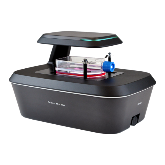
- Page 1 Celloger® Mini Plus Automated live cell imaging system Instruction Manual...
- Page 2 Developed and manufactured by CURIOSIS Inc. Email: info@curiosis.com Website: www.curiosis.com CURIOSIS Inc. 4F, 10 Teheran-ro 38-gil, Gangnam-gu, Seoul 06221, South Korea Tel: +82-2-508-5237 Fax: +82-2-508-5246 Copyright © 2022, by CURIOSIS Inc. All rights reserved. Published in Korea. CR-IFU-008(Rev.2) FOR RESEARCH USE ONLY and not for use in diagnostic procedures. Specifications subject to change without...
-
Page 3: Table Of Contents
3. Installation 4. Create or open a project 5. Connect the device 6. Software overview 6.1. Celloger Mini Plus Scan App 6.2. Celloger Mini Plus Analysis App IV. General operation 1. Preparation (cell/device preparation) 2. Cell monitoring and image setting [in Scan App] 2.1 Location adjustment... -
Page 4: Package Contents
• Check that all items listed above are included in your package. • Examine the device carefully for any damage during shipping. • Contact your local distributor or info@curiosis.com if any items are missing or damaged. • Any loss or damage claims must be filed with the carrier. -
Page 5: Device Layout
II. Device layout... -
Page 6: Getting Started
III. Getting started 1. Pre-requirements Installation location For normal and stable operation of the device, the following environmental conditions should be satisfied. Install Celloger® Mini Plus on a flat and level surface away from vibrating equipment. Place at dust- or other airborne particles-free area. ... -
Page 7: Installation
2. Make sure all accessories are present by checking “Package Contents” (p.4). If any items are missing or damaged, please contact your distributor or Curiosis at info@curiosis.com. Connect the device and computer 1. Prepare a computer that satisfies the specifications (refer to p.55 for PC specifications) and place it near the incubator. -
Page 8: Create Or Open A Project
Celloger Mini Plus, the setting can be managed by the porject file (“.cgnproj” file format). Setting values(Light intensity, Focus position, Schedule, File storage location, etc.) are saved in the project. Note. In Celloger Mini Plus Analysis App, the setting is managed by config file instead of project file. Import the project saved in the past. -
Page 9: Connect The Device
② ③ ④ 1. Open Celloger Mini Plus Scan App. 2. When the app is executed, Create or Open a project popup appears. Select Continue without configuration. 3. Connect your device popup will show. 4. Click Get Network Adapter to load the network adapters connected to the PC. - Page 10 Set the IP address of PC network manually. If the PC IP, device IP and router IP are the same, connection fails (refer to Appendix B). Case 2. LAN or power cable is not connected properly (LED status indicator is turned off.). Check all cable connection status and POE injector power (refer to Connect the device and computer in p.7).
-
Page 11: Software Overview
Celloger® Mini Plus provides two software: Celloger Mini Plus Scan App and Celloger Mini Plus Analysis App. Celloger Mini Plus Scan App is a program for actual operation of Celloger® Mini Plus device which includes real- time cell monitoring and time-lapse imaging function. Celloger Mini Plus Analysis App is a program for analyzing and post-processing the images obtained from Caloyer®... -
Page 12: Celloger Mini Plus Analysis App
6.2. Celloger Mini Plus Analysis App ① ② ③ ⑤ ④ ① Menu bar ② Toolbox ③ Display ④ Light source control & Z coordinates ⑤ Image analysis control... -
Page 13: General Operation
IV. General Operation 1. Preparation (cell/device preparation) The cell preparation method is different depending on the type of assay. The method below is a general process recommended for the monitoring of cells. 1. Before culturing the cell, place Celloger® Mini Plus in the incubator for prewarming. Note. - Page 14 ② Press Preview for streaming while BF is selected in the Light Source Control. ③ Move to the desired scan position using the Jog button. If the display is too dark or bright, preventing the cells to be seen, run 2.2 Light intensity adjustment in p.17 first. 2) Set BF Focus ➢...
- Page 15 ② Open Preferences in the Tool menu. ③ Designate parameter (Depth, Resolution, Offset) in the Auto Focus and press OK. ✓ Depth: Screening scope for autofocusing ✓ Resolution: The interval of autofocusing calculation within screening scope (0.010 mm or less for 4X optic and 0.005 mm or less for 10X optics) ✓...
- Page 16 3) Set FL Focus Offset Since the focus of the FL channel may be different from that of the BF, it is recommended to set the focus position separately. ① Select the desired scan position on the Scan table. It is indicated in green once selected. ②...
-
Page 17: Light Intensity Adjustment
2.2 Light intensity adjustment Light source option for Celloger® Mini Plus is displayed on the lower tab. Select the desired light source to adjust and change the parameter. It is automatically saved. Brightness is one of the important factors that has an impact on analysis accuracy. -
Page 18: Stitching
Properties (Z-Stacking) ④ After clicking Apply All, check that the set z-stacking value appears in Util. 2.4 Stitching ① Select the position in the scan table where the stitching function will be applied. Scan table ② Select whether or not to execute the stitching function in BF and FL in Stitching under Properties. (refer to p.46 for Stitching) ③... -
Page 19: Image Analysis [In Scan App]
④ After clicking Apply All, check that the set stitching value appears in Util. Note. When stitching is performed under autofocus and fluorescence setup, be reminded that it takes approximately 2 minutes to scan 3 x 3, and 7 minutes and 30 seconds to scan 7 x 7 with the light conditions of BF (Lamp: 30, Exposure: 0.06, Gain: 1) FL (Lamp: 30, Exposure: 0.5, Gain:1). -
Page 20: Merge Image
3.2 Merge image Press (Merge layer) for activation , merged image is shown on Display. Adjusted image as follows can be obtained upon changing Merge Layer setting (Opacity and Threshold) in Preferences of Tool menu. Celloger® Mini Plus conducts thresholding for FL channel image based on intensity and merge it with BF image. -
Page 21: Image Adjustment
3.4 Image adjustment Adjust the image using parameters (Kernel size, brightness, contrast, gamma) in Adjust in Tool menu, and save the modified image. Before adjustment After adjustment Note. In case of fluorescence as shown in the image below, Bad Pixel Correction and Brightness & Contrast are set by default, therefore it should be adjusted. -
Page 22: Preview Record
3.5 Preview record Upon activating Preview Record in Tool menu, the image shown on the display is recorded and saved while streaming. The date and time of recording are displayed on the upper left of the recorded video. Note. When Preview Record is activated, recording continues even Preview is turned off and on. To end the recording, you must deactivate it in Preview Record. -
Page 23: Manual Counting
2) Histogram Upon selecting Histogram in Visibility menu, Intensity Histogram is shown on Display. 3.7 Manual Counting Select Count in Manual Counting in Tool menu and click the desired area to count with cursor, clicked area is checked and the counted number is shown in Counting Result. To delete part of the result, press Remove and click the items to be deleted. -
Page 24: Time-Lapse Imaging [In Scan App]
④ Open Time-lapse Control and select the location to save and enter the project name. If the image storage location is not specified, the file will be saved in the Scan folder under the Celloger Mini Plus Scan App folder and if the project name is not entered, a folder will be automatically created under the scan start date. -
Page 25: Process Single Image Or Time-Lapse Images [In Analysis App]
5. Process single image or time-lapse images [in Analysis App] It is possible to conduct confluency analysis and make videos in Celloger Mini Plus Analysis App using time- lapse images taken by Celloger® Mini Plus. In addition, intensity measurement, length measurement and manual counting are available in Cellger Mini Plus Analysis App and the methods are same as Celloger Mini Plus Scan App. -
Page 26: Merge Fl Image
(a file name shouldn’t contain any of the following characters: /, :, *, ?, “, <, >, |) to import the file correctly in Celloger Mini Plus Analysis App. If it fails to import the file, check whether the file name and location address is written in languages other than English. -
Page 27: Make Video
② Select the light channel ( ) or press Merge Layers ( ③ Press Play ( Note. In order to change the speed, change the FPS in Preferences of Tool menu. Note. FPS is a parameter indicating the speed of slide show and video. However, the speed of slide show and video could be different even with the same FPS. - Page 28 parameter. Therefore, to accurately calculate the coverage of fluorescence area, adjust the appropriate thresholding parameters (refer to p.20) before executing the coverage analysis. ③ Confluency values and confluency mask (yellow) are indicated. When a cycle is selected from the list, the corresponding cycle’s image and confluency mask can be seen. <Calculated confluency values and confluency mask>...
-
Page 29: Create Confluency Graph
5.6 Create confluency graph ① Open the file and images captured with Celloger® Mini Plus and press Analyze to analyze the confluency. ② Create the confluency graph by pressing Chart. Note. If you want to create the confluency graphs of only some positions from the scan position list, check the desired position and press Chart. - Page 30 ③ Select one from the Z-stacking list and check the image on Display. For example, the image below shows that the second image in Scan Positions, the third cycle in Images, and “ZStacking-2” are selected in the Z-stacking list. In this case, you can see the “ZStacking-2” image of the third cycle captured at the second scan position on Display.
-
Page 31: Stitch Images
5.8 Stitch images ① Open the time-lapse file or images captured with stitching function. ② After selecting the scan position with stitching images, click the Stitching tab under Image Analysis Control to see the Stitching list. The image below shows the Stitching list when the Range of stitching function is set to (1,1,1,1). - Page 32 ③ Select one from the Stitching list and check the image on Display. For example, the image below “Stitching1_-1” is selected in the fourth cycle of the first Scan Positions. In this case, you can see the “Stitching1_-1” image of the fourth cycle captured at the first scan position on Display. “Stitching1_- 1”...
- Page 33 ④ Click Stitching under the Stitching list to stitch the captured images. When stitching is completed, ViewChange is activated, and Success is displayed in the Result. When ViewChange is clicked, stitched image appears on the Display. Note. When stitching fails, Fail appears in the Result. ⑤...
-
Page 34: Separate The Image
5.9 Separate the image Celloger Mini Plus Scan App stores images by stacking them with raw images when the scan is performed with Fluorescence, Z-stacking, and Stitching. Using Separate function, stacked images are converted and saved as individual image files. When Separate is selected from Folder/File tab, the raw images (BF, FL) of the reference position is separated and saved. -
Page 35: Software Description
V. Software description 1) Celloger Mini Plus Scan App Upon opening Celloger Mini Plus Scan App and completing pre-setup (refer to p.8~10), the following main page is displayed. ⑥ ⑧ ① ② ⑩ ③ ⑨ ④ ⑤ ⑦ ⑪ ① Menu Bar [File] ✓... - Page 36 [Tool] ✓ Manual Counting (p.23): Count the points clicked by user. ① Count: Add a point for counting. ② Remove: Delete a clicked point. ③ Clear: Delete all points. ✓ Adjust (p.21): Adjust image ✓ Preview record (p.22): Record the streaming image ✓...
- Page 37 ✓ : Pan Preview ON: When Pan is clicked and drag the screen using mouse, camera moves and shows the real- time image on the screen. Preview OFF: When Pan is clicked, it works only in Zoom-in status where the camera doesn’t move and shows only the image within the display.
- Page 38 ✓ LampPower (%): Controls the lamp (illuminator) power that is adjustable from 0 to 100 %. ✓ Exposure (second): The duration of exposure of cells to light, adjustable from 0.01 to 2 seconds. Be careful as photobleaching occurs when exposure value is high. ✓...
- Page 39 ) can be selected. Note. The specifications of the well plates are different for each brand. On the Celloger Mini Plus Scan app, the well plate specifications are set based on a certain brand’s specifications. As such, if a well plate other than the set brands’...
- Page 40 [Plate panel] It shows the vessel selected under Vessel type as an image, and the current position of the camera on the stage (refer to p.42 for Show Scan Point). The image below is an example of vessels that appear on the Plate panel, and the pink dot indicates the camera’s current position.
- Page 41 ⑨ Position Control...
- Page 42 A. Snap to Well & Show Scan Point [Snap to Well] If checked, it moves from well to well using the arrows on the keyboard when ‘Num Lock’ is off. It can only be used when the vessel type selected is a well plate. [Show Scan Point] If checked, the position specified for scanning is indicated on the Plate panel as shown in the image below.
- Page 43 Note. When the vessel type selected is a well plate, it is possible to select a specific well from the plate panel (Ctrl + C) and apply the scan positions to aother wells (Ctrl + V). As shown in the image below, the selected wll is displayed in purple and the other wells to which the scan positions are applied are displayed in light blue.
- Page 44 FL channel: shows the focus difference from BF channel. When FL channel has lower focus than BF channel, ‘ – ‘ is added, ‘0.000’ appears when with same focus, and only numbers are displayed when FL channel has higher focus than that of BF channel. ✓...
- Page 45 D. Properties It shows the Focus, Auto Focus Frequency, and FL mode status of the selected position in the scan table (indicated in green). You can change to options other than the Default values and set the focus of fluorescence imaging (= if checked in the FL mode). Furthermore, the z-stacking settings can be adjusted after selecting whether or not to perform the z-stacking.
- Page 46 ➢ Z-Stacking ✓ : Select whether or not to run the z-stacking function in BF and FL by checking the boxes. ✓ Step: When executing the z-stacking function, it sets the interval of the z-axis to be imaged and it can be set up to 1,000 um. ✓...
- Page 47 Example Scan table Properties (Stitching) In the above figure, the Util of the location selected in the Scan table is ST (2,2,2,2) and the Overlap set in Properties is 20%. This means that based on the selected position (reference position of X: 11.200, Y: 68.300), two images are taken up, down, left, and right respectively to take the total images of 25 (5x5) with overlapping area of 20% as shown in the image below.
- Page 48 Scan Location and if a location is not designated, the file will be saved automatically in the Scan folder under the Celloger Mini Plus Scan App folder. The file name can be entered in the Enter Experiment Name Here field before saving. If a file name is not entered, the file will be automatically saved as the start time of the scan settings.
- Page 49 To go back to the original state, press Reset Layout in Tool menu before closing the Celloger Mini Plus Scan App. When the window disappears, delete “LayoutCGP.XML” in the Celloger Mini Plus Scan App folder to go back to default state after closing the App.
-
Page 50: Celloger Mini Plus Anaysis App
Upon opening Celloger Mini Plus Analysis App and selecting Config file, the following main page is displayed. * Config file: It is a file that pops up when Celloger Mini Plus Analysis App starts. It is for saving and managing parameters set in the Preferences of Tool menu. - Page 51 (Ruler), Intensity, Manual Counting can be performed on the screen. ④ Light Source Control & Z coordinates Display the light source settings and Z coordinates of Celloger Mini Plus Scan App and it cannot be changed. ⑤ Image Analysis Control Upon importing a folder, file list is displayed.
-
Page 52: Safety Instruction
D. Scan positions: In Folder/File tab , the scan positions specified in Celloger Mini Plus Scan App are shown in order as well as the X and Y coordinates of those positions. Images: In Folder/File tab , it is the cycles of selected scan positions. The image of selected cycle is shown on the display. -
Page 53: Operating Condition
2. Operating condition Operating power 100~240 VAC Electrical input 48 VDC, 1.04 A Frequency ~50/60Hz Operating temperature 10~40℃ Relative humidity 20~95% Installation site Indoor use only 3. Safety standards European standards US standards UK Standards Korean standards VII. Cleaning and Maintenance ... -
Page 54: Troubleshooting
✓ Video can be made only for time-lapse images obtained from Celloger Mini Plus Scan App. Cannot analyze the confluency ✓ Check if the images are obtained from Celloger Mini Plus Scan App; Analysis can be performed only with the images obtained from Celloger Mini Plus Scan App. -
Page 55: Product Specifications
Others Water droplets form on the well plate, dish lid or top of the flask (= Condensation occurs) ✓ Warm up the device 30 minutes before start monitoring. ✓ Check for and remove any condensation on the lid of the culture dish. (In order to prevent condensation from occurring, it is better to warm up the plate or dish lid slightly when preparing the sample.) ✓... -
Page 56: Ordering Information
X. Ordering information Celloger® Mini Plus Cat. No. Description CRCLG-MPB04 CLG Mini Plus, Live cell imaging system (Bright Field, 4X) CRCLG-MPB10 CLG Mini Plus, Live cell imaging system (Bright Field, 10X) CRCLG-MPBG04 CLG Mini Plus, Live cell imaging system (Bright Field+Green Fluorescence, 4X) CRCLG-MPBG10 CLG Mini Plus, Live cell imaging system (Bright Field+Green Fluorescence, 10X) CRCLG-MPBR04... -
Page 57: Appendix A. Connecting Multiple Devices
In order to connect multiple Celloger® Mini Plus units with the same IP address, it is necessary to change the IP address of the devices. It is possible to change the IP address of a device in Celloger Mini Plus Scan App. - Page 58 192.168.2.20 Note. When setting the IP address of the network adapter in Celloger Mini Plus Scan App (p. 9), only one of two or more devices must be checked in the DHCP Server and the other devices must be unchecked. In case of setting the IP manually on PC (p.
-
Page 59: Using A Router
PoE injector PoE injector PoE injector 2. Operation ① Open Celloger Mini Plus Scan App after completing network setup. ② Select the device and connect it. ① ② Note. Devices connected to the App can be identified by choosing one of methods below: 1) Check the selected device description. -
Page 60: Appendix B. Alternative Pc Network Setup
⑨ Click “OK”, then network configuration is completed. ⑩ To start Celloger Mini Plus Scan App, first, connect the USB drive provided with device into the PC, then copy APP folder to PC and execute “Celloger Mini Plus Scan App.exe” in the App folder. - Page 61 Image descriptions of PC network setting 1) Window 10 ③ ② ① ⑤ ④ Mouse right button click ⑥...
- Page 62 ⑧ ⑦ ⑨ 2) Window 11 ② ③ ① Properties ④ Properties...
- Page 63 ⑥ ⑤ ⑧ ⑦ ⑨...
-
Page 64: Appendix C. How To Use Vessel Editor
Appendix C. How to use vessel editor The Celloger® Mini Plus well plate specifications are set based on a certain brand’s specifications. As the specifications of the well plate differ for each brand, imaging may be difficult when the well plate you are using doesn’t match the default well plate specification in vessel type. - Page 65 ⑤ Click on Export to save the setting values. The saved file can be found in the Vessel folder of the Celloger Mini Plus Scan App. ⑥ Re-run the Celloger Mini Plus Scan App. ⑦ After checking if there is a well plate of the brand saved in Vessel Type, click on it to use it.
-
Page 66: Appendix D. How To Insert Vessel Holder
Appendix D. How to insert vessel holder Select the holder suitable for the vessel type. As shown in the figure below, insert the tip of holder to the area where it faces the LAN port of the device first and mount it. Insert the screw into the hole and turn it clockwise to assemble. - Page 67 Revision History Date Version Description 2022/03/03 CR-IFU-008 Initial issue 2022/09/15 - Added contents (Grid line, Image adjustment, Preview record, CR-IFU-008(Rev.2) Stitching, Chart) - Revised contents (Table of contents, Getting started, Z-stacking, Image analysis control, Autofocus, Cleaning and Maintenance, Troubleshooting, Appendix B) - Revised UI (Image analysis control)
- Page 68 Curiosis Inc. HEADQUARTERS 4F, 10 Teheran-ro 38-gil Gangnam-gu, Seoul 06221 South Korea TEL +82-2-508-5237 FAX +82-2-508-5246 Email: info@curiosis.com FACTORY 400 Wonam-ro, Namsa-eub Cheoin-gu, Yongin-si, Gyeonggi-do 17123 South Korea TEL +82-31-339-6404 FAX +82-31-339-6409 www.curiosis.com...
Need help?
Do you have a question about the Celloger Mini Plus and is the answer not in the manual?
Questions and answers