Table of Contents
Advertisement
Quick Links
CY8CPROTO-040T PSoC
Prototyping Kit guide
About this document
Scope and purpose
This guide helps you get acquainted with the CY8CPROTO-040T PSoC
document explains the kit operation, describes the out-of-the-box (OOB) example and its operation, and the
hardware details of the board.
Intended audience
This kit is intended for all technical specialists familiar with PSoC
Note:
Use this kit under laboratory conditions.
User guide
www.infineon.com
Arrow.com.
Downloaded from
Please read the sections "Important notice" and "Warnings" at the end of this document
4000T CAPSENSE
™
4000T CAPSENSE
™
4 MCU and CAPSENSE
™
™
Prototyping Kit. The
™
.
™
002-38600 Rev. **
2023-11-29
Advertisement
Table of Contents

Related Manuals for Infineon CY8CPROTO-040T


Summary of Contents for Infineon CY8CPROTO-040T
-
Page 1: About This Document
™ ™ Prototyping Kit guide About this document Scope and purpose This guide helps you get acquainted with the CY8CPROTO-040T PSoC 4000T CAPSENSE Prototyping Kit. The ™ ™ document explains the kit operation, describes the out-of-the-box (OOB) example and its operation, and the hardware details of the board. -
Page 2: Important Notice
Boards provided by Infineon Technologies. The design of the Evaluation Boards and Reference Boards has been tested by Infineon Technologies only as described in this document. The design is not qualified in terms of safety requirements, manufacturing and operation over the entire operating temperature range or lifetime. -
Page 3: Safety Precautions
CY8CPROTO-040T PSoC 4000T CAPSENSE Prototyping Kit guide ™ ™ Safety precautions Safety precautions Note: Please note the following warnings regarding the hazards associated with development systems Table 1 Safety precautions Caution: The evaluation or reference board contains parts and assemblies sensitive to electrostatic discharge (ESD). -
Page 4: Table Of Contents
User button ................34 CY8CPROTO-040T kit rework for evaluating additional features ......35 3.3.1... - Page 5 CY8CPROTO-040T PSoC 4000T CAPSENSE Prototyping Kit guide ™ ™ Table of contents Revision history ...............40 Disclaimer .
-
Page 6: Introduction
ModusToolbox software ™ ™ ™ a set of tools that enables you to integrate Infineon devices into your existing development methodology. If you are new to PSoC 4 and ModusToolbox software IDE, see the application note AN79953 - Getting started ™... -
Page 7: Kit Contents
™ Figure 2 CY8CPROTO-040T PSoC 4000T CAPSENSE Prototyping Kit Quick start guide ™ ™ Inspect the kit’s contents; if you find any part missing, go to Infineon's Support page for assistance. User guide 002-38600 Rev. ** 2023-11-29 Arrow.com. Downloaded from... -
Page 8: Getting Started
AN79953 - Getting started with PSoC under “PSoC 4 software resources” ™ ™ Additional learning resources Infineon provides a wealth of data in the PSoC 4 product webpage to help you to select the suitable PSoC ™ ™ device for your design and to help you quickly and effectively integrate the device into your design. - Page 9 CY8CPROTO-040T PSoC 4000T CAPSENSE Prototyping Kit guide ™ ™ 1 Introduction Table 2 (continued) Document conventions for guides Convention Usage Bold Displays commands, menu paths, and icon names in procedures: Click the File icon and then click Open. Times New Roman...
-
Page 10: Kit Operation
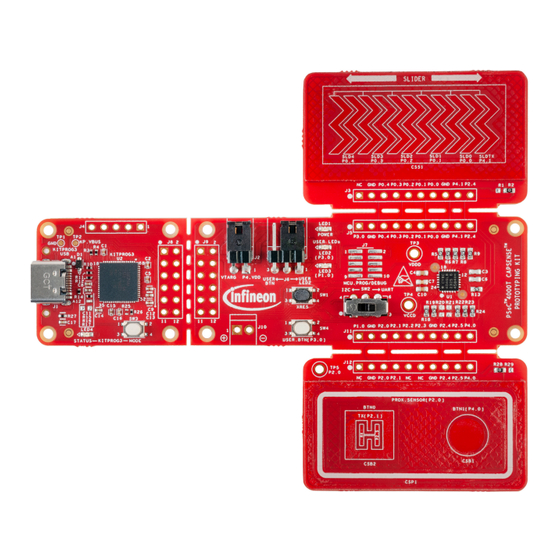
HW ID 0x03 Proximity Slide Sensor Switch UART UART (DPDT) 5-Segment Slider Voltage KitProg3 Monitoring HW ID Headers Figure 4 Functional block diagram of CY8CPROTO-040T PSoC 4000T CAPSENSE Prototyping ™ ™ Board User guide 002-38600 Rev. ** 2023-11-29 Arrow.com. Downloaded from... - Page 11 CY8CPROTO-040T PSoC 4000T CAPSENSE Prototyping Kit guide ™ ™ 2 Kit operation Figure 5 PSoC 4000T CAPSENSE Prototyping Board top view ™ ™ PSoC 4000T CAPSENSE Prototyping Kit focuses on demonstrating the capabilities of 5th-generation ™ ™ CAPSENSE technology like low power operation with always-on sensing, and improved touch sensing ™...
- Page 12 ™ ™ (CSS1) both self-capacitance (CSD) and mutual-capacitance (CSX) operation, allow you to evaluate Infineon’s fifth-generation CAPSENSE technology. The slider have a 1-mm acrylic ™ overlay for smooth touch sensing. USER LED's (LED2, LED3) The user LED’s can operate at the entire operating voltage...
-
Page 13: Using The Oob Example - Ce238817
™ Note: At any point in time, if you overwrite the OOB example, you can restore it by programming the PSoC 4: CY8CPROTO-040T demo code example. See Creating a project and program/debug using ™ ModusToolbox software for programming the board. - Page 14 CY8CPROTO-040T PSoC 4000T CAPSENSE Prototyping Kit guide ™ ™ 2 Kit operation Figure 6 Connect the USB cable to the USB connector on the board Touch the self-capacitance-based button(CSB1) or the mutual-capacitance-based button(CSB2) with the finger and observe the LED2 turns ON, as shown in...
- Page 15 CY8CPROTO-040T PSoC 4000T CAPSENSE Prototyping Kit guide ™ ™ 2 Kit operation Figure 8 CAPSENSE button operation with LED indication ™ Touch the slider with the finger and observe that LED3 turns ON, as shown in Figure 9. The LED brightness will vary based on the touch position.
-
Page 16: Creating A Project And Program/Debug Using Modustoolbox
CY8CPROTO-040T PSoC 4000T CAPSENSE Prototyping Kit guide ™ ™ 2 Kit operation Note: More code examples are available in the Eclipse IDE for the ModusToolbox software (see Figure ™ or on the GitHub page dedicated to ModusToolbox software-based examples to evaluate the board ™... - Page 17 New Application in Quick Panel In Choose Board Support Package (BSP) - Project Creator 2.0 window, expand PSoC 4 BSPs, ™ select CY8CPROTO-040T, and click Next, as shown in Figure Figure 12 Creating a new application: Choose Board Support Package...
- Page 18 CY8CPROTO-040T PSoC 4000T CAPSENSE Prototyping Kit guide ™ ™ 2 Kit operation Figure 13 Creating a new application: Select Application Select <App_Name> project in the Project Explorer tab to build and program a PSoC 4000T device ™ application. In the Quick Panel tab, scroll to the Launches section, and click the <App_Name> Program...
- Page 19 CY8CPROTO-040T PSoC 4000T CAPSENSE Prototyping Kit guide ™ ™ 2 Kit operation Figure 14 Building and programming the code example ModusToolbox software has an integrated debugger. To debug a PSoC 4000T device application, in the ™ ™ Project Explorer tab, select <App_Name> project.
- Page 20 CY8CPROTO-040T PSoC 4000T CAPSENSE Prototyping Kit guide ™ ™ 2 Kit operation In the Quick Panel, scroll to the Launches section, and click the <App_Name> Debug (KitProg3_MiniProg4) configuration, as shown in Figure For a detailed explanation on how to debug using ModusToolbox software, see “Program and debug”...
- Page 21 CY8CPROTO-040T PSoC 4000T CAPSENSE Prototyping Kit guide ™ ™ 2 Kit operation Figure 16 Debugging the code example User guide 002-38600 Rev. ** 2023-11-29 Arrow.com. Downloaded from...
-
Page 22: Hardware
CY8CPROTO-040T PSoC 4000T CAPSENSE Prototyping Kit guide ™ ™ 3 Hardware Hardware Schematics See the schematic files available on the webpage. Functional description This section describes the individual hardware blocks. The kit comes with a PSoC 4000T CAPSENSE ™ ™... -
Page 23: 4000T Device Power
CY8CPROTO-040T PSoC 4000T CAPSENSE Prototyping Kit guide ™ ™ 3 Hardware Table 4 (continued) Pin assignment of PSoC 4000T MCU in the Prototyping Kit ™ Pin details Primary on board function Secondary on board function P2[1] CAPSENSE CSX button TX (CSB2_TX) –... - Page 24 CY8CPROTO-040T PSoC 4000T CAPSENSE Prototyping Kit guide ™ ™ 3 Hardware In mode 2, the power supply must be regulated externally and must be within the range of 1.71 to 1.89 V, which includes the power supply ripple. In this mode, the VDDD, and VCCD pins are shorted together and bypassed.
- Page 25 CY8CPROTO-040T PSoC 4000T CAPSENSE Prototyping Kit guide ™ ™ 3 Hardware Figure 20 Schematic of PSoC 4000T device power ™ A set of decoupling capacitors are provided for both digital and core voltage rails of the MCU (VDDD and VCCD).
-
Page 26: 4000T Device External Programming/Debugging Header
CY8CPROTO-040T PSoC 4000T CAPSENSE Prototyping Kit guide ™ ™ 3 Hardware Figure 22 Connecting the current measurement device with the J2 header The on board LED (LED1) indicates the status of PSoC 4000T device power. ™ Figure 23 Schematic of power LED indication (LED1) 3.2.1.2... -
Page 27: 4000T Device I2C/Uart Interface Selection
CY8CPROTO-040T PSoC 4000T CAPSENSE Prototyping Kit guide ™ ™ 3 Hardware Figure 24 Schematic of PSoC 4000T device 10-pin programming/debugging header ™ For using the external programming/debugging interface, populate J7, D2, C20 and resistors R37, R39 and depopulate R38, R40. -
Page 28: 5Lp-Based Kitprog3 Programmer And Debugger
CY8CPROTO-040T PSoC 4000T CAPSENSE Prototyping Kit guide ™ ™ 3 Hardware 3.2.2 PSoC 5LP-based KitProg3 programmer and debugger ™ An onboard PSoC 5LP (CY8C5868LTI-LP039 - U2) device is used as the KitProg3 programmer/debugger to ™ program and debug the PSoC 4000T device. -
Page 29: Kitprog3 Onboard Target Voltage Measurement
CY8CPROTO-040T PSoC 4000T CAPSENSE Prototyping Kit guide ™ ™ 3 Hardware 3.2.2.1 KitProg3 onboard target voltage measurement PSoC 5LP of KitProg3 uses an ADC to measure the onboard target voltage. There is a voltage divider before the ™ ADC input to bring the target voltage within the dynamic range. - Page 30 CY8CPROTO-040T PSoC 4000T CAPSENSE Prototyping Kit guide ™ ™ 3 Hardware Legend Power Block Diagram Microcontroller Non-IFX parts No-Load 1.8V 1.8V KP_VBUS External Over Supply Voltage 5V – 1.8V Header Protection VTARG Ferrite Bead Over KP_VBUS 5V – 1.8V P4_VDD...
- Page 31 CY8CPROTO-040T PSoC 4000T CAPSENSE Prototyping Kit guide ™ ™ 3 Hardware This board has a provision of a linear voltage regulator at U4 for powering the PSoC 4000T device with a ™ regulated 1.8 V supply derived from the 5 V supply coming from the USB Type-C connector.
-
Page 32: Target Reference Voltage Switch
CY8CPROTO-040T PSoC 4000T CAPSENSE Prototyping Kit guide ™ ™ 3 Hardware Figure 34 Schematic of PSoC 4000T device power ™ 3.2.3.1 Target reference voltage switch A load switch U5 is used to generate target reference voltage to isolate the leakage currents by the voltage divider used for target voltage measurement. -
Page 33: User Leds
CY8CPROTO-040T PSoC 4000T CAPSENSE Prototyping Kit guide ™ ™ 3 Hardware Two external modulation capacitors (CMOD capacitors C3 and C6) on the board enable the CAPSENSE ™ functionality. The board supports a driven shield that can drive the hatch pattern surrounding the sensor region;... -
Page 34: User Button
CY8CPROTO-040T PSoC 4000T CAPSENSE Prototyping Kit guide ™ ™ 3 Hardware KP_VBUS USB power input. There is a provision provided on the board to drive LED's from the VTARG_REF power rail. Note: P3.0 is shared between LED2 and SW4 through a 3-pin header where you can select either of them by populating the jumper between J6.1, J6.2 or J6.2, J6.3. -
Page 35: Cy8Cproto-040T Kit Rework For Evaluating Additional Features
Prototyping Kit guide ™ ™ 3 Hardware CY8CPROTO-040T kit rework for evaluating additional features This section explains modifications to the board to evaluate different features that are not available out of the box. 3.3.1 Enabling the external programming/debugging interface to... -
Page 36: Enabling The External Power Input For Psoc
CY8CPROTO-040T PSoC 4000T CAPSENSE Prototyping Kit guide ™ ™ 3 Hardware Table 6 (continued) J7 header pin assignment for interfacing with MiniProg4 Pin details Kit function MiniProg4 interface function J7.7 GND, ground reference of prototyping board GND, ground reference of MiniProg4 J7.8... -
Page 37: Bill Of Materials
CY8CPROTO-040T PSoC 4000T CAPSENSE Prototyping Kit guide ™ ™ 3 Hardware Table 8 (continued) Rework components with reference and manufacturer details Reference Description Manufacturer Manufacturer part number CAP, CER, 1 µF, 10%, X5R, 10V, 0402 Yageo CC0402KRX5R6BB105 CAP, CER, 0.1 µF, 10%, X5R, 16V, 0402... -
Page 38: Glossary
CY8CPROTO-040T PSoC 4000T CAPSENSE Prototyping Kit guide ™ ™ Glossary Glossary bill of materials board support package command-line interface CMOD modulator capacitor CMSIS-DAP ® Cortex Microcontroller System Interface Standard – Debug Access Port central processing unit self-capacitance mutual-capacitance electromagnetic compatibility... - Page 39 CY8CPROTO-040T PSoC 4000T CAPSENSE Prototyping Kit guide ™ ™ Glossary Serial Wire Debug UART Universal Asynchronous Receiver-Transmitter Universal Serial Bus XRES external reset User guide 002-38600 Rev. ** 2023-11-29 Arrow.com. Downloaded from...
- Page 40 CY8CPROTO-040T PSoC 4000T CAPSENSE Prototyping Kit guide ™ ™ Revision history Revision history Document revision Date Description of changes 2023-11-29 Initial release User guide 002-38600 Rev. ** 2023-11-29 Arrow.com. Downloaded from...
- Page 41 Infineon Technologies, Email: erratum@infineon.com Infineon Technologies’ products may not be used in any applications where a failure of the product or any consequences of the use thereof can reasonably be Document reference expected to result in personal injury.
Need help?
Do you have a question about the CY8CPROTO-040T and is the answer not in the manual?
Questions and answers