Advertisement
Quick Links
MU200 Series PLC Basic Module Quick Start
User Manual
Thank you for using MU200 series PLC. Before using the product,
please carefully read this manual so as to better understand it, fully use it,
and ensure safety. This quick start manual is to offer you a quick guide to the
design, installation, connection and maintenance of MU200 series PLC,
convenient for on-site reference.
This manual is for the following MU200 series members:
MU200-1616BTA MU200-1616BRA MU200-3232BTA
MU200-3232BRA MU200-2424BRA MU200-2424BTA
MU200-4040BRA MU200-4040BTA
Version:V1.0
Revision Date:2021-08-05
BOM Code:R33010738
For detailed product information, please refer to MU200 Series PLC
User Manual , MEGreator Programming Software User Manual , and MU Series
PLC Programming Reference Manual . For ordering the above user manuals,
contact your Megmeet distributor or sales office.
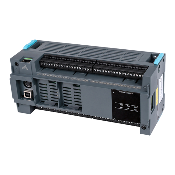
1. Appearance and Part Names
Ethernet
RS232
Expansion card 1
Expansion card 2
USB
RS485
Fig 1-1Appearance and part name of module
2. Model Description
X
MU 2 00 - 32 32 B T A
Fig 2-1 Model description
3. Installation Description
3.1 Environmental Temperature
Status Indicator
Input indicator
Output indicator
Special functions (optional)
Power input mode:
A: 220Vac input
D: 24Vdc input
N: no external power input
Output mode:
R: relay output;
T: transistor output;
M: Mixed output
N: no output
Module type
B: Basic module
E: Extension module
Output points. In this example,32.
Input points. In this example,32.
Series number
MU series PLC
Temperature range for PLC usage:0℃~55℃.
should be selected when the ambient temperature exceeds 55° C for a long
time.
3.2 Installation Site
◆ Place without corrosion, flammable and explosive gas and liquid.
◆
Solid place without vibration.
◆
This controller is designed for II standard installation environment
and 2-level pollution occasions.
3.3 Installation Method
The PLC must be installed horizontally on the backplane of the
electrical cabinet, and maintain a distance of more than 20cm from the
peripheral equipment or cabinet wall. The installation in other directions is
not conducive to the PLC heat dissipation, and there can be no heating
equipment under the PLC. As shown in the picture below:
Horizontal installation
Fig 3-1 Installation position diagram
3.4 Installation Method
DIN rail mounting
Generally, you can mount the PLC onto a 35mm-wide rail (DIN). Open
the DIN snap-fit at the bottom of the module and lock the bottom of the
module onto the DIN rail;
Rotate module close to the DIN guide rail and close the DIN snap-fit
with a double-checking, as the following figure:
Fig 3-2 Diagram of installation on DIN rail
Screw fixing
Fixing the PLC with screws can stand greater shock than DIN rail
mounting. M3 or M4 screws can be chosen to fix the PLC onto the backboard
of the electric cabinet through the mounting holes on PLC enclosure, as the
following figure.
A well-ventilated place
Ceiling installation
Vertical installation
Flatwise installation
Advertisement

Related Manuals for Megmeet MU200 Series


Summary of Contents for Megmeet MU200 Series
- Page 1 55° C for a long User Manual time. Thank you for using MU200 series PLC. Before using the product, 3.2 Installation Site please carefully read this manual so as to better understand it, fully use it, and ensure safety.
-
Page 2: Indicator Definition
24Vdc power supply (24 V/0V) for input terminal or other equipment. 7. User Terminal Introduction The MU200 series terminal is a single row of 4mm pitch screw terminals. The silk screen of the terminal is shown in the following figure. - Page 3 All input channels share one input common terminal MU200 series PLC can provide a "S/S" terminal, in which user can select the signal input mode to be source type or leakage type. Connect S/S terminal to + 24 V power supply, that is the input channel is set to leakage type mode, and the NPN type sensor can be connected.
- Page 4 Fuse protection and the RUN indicator lights rapidly. However, ERR indicator lighting The output terminals of MU200 series PLC are composed of several indicates that there is an error in the user program or system. Please groups, which are electrically isolated each other, and the output contacts of troubleshoot the error according to the instructions in MU200 Series different groups are connected to different power circuits;...
- Page 5 1. The warranty range is confined to the PLC only. and input thin wires terminal status 2. Warranty period is 18 months, within which period Megmeet conducts free Poor signal circuit contact Check the cable maintenance and repairing to the PLC that has any fault or damage under connection and the normal operation conditions.
Need help?
Do you have a question about the MU200 Series and is the answer not in the manual?
Questions and answers