Advertisement
MC200-8TC
User Quick Start Manual
Thank you for using MC200 series PLC. Before using the product,
please carefully read this manual so as to better understand it, fully use it,
and ensure safety. This quick start manual is to offer you a quick guide to the
design, installation, connection and maintenance of MC200 series PLC,
convenient for on-site reference.
This manual is for the following MC200 series members:
MC200-8TC Thermocouple Module
Version:V1.2.1
Revision Date:2010-06-30
BOM Code:R33010007
For detailed product information, please refer to MC200 Series PLC
User
Manual ,
X-Builder
Programming
MC200/MC100 Series PLC Programming Reference Manual . For ordering the
above user manuals, contact your Megmeet distributor or sales office.
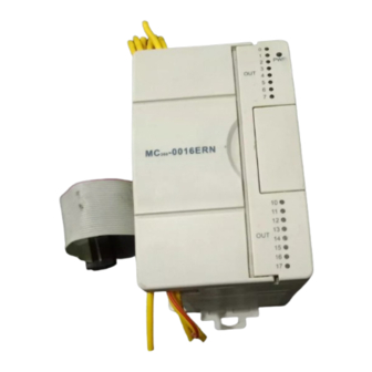
1. Appearance and Part Names
Fig. 1-1 Appearance and part name
2. Installation Description
2.1 Installation method
DIN rail mounting
Generally, you can mount the PLC onto a 35mm-wide rail (DIN). Open
the DIN snap-fit at the bottom of the module and lock the bottom of the
module onto the DIN rail; Rotate module close to the DIN guide rail and close
the DIN snap-fit with a double-checking.
Screw fixing
Fixing the PLC with screws can stand greater shock than DIN rail
mounting. M3 screws can be chosen to fix the PLC onto the backboard of the
electric cabinet through the mounting holes on PLC enclosure, as the
following figure.
Thermocouple
Module
Software
User
Manual ,
2.2 Cable connection and specification
It is recommended to use stranded copper cables and prefabricate
insulated plugs to ensure connection quality. The following table lists the
sectional areas and models of the recommended cables.
Recommended
Cable
AC power line
AWG12/AWG18
(L、N)
Ground
and
line
Input signal (X)
AWG18/AWG20
Output signal
AWG18/AWG20
(Y)
Fix the prepared cable head onto the PLC terminals with screws
correctly. Fastening torque: 0.5~0.8Nm.
◆For the safety (to prevent electric shock and fire accidents) and lower
noise, the ground terminal of the controller should be connected in
accordance with the requirements from national electrical regulations, and
the ground resistance should be less than 100 Ω . Single point grounding
should be used when wiring multiple controllers, and the ground wire cannot
form a loop. As shown in the diagram below:
×
Note for wiring:
1. Thermocouple signals are connected by shielding compensation
cables, which should be routed separate from power cables or other cables
that may be source of electrical interference. An appropriate compensation
cables( within 100m) is recommended to reduce the noise interference.
Compensation cable has impedance, which can cause measurement error.
This problem can be addressed through characteristics adjustment. For
details, refer to 3 Setting Characteristics.
Terminal and heat shrink
Cross-Section
NO.
1.0—2.0mm
2
insulated tubing terminal, or
Wire end tinning treatment
AWG12
2.0mm
2
insulated tubing terminal, or
Wire end tinning treatment
0.8—1.0mm
2
UT1-3 or OT1-3 cold-pressed
0.8—1.0mm
2
√
tubing
H1.5/14 prefabricate
H2.0/14 prefabricate
terminal, Φ3 or Φ4 heat
shrink tubing
Advertisement
Table of Contents

Related Manuals for Megmeet MC200 Series


Summary of Contents for Megmeet MC200 Series
- Page 1 Module User Quick Start Manual Thank you for using MC200 series PLC. Before using the product, please carefully read this manual so as to better understand it, fully use it, and ensure safety. This quick start manual is to offer you a quick guide to the design, installation, connection and maintenance of MC200 series PLC, convenient for on-site reference.
-
Page 2: Technical Specification
2. If there is too much electrical interference, connect the shielded Specifications Item ground FG to the grounding PG. Celsius (°C) Fahrenheit (°C) channels) 3. Grounding terminal PG of the module is well grounded. Type K -100°C~+1200°C Type K -148°F~+2192°F 4. -
Page 3: Application Example
Note: When the mode is set to 1 or 3, that is, the output is in the Positive thermocouple of Positive thermocouple of CH7 Fahrenheit (0.1℉), the corresponding unit will read a temperature with the 0.1 Negative thermocouple of Negative thermocouple of CH7 ℉... -
Page 4: Buffer Memory (Bfm)
6.2 System block configuration #205 Current value of CH6 Current value of channel 6 #206 Current value of CH7 Current value of channel 7 #207 Current value of CH8 Current value of channel 8 #300 Error status word 1 #301 Error status word 2 #400 Initialization... - Page 5 #923 CH6-A1 Default: 10000 (Input mode 0) Mode T, unit: 0.1 ℉ #924 CH7-D0 Default: 0 (Input mode 0) Mode R, unit: 0.1 ℃ #925 CH7-A0 Default: 0 (Input mode 0) Mode R, unit: 0.1 ℃ #926 CH7-D1 Default: 2000 (Input mode 0) Mode S, unit: 0.1 ℉...
-
Page 6: Routine Inspection
9. Inspection Upon Fault +2047 b12~b15: Reserved In case of abnormality, check the following items: Table 7-4 Status information of BFM#301 ● The status of the POWER indicator Channel ON (1) OFF (0) ON: the extension cable is properly connected; Decoupling in CH1 CH1 is normal OFF: check the extension cable connection and the basic module. - Page 7 Notice 1. The warranty range is confined to the PLC only. 2. Warranty period is 18 months, within which period Megmeet conducts free maintenance and repairing to the PLC that has any fault or damage under the normal operation conditions.
Need help?
Do you have a question about the MC200 Series and is the answer not in the manual?
Questions and answers