Advertisement
Quick Links
MC5000S Remote IO Communication Coupler Module
User Quick Start Manual
Thank you for using MC5000 remote IO communication coupler module.
Before using the product, please carefully read this manual so as to better
understand it, fully use it, and ensure safety. This quick start manual is to
offer you a quick guide to the design, installation, connection and
maintenance of MC5000S module for the convenience of users to access the
required information on site, and provide a brief introduction to relevant
accessories, FAQs, etc.
This manual is suitable for the following members:
MC5000S-PN
Profinet Remote IO module
Version:V1.0
Date:2023-11-3
For detailed product information, please refer to MC5100 Series PLC User
Manual , Profinet Remote IO Instruction. For ordering the above user manuals,
contact your Megmeet distributor or download from MEGMEET website
(www.megmeet.com).
1.
Appearance and parts name
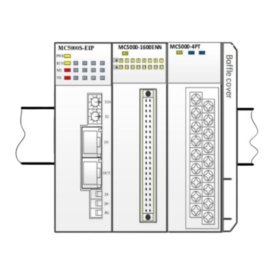
1.1 Module appearance and terminal introduction
Name
Indicator
Display the module running status
I/O port
2×RJ45
Power port
Connect to 24V power supply
Expansion port
Connect to expansion module, up to 12 modules
2.
Model Introduction
2.1 Model and technical specification
Table 2-1 Technical specification
Model
Dimensions(H×L×W)
Power supply
Description
MC5000S-EIP
110.5×115×52.5(mm)
DC24V(-15%~+20%)
Power current
Expansion module quantity
Bus protocol
Connection
3.
Installation
3.1 DIN Slot Mounting
Mounted by 35mm-width DIN slots, the expansion module connects each
other with snap-fit, which you can push it along the front direction of the
module to fasten modules tightly. Then, users can open the DIN snap-fit at
the bottom of the module and lock the bottom onto the DIN rail; Rotate
module close to the DIN guide rail and close the DIN snap-fit with a
double-checking, as the following figure:
3.2 Cable connection and specification
It is recommended to use
insulated terminal ends to ensure the quality of the wiring. The following
table lists the cross-section and models of the recommended cables.
Cross-
Cable
Cable No.
section
Power cable
0.8~1.0mm²
AWG16、18
PG cable
1.0mm²
Fix the finished cable end on the coupler terminal by the screw in a
correct position and 2lbf in tightening torque, to ensure reliable connection
without damaging the screw.
Figure 3-2 shows the recommended cable preparation method.
Fig. 1-2 Cable diagram
2A (Max.)
12
Profinet
2×RJ45
stranded copper
cables and prefabricate
Terminal and heat shrink tube
PVC insulated pin-type terminal
AWG16
1
Advertisement

Related Manuals for Megmeet MC5000S-PN


Summary of Contents for Megmeet MC5000S-PN
- Page 1 For detailed product information, please refer to MC5100 Series PLC User double-checking, as the following figure: Manual , Profinet Remote IO Instruction. For ordering the above user manuals, contact your Megmeet distributor or download from MEGMEET website (www.megmeet.com). Appearance and parts name 1.1 Module appearance and terminal introduction...
- Page 2 Topological structure: Linear, Star Table 6-1 Common expansion module list Transmission distance: Less than 100M between two Model Description Terminal points Remote IO Module MC5000S-PN Profinet coupler RJ45 Expansion IO Module Indicator definition 32-point 24VDC input/ MC5000-3232ETN Cluster terminal 32-point transistor output...
- Page 3 Profinet Remote IO Instruction Manual to correct the error. Check whether the PG of 4. Then, connect to the power supply of the coupler external system to MC5000S-PN is reliable debug. BF indicator is Check whether the output...
- Page 4 Notice 1. The warranty range is confined to the PLC only. 2. Warranty period is 18 months, within which period Megmeet conducts free maintenance and repairing to the PLC that has any fault or damage under the normal operation conditions.
Need help?
Do you have a question about the MC5000S-PN and is the answer not in the manual?
Questions and answers