
Related Manuals for VWR avantor 611-5597


Summary of Contents for VWR avantor 611-5597
- Page 1 Instruction manual Antivibrating Table Europen Catalogue Number: 611-5597 vwr.com I Instruction manual VWR ® VWR_TAVPLUS_ENG_Apr24.docx...
- Page 2 Legal Address of Manufacturer Europe VWR International bv Researchpark Haasrode 2020 Geldenaaksebaan 464 B-3001 Leuven + 32 16 385011 http://be.vwr.com UK Importer VWR International Ltd Hunter Boulevard, Magna Park Lutterworth, Leicestershire, LE17 4XN uk.vwr.com Country of origin China Intended use...
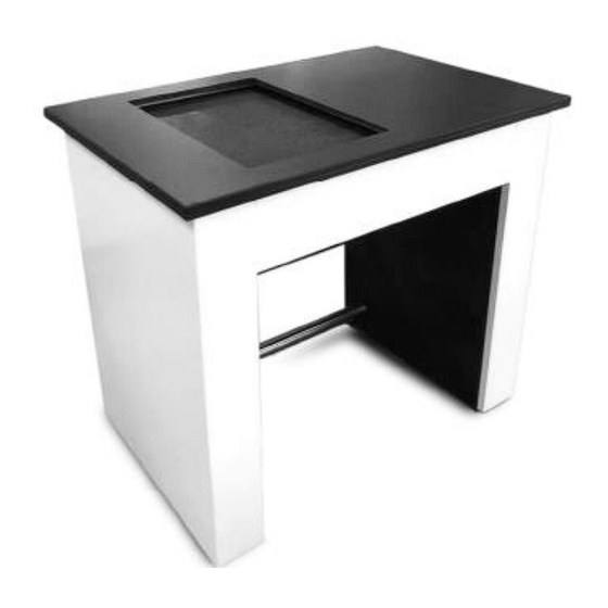
- Page 3 Assembling of the antivibrating table External structure Granite floor Spherical supports (4) Internal structure Fixing rods (3) Fig. 1 IMPORTANT NOTE: the table must be assembled by at least 2 persons to reduce chances of getting hurt. Trying to mount the table alone might be dangerous Decide before starting what the final location of the table will be in the laboratory.
- Page 4 Open the wooden packages containing the two vertical granite legs and the package containing the granite floor. Open the package containing the external metal structure and extract the three metal rods, the four rectangular plates and the tools that will be used for assembly (wrenches and screws). Place the four rectangular plates of plastic material (orange-red colour) in the position where the legs will be placed, two plates for each leg, one in the front part of the leg, the other in the back part.
- Page 5 Fig. 6 Take the four metal supports with spherical ends and screw two of them for each granite leg into the vertical holes located on the upper surface of each leg. Insert all four supports to the same depth and screw the adjustment nut (see 1 in Fig.7) until it stops (do not tighten locknut 2 for the moment) Fixing locknut Adjustment nut...
-
Page 6: Proper Use And Maintenance
Once these operations have been completed, you can fix the lock nut (2 in Fig. 7) of each support, using the specific wrench provided. Assembling of the external structrure Before assembling the external structure, check that the granite surface is well centered in the various horizontal directions. -
Page 7: Technical Service
VWR International warrants that this product will be free from defects in material and workmanship for a period of two (2) years from date of delivery. If a defect is present, VWR will, at its option and cost, repair, replace, or refund the purchase price of this product to the customer, provided it is returned during the warranty period. - Page 8 Local VWR offices in Europe and Asia Pacific Poland Austria Hungary VWR International Sp. z o.o. VWR International GmbH VWR International Kft. Limbowa 5 Graumanngasse 7 Simon László u. 4. 80-175 Gdansk 1150 Vienna 4034 Debrecen Tel.: +48 058 32 38 210 Tel.: +43 1 97 002 0...
- Page 9 I Instruction manual VWR ® VWR_TAVPLUS_ENG_Apr24.docx...
Need help?
Do you have a question about the avantor 611-5597 and is the answer not in the manual?
Questions and answers