
Related Manuals for Trox Technik EKA2-EU


Summary of Contents for Trox Technik EKA2-EU
- Page 1 Assembly and operating instructions GB/en Smoke control damper EKA2-EU in accordance with EN 12101-8 Declaration of Performance DoP / EKA2-EU / DE / 001 Read the instructions prior to performing any task!
- Page 2 TROX GmbH Heinrich-Trox-Platz 47504 Neukirchen-Vluyn Germany Phone: +49 (0) 2845 202-0 Fax: +49 (0) 2845 202-265 E-mail: trox-de@troxgroup.de Internet: http://www.troxtechnik.com Installation and operating instructions (translation of the original) CD10078, 1, GB/en 07/2024 © 2024 Smoke control damper EKA2-EU...
- Page 3 To ensure that your request is processed as quickly as possible, please keep the following information ready: Product name TROX order number Delivery date Brief description of defect or issue Online www.trox.de Phone +49 2845 202-0 Smoke control damper EKA2-EU...
- Page 4 Warning – danger zone. NOTICE! Potentially hazardous situation which, if not avoided, may result in property damage. ENVIRONMENT! Environmental pollution hazard. Tips and recommendations Useful tips and recommendations as well as informa- tion for efficient and fault-free operation. Smoke control damper EKA2-EU...
-
Page 5: Table Of Contents
5.11.2 EKA2-EU - Single-multi for dimensions ≥ W × H = 600 × 400 mm ....62 1.1 General safety instructions ......6 5.11.3 EKA2-EU - Grille-multi for dimensions ≥ 1.2 Correct use ..........6 W × H = 600 × 400 mm ....... 63 1.3 Qualified staff .......... -
Page 6: Safety
1.2 Correct use Skilled qualified electrician Skilled qualified electricians are individuals who have Smoke control dampers type EKA2-EU are used to sufficient professional or technical training, knowledge remove smoke or heat, and to supply air within smoke and actual experience to enable them to work on elec- and heat venting systems, in the event of an incident. -
Page 7: Technical Data
EN 1751 – Ventilation for buildings – Air terminal devices DoP / EKA2-EU / DE / 001 Declaration of Performance Temperatures may differ for units with attachments. Details for other applications are available on request. Specifications apply to uniform upstream velocities and outflows of the smoke control dampers. - Page 8 The last two digits of the year in which the CE Number of the European standard and year of its marking was affixed publication Year of manufacture QR code to access the documentation Manufacturer's address Product identification number Smoke control damper EKA2-EU...
-
Page 9: Eka2-Eu With Actuator
Dimensions without thermal insulation, when used with thermal insulation Ä Chapter 5.11 ‘Installation of thermal insulation’ on page 50 Weight EKA2-EU with actuator + approx. 1.1 kg (BEE...) or + 2.6 kg (BE...), see table Ä 10 . For sizes 1 and 2, see table Ä... - Page 10 Weight [kg] for casing length L = 305 [mm] / L = 500 [mm] Sizes Damper blade (30 mm thick) with lip seal for sizes 1, damper blade (40 mm thick) with travel stop seal for size 2. Smoke control damper EKA2-EU...
- Page 11 Fig. 4: Flange holes L = 500 mm – uneven and even number of holes B or H [mm] 200/200 – 355 360 – 630 635 –800 805 – 1250 1255 – 1500 No. of holes on each side * – * Excluding corner holes Smoke control damper EKA2-EU...
-
Page 12: Transport And Storage
Store the product in a dry place and away from direct sunlight. Do not expose the unit to the effects of weather (not even in its packaging). Storage temperature: -30 °C to 50 °C, non-con- densing. Packaging Properly dispose of packaging material. Smoke control damper EKA2-EU... -
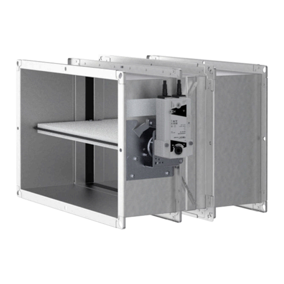
Page 13: Parts And Function
EKA2-EU (vew) as additional supply air inlet fire compartments. ⑨ Cover grille The EKA2-EU smoke control damper is made of galvan- Smoke control dampers are completely closed during ised sheet metal, and the damper blade is actuated normal operation. For smoke extraction, the smoke... - Page 14 Depending on the system layout, the damper blade can be fully opened, fully closed or in the intermediate position. Depending on where the dampers are installed, country-specific regu- lations may apply to ventilation applications. Smoke control damper EKA2-EU...
-
Page 15: Installation
Installation Overview of installation situations Installation 5.1 Overview of installation situations Fig. 7: EKA2-EU – assignment of the installation opening Single damper Multiple use of the installation opening, 2 – 3 Multiple use of the installation opening, on top of each other... -
Page 16: Safety Notes Regarding Installation
If the wall or ceiling is very thick, use an extension has hardened. piece. Test the function of the smoke control damper. Ensure that the installation of EKA2-EU does not Connect the air duct. reduce the structural safety of the supporting con- Establish the electrical connection. - Page 17 Minimum distance between two smoke control dampers. Each damper is to be installed in its own installation opening unless stated otherwise in the installation details. The distance between two smoke control dampers is then ≥ 200 mm. Smoke control damper EKA2-EU...
- Page 18 Mortar-based installation 40 – 100 – 90 If L = 500 mm, With L = 305 mm and stacked installation, the distance is 75 - 90 mm. The perimeter gap "s1" is 40 - 100 mm. Smoke control damper EKA2-EU...
- Page 19 If reveals with appropriate fire resistance are used, a mortar bed depth of 100 mm is sufficient. Fig. 11: EKA2-EU – mortar bed Fig. 10: Perimeter gap 5.10 Wall fixing tab EKA2-EU 2.1 Mortar...
- Page 20 Requirements for wall and ceiling systems Compartment walls and safety partition walls may EKA2-EU smoke control dampers may be installed in be provided with sheet steel inserts and may require wall and ceiling systems if these walls and ceilings less space between the metal frame constructions.
- Page 21 Concrete bases with a height £ 150 mm do not require reinforcement. In the case of distances to neighbouring supporting constructions, the reinforcement can be omitted on the wall side if carried out correctly, distance to load- bearing components ³ 40 mm. Smoke control damper EKA2-EU...
-
Page 22: Constructions
Installation Constructions > EKA2-EU – Single-multi 5.4 Constructions 5.4.1 EKA2-EU – Multi-multi Fig. 13: EKA2-EU – Multi-multi Information on thermal insulation, Ä 5.11 ‘Installation of thermal insulation’ on page 50 5.4.2 EKA2-EU – Single-multi Fig. 14: EKA2-EU – Single-multi Information on thermal insulation, Ä... -
Page 23: Eka2-Eu - Grille-Multi
Installation Constructions > EKA2-EU – Grille-grille 5.4.3 EKA2-EU – Grille-multi Fig. 15: EKA2-EU – Grille-multi Information on thermal insulation, Ä 5.11 ‘Installation of thermal insulation’ on page 50 5.4.4 EKA2-EU – Grille-grille Can be used for air flow into or via vestibules Fig. -
Page 24: Solid Walls
H + 200 max. 40 – 100 – 90 With length 305 mm and installation of fire dampers on top of each other, the distance between EKA2-EU fire dampers has to be at least 75 mm. Additional requirements: solid walls Solid wall, Ä... -
Page 25: Mortar-Based Installation
Fig. 19: Mortar-based installation into a solid wall, flange to flange, illustration shows side by side installation (applies also to installation of dampers on top of each other) EKA2-EU Solid wall Mortar up to EI 90 S at d ≥ 100 mm up to EI 120 S at d ≥ 135 mm Smoke control damper EKA2-EU... - Page 26 Solid walls > Mortar-based installation Additional requirements: mortar-based installation into solid walls Solid wall, Ä on page 20 Casing length L = 305 or 500 mm Distance to load-bearing structural elements ≥ 40 mm Smoke control damper EKA2-EU...
-
Page 27: Mortar-Based Installation - 4 Dampers With A Common Air Duct
Mortar 8.26 Sheet metal cover, t = 1 mm (by others) Solid wall 8.27 Seal, full-surface, Kerafix or equivalent Sheet steel screw or rivet, at a distance of Up to EI 120 S ~ 150 mm Smoke control damper EKA2-EU... - Page 28 Inspection accesses and the product sticker must remain accessible. Distance to load-bearing structural elements ≥ 40 mm Smoke control damper EKA2-EU...
-
Page 29: Lightweight Partition Walls With Cladding On 2 Sides
– 90 Trim panels are optional or according to installation details With length 305 mm and installation of fire dampers on top of each other, the distance between EKA2-EU fire dampers has to be at least 75 mm. Smoke control damper EKA2-EU... - Page 30 Lightweight partition walls with cladding on 2 s... > General information Lightweight partition wall with metal frame construction and cladding on both sides Fig. 22: Lightweight partition wall with metal frame construction and cladding on both sides; for picture caption, see Fig. 23 Smoke control damper EKA2-EU...
- Page 31 / safety partition wall, installation near the Closed side of metal section must face the ceiling installation opening Solid ceiling/solid floor Arrangement may vary Dry wall screw Screw or steel rivet Mineral wool, depending on wall construction UW section Smoke control damper EKA2-EU...
- Page 32 Fig. 24: Metal frame construction for a compartment wall, single stud system and double stud system Dry wall screw UW section Hexagon head screw M6 CW section Carriage bolt, L ≤ 50 mm, with washer and nut UA section Steel rivet Installation opening according to installation 5.14 Angle bracket details Smoke control damper EKA2-EU...
- Page 33 The structural safety of the wall must be ensured (by others). Compensation measures, especially with regard to large installation openings (such as for multiple installation), must be determined on a case to case basis (by others). Smoke control damper EKA2-EU...
-
Page 34: Mortar-Based Installation
Lightweight partition wall with metal frame con- Solid ceiling/solid floor struction, cladding on both sides up to EI 90 S at d ≥ 100 mm up to EI 120 S at d ≥ 135 mm Smoke control damper EKA2-EU... - Page 35 Additional requirements: mortar-based installation into lightweight partition walls and compartment walls Lightweight partition wall, Ä on page 20 Casing lengths L = 305 and 500 mm Distance to load-bearing structural elements ≥ 40 mm Smoke control damper EKA2-EU...
-
Page 36: Shaft Walls With Metal Support Structure - Asymmetrical
H + 200 max. 40 – 100 – 90 With length 305 mm and installation of fire dampers on top of each other, the distance between EKA2-EU fire dampers has to be at least 75 mm. Smoke control damper EKA2-EU... - Page 37 The structural safety of the wall must be ensured (by others). Compensation measures, especially with regard to large installation openings (e.g. for mul- tiple installation), must be determined on a case to case basis (by others). Smoke control damper EKA2-EU...
-
Page 38: Mortar-Based Installation
Shaft walls with metal support structure - asymm... > Mortar-based installation 5.7.2 Mortar-based installation Mortar-based installation in asymmetrical shaft walls Fig. 28: Mortar-based installation in asymmetrical shaft walls EKA2-EU (actuator on the outside of the shaft) Construction Ä 5.11 ‘Installation of thermal Mortar insulation’... -
Page 39: Solid Ceiling Slabs
H + 200 max. 40 – 100 – 90 With length 305 mm and installation of fire dampers on top of each other, the distance between EKA2-EU fire dampers has to be at least 75 mm. Smoke control damper EKA2-EU... - Page 40 (by others). Compen- sation measures, especially with regard to large installation openings (such as for multiple installa- tion), must be determined on a case to case basis (by others). Smoke control damper EKA2-EU...
-
Page 41: Mortar-Based Installation Into Solid Ceiling Slabs
Mortar-based installation into a solid ceiling slab, flange to flange Fig. 32: Mortar-based installation into a solid ceiling slab, flange to flange, illustration shows upright installation (applies also to suspended installation) EKA2-EU Solid ceiling slab Mortar Up to EI 120 S Smoke control damper EKA2-EU... - Page 42 Fig. 33: Mortar-based installation into a solid ceiling slab with screed and footfall sound insulation, suspended or upright EKA2-EU 6.22 Screed Mortar 6.23 Footstep sound insulation Concrete Up to EI 120 S Solid ceiling slab Smoke control damper EKA2-EU...
- Page 43 Solid ceiling slab Additional requirements: mortar-based installation into solid ceiling slabs Solid ceiling slab, Ä on page 21 Casing length L = 305 or 500 mm Distance to load-bearing structural elements ≥ 40 mm Smoke control damper EKA2-EU...
-
Page 44: Mortar-Based Installation Into A Concrete Base
Solid ceiling slab table Air duct/extension piece Up to EI 120 S Note: EI 120 S also for two EKA2-EU at a distance of ³ 220 mm. Minimum number of fixing points in the ceiling slab H [mm] B [mm] ≥... - Page 45 Concrete bases with H ≤ 150 mm do not require reinforcement Distance between two EKA2-EU ≥ 220 mm Distance to load-bearing structural elements ≥ 40 mm Note:...
-
Page 46: Solid Wood Ceilings
(by customer). Compensation measures, especially with regard to large installation openings (such as for multiple installation), must be determined on a case-to-case basis (by customer). Smoke control damper EKA2-EU... -
Page 47: Mortar-Based Installation Into Solid Wood Ceilings
Note: Structural and fire resistance properties of the ceiling construction, including the attachment to the con- crete or any required reinforcement, have to be eval- uated and ensured by others. Smoke control damper EKA2-EU... -
Page 48: Wooden Beam Ceilings
(by customer). Compensation measures, especially with regard to large installation openings (such as for multiple installation), must be determined on a case-to-case basis (by customer). Smoke control damper EKA2-EU... -
Page 49: Mortar-Based Installation Into Wooden Beam Ceilings
Note: Structural and fire resistance properties of the ceiling construction, including the attachment to the con- crete or any required reinforcement, have to be eval- uated and ensured by others. Smoke control damper EKA2-EU... -
Page 50: Installation Of Thermal Insulation
Installation Installation of thermal insulation > EKA2-EU - Multi-multi for dimensions ≥ W × H =... 5.11 Installation of thermal insulation 5.11.1 EKA2-EU - Multi-multi for dimensions ≥ W × H = 600 × 400 mm Overview using the example of Multi-multi * Fig. - Page 51 Installation Installation of thermal insulation > EKA2-EU - Multi-multi for dimensions ≥ W × H =... Step 1 Fig. 41: EKA2-EU – Multi-multi EKA2-EU with actuator BEE... or BE... For the rest of the legend, see Fig. 42 Smoke control damper EKA2-EU...
- Page 52 Installation Installation of thermal insulation > EKA2-EU - Multi-multi for dimensions ≥ W × H =... Fig. 42: EKA2-EU – Multi-multi EKA2-EU see table 5.28 Welding pin Depending on height 6.45 DuctRock Slab or Conlit Fireboard, 90 mm With connection of a multi-steel cable on the oper-...
- Page 53 Installation Installation of thermal insulation > EKA2-EU - Multi-multi for dimensions ≥ W × H =... Step 2 Fig. 43: EKA2-EU – Multi-multi EKA2-EU with actuator BEE... or BE... For the rest of the legend, see Fig. 44 Smoke control damper EKA2-EU...
- Page 54 Installation Installation of thermal insulation > EKA2-EU - Multi-multi for dimensions ≥ W × H =... Fig. 44: EKA2-EU – Multi-multi EKA2-EU Depending on height 6.45 DuctRock Slab or Conlit Fireboard, 90 mm Depending on height 6.47 Angle section, DuctRock Slab or Conlit Fire- 290 mm with actuator BEE...
- Page 55 Installation Installation of thermal insulation > EKA2-EU - Multi-multi for dimensions ≥ W × H =... Step 3 Fig. 45: EKA2-EU – Multi-multi EKA2-EU with actuator BEE... or BE... For the rest of the legend, see Fig. 46 Smoke control damper EKA2-EU...
- Page 56 Installation Installation of thermal insulation > EKA2-EU - Multi-multi for dimensions ≥ W × H =... Fig. 46: EKA2-EU – Multi-multi EKA2-EU see table 6.45 DuctRock Slab or Conlit Fireboard, 90 mm Depending on height 6.46 Conlit Fireboard, 60 mm...
- Page 57 Installation Installation of thermal insulation > EKA2-EU - Multi-multi for dimensions ≥ W × H =... Step 4 Construction of drive cover Fig. 47: EKA2-EU – Multi-multi EKA2-EU with actuator BEE... or BE... For the rest of the legend, see Fig. 48...
- Page 58 Installation Installation of thermal insulation > EKA2-EU - Multi-multi for dimensions ≥ W × H =... Fig. 48: EKA2-EU – Multi-multi EKA2-EU 10.26 Name plate 6.45 DuctRock Slab or Conlit Fireboard, 90 mm see table 6.46 Conlit Fireboard, 60 mm see table 8.48...
- Page 59 Installation Installation of thermal insulation > EKA2-EU - Multi-multi for dimensions ≥ W × H =... Step 5 Fig. 49: EKA2-EU – Multi-multi EKA2-EU 6.45 DuctRock Slab or Conlit Fireboard, 90 mm 5.28 Welding pin Air duct/extension piece Spacing of the welding pins (5.28) ≤ 150 mm.
- Page 60 Installation Installation of thermal insulation > EKA2-EU - Multi-multi for dimensions ≥ W × H =... Step 6 Fig. 50: EKA2-EU – Multi-multi EKA2-EU 6.47 Angle section 40 x 40 mm 6.45 DuctRock Slab or Conlit Fireboard, 90 mm Air duct/extension piece Screw the transom (6.47) to the wall or ceiling all round at a distance of 20 mm around the thermal insulation (6.45),...
- Page 61 Installation Installation of thermal insulation > EKA2-EU - Multi-multi for dimensions ≥ W × H =... Step 7 Fig. 51: EKA2-EU – Multi-multi EKA2-EU 6.46 Conlit Fireboard, 60 mm Air duct/extension piece Smoke control damper EKA2-EU...
-
Page 62: Eka2-Eu - Single-Multi For Dimensions ≥ W × H = 600 × 400 Mm
Installation Installation of thermal insulation > EKA2-EU - Single-multi for dimensions ≥ W × H ... 5.11.2 EKA2-EU - Single-multi for dimensions ≥ W × H = 600 × 400 mm Overview using the example of Single-Multi * Fig. 52: EKA2-EU – Single-multi EKA2-EU with actuator BEE... -
Page 63: Eka2-Eu - Grille-Multi For Dimensions ≥ W × H = 600 × 400 Mm
Installation Installation of thermal insulation > EKA2-EU - Grille-multi for dimensions ≥ W × H ... 5.11.3 EKA2-EU - Grille-multi for dimensions ≥ W × H = 600 × 400 mm Overview using the example of Grille-multi * Fig. 53: EKA2-EU – Grille-multi EKA2-EU with actuator BEE... -
Page 64: Eka2-Eu - Multi-Multi For Dimensions < W × H = 600 × 400 Mm (For Example, W × H = 600 × 400 Mm)
Installation Installation of thermal insulation > EKA2-EU - Multi-multi for dimensions < W × H =... 5.11.4 EKA2-EU - Multi-multi for dimensions < W × H = 600 × 400 mm (for example, W × H = 600 × 400 mm) Overview using the example of Multi-multi * Fig. - Page 65 Installation Installation of thermal insulation > EKA2-EU - Multi-multi for dimensions < W × H =... Step 1 Fig. 55: EKA2-EU – Multi-multi EKA2-EU with actuator BEE... For the rest of the legend, see Fig. 56 Smoke control damper EKA2-EU...
- Page 66 Installation Installation of thermal insulation > EKA2-EU - Multi-multi for dimensions < W × H =... Fig. 56: EKA2-EU – Multi-multi EKA2-EU see table 6.45 DuctRock Slab or Conlit Fireboard, 90 mm With connection of a multi-steel cable on the oper-...
- Page 67 Installation Installation of thermal insulation > EKA2-EU - Multi-multi for dimensions < W × H =... Step 2 Fig. 57: EKA2-EU – Multi-multi EKA2-EU with actuator BEE... For the rest of the legend, see Fig. 58 Smoke control damper EKA2-EU...
- Page 68 Installation Installation of thermal insulation > EKA2-EU - Multi-multi for dimensions < W × H =... Fig. 58: EKA2-EU – Multi-multi EKA2-EU see table 6.45 DuctRock Slab or Conlit Fireboard, 90 mm Depending on height 6.46 Conlit Fireboard, 60 mm...
- Page 69 Installation Installation of thermal insulation > EKA2-EU - Multi-multi for dimensions < W × H =... Step 3 Construction of drive cover Fig. 59: EKA2-EU – Multi-multi EKA2-EU with actuator BEE... For the rest of the legend, see Fig. 60...
- Page 70 Installation Installation of thermal insulation > EKA2-EU - Multi-multi for dimensions < W × H =... Fig. 60: EKA2-EU – Multi-multi EKA2-EU 10.26 Name plate 6.45 DuctRock Slab or Conlit Fireboard, 90 mm see table 6.46 Conlit Fireboard, 60 mm see table 8.48...
- Page 71 Installation Installation of thermal insulation > EKA2-EU - Multi-multi for dimensions < W × H =... Step 4 Fig. 61: EKA2-EU – Multi-multi EKA2-EU 6.45 DuctRock Slab or Conlit Fireboard, 90 mm 5.28 Welding pin Air duct/extension piece For information on the distances between the welding pins (5.28), see Fig. 49...
- Page 72 Installation Installation of thermal insulation > EKA2-EU - Multi-multi for dimensions < W × H =... Step 5 Fig. 62: EKA2-EU – Multi-multi EKA2-EU 6.46 Conlit Fireboard, 60 mm 6.45 DuctRock Slab or Conlit Fireboard, 90 mm Air duct/extension piece...
-
Page 73: Eka2-Eu - Single-Multi For Dimensions < W × H = 600 × 400 Mm (For Example, W × H = 600 × 400 Mm)
Installation Installation of thermal insulation > EKA2-EU - Single-multi for dimensions < W × H ... 5.11.5 EKA2-EU - Single-multi for dimensions < W × H = 600 × 400 mm (for example, W × H = 600 × 400 mm) Overview using the example of Single-Multi * Fig. -
Page 74: Eka2-Eu - Grille-Multi For Dimensions < W × H = 600 × 400 Mm (For Example, W × H = 600 × 400 Mm)
Installation Installation of thermal insulation > EKA2-EU - Grille-multi for dimensions < W × H ... 5.11.6 EKA2-EU - Grille-multi for dimensions < W × H = 600 × 400 mm (for example, W × H = 600 × 400 mm) Overview using the example of Grille-multi * Fig. -
Page 75: Accessories
"A" is selected, the V-piece is automatically added for these heights. See the table for the required lengths. Fig. 65: Smoke control damper with extension piece EKA2-EU 9.2 Extension piece/duct Arrangement of extension pieces Ä Table on page 76 Smoke control damper EKA2-EU... - Page 76 ** Two extension pieces required Note The movement of the damper blade must not be obstructed by any accessory. The minimum distance between the tip of the open damper blade and any accessory must be at least 50 mm. Smoke control damper EKA2-EU...
-
Page 77: Cover Grille (A-Grille)
Cover grille (A-grille) as a termination of a smoke control damper without duct connection. Fig. 67: Smoke control damper with cover grille (A-grille) EKA2-EU Air duct 9.10 End grille (A-grille), galvanised steel, mesh size 10 mm Free cross-section A [m²] Smoke control damper EKA2-EU... -
Page 78: Cover Grille (Q-Grille)
Fig. 68: Smoke control damper with cover grille (Q-grille) EKA2-EU Air duct 9.16 Cover grille (Q-grille), galvanised steel, perforated sheet 6 mm Free area A 100% of the geometric free cross-section of the EKA2-EU (B ' H) Smoke control damper EKA2-EU... -
Page 79: Smoke Extract Duct
This guarantees that maintenance work can be carried out safely and effectively and that the smoke extract system complies with the applicable regulations and standards. Smoke control damper EKA2-EU... -
Page 80: Connection To A Sheet Steel Smoke Extract Duct
Connection to a sheet steel smoke extract duct 7.2 Connection to a sheet steel smoke extract duct Fig. 69: EKA2-EU – thermal insulation design EKA2-EU 6.48 Adhesive Conlit Fix Cold, Conlit Fix, Firepro Glue 5.28* Welding pin 8.41... -
Page 81: Connection To Independent Smoke Extract Duct
Connection to independent smoke extract duct 7.3 Connection to independent smoke extract duct Fig. 70: Connection of EKA2-EU – connection frame – calcium silicate smoke extract duct EKA2-EU 8.41 Kerafix sealing strips, t = 2 mm (all-round 2.15... - Page 82 Connection to independent smoke extract duct Fig. 71: EKA2-EU – thermal insulation design EKA2-EU 6.48 Adhesive Conlit Fix Cold, Conlit Fix, Firepro Glue 5.3h* Spanplattenschraube 5 × 130 mm With large 8.40 Calcium silicate smoke extract duct washer 8.46...
-
Page 83: Electrical Connection
Actuators with 24 V AC/DC Safety transformers must be used for actuators. The connecting cables are fitted with plugs. This ensures quick and easy connection to the TROX AS-i bus system. For connection to the terminals, shorten the connecting cable. Smoke control damper EKA2-EU... -
Page 84: Actuators
8.3 Actuators Torque The actuators of the EKA2-EU are selected depending on the size, the torque and the order option (order code detail). The following tables can be used to select the corresponding actuator. Select the next larger dimension for intermediate sizes. -
Page 85: B24
IEC protection class IP 54 Protection level -30 to 55 °C Operating temperature Actuator 1 m, 3 × 0.75 mm², halogen-free Connecting cable Limit switch 1 m, 6 × 0.75 mm², halogen-free 2014/30/EU, 2014/35/EU CE conformity according to Smoke control damper EKA2-EU... -
Page 86: B230
Protection level -30 to 55 °C -30 to 50 °C Operating temperature Actuator 1 m, 3 × 0.75 mm², halogen-free Connecting cable Limit switch 1 m, 6 × 0.75 mm², halogen-free 2014/30/EU, 2014/35/EU CE conformity according to Smoke control damper EKA2-EU... -
Page 87: Actuator With Control Module
Communication modules can be connected directly to the actuator inside the encasing and establish communication and power supply to the control system. Smoke control damper EKA2-EU... -
Page 88: Troxnetcom B24A, B24Am, B24As
-5 to 75 °C -5 to 75 °C -20 to 75 °C Protection level, IEC pro- IP 42 IP 42 IP 54 tection class AS-i profile S7.A.E S7.A.E S-7.B.E (Safety at Work) and S7.A.E (motor module) Smoke control damper EKA2-EU... -
Page 89: B24Bkne
2-wire cable Screw terminals for wire 2 × 1.5 mm² Recommended cable JE-H (St) Bd FE180/E30-E90 IEC protection class II (protective insulation) Ambient temperature (normal operation) -30 – +50 C Storage temperature -40 – +80 C Smoke control damper EKA2-EU... -
Page 90: B24D And B230D
Single-wire: 0.08 – 2.5 mm² Maximum ter- Fine wire (without ferrule): 0.08 – 2.5 mm² Terminals for minal cross-sec- damper input Fine wire (ferrule with collar): 0.25 – 1.5 mm² tion Fine wire (ferrule without collar): 0.25 – 2.5 mm² Smoke control damper EKA2-EU... - Page 91 Fine wire (ferrule with collar): 0.25 – 0.75 mm² output Fine wire (ferrule without collar): 0.25 – 1.5 mm² Ambient temper- 0 – 45 °C Ambient condi- ature tions Ambient humidity 0 – 90 % Smoke control damper EKA2-EU...
-
Page 92: Commissioning/Functional Test
Smoke control dampers must be checked regularly. A functional test involves closing the smoke control damper and opening it again. This is typically done with an input signal from a central system, e.g. from the cen- tral fire alarm system. Smoke control damper EKA2-EU... -
Page 93: Maintenance
Maintenance The smoke control damper and the actuator are main- tenance-free with regard to wear but smoke control dampers must still be included in the regular cleaning of the smoke extract system. Smoke control damper EKA2-EU... - Page 94 C = As required, depending on the degree of contamination Maintenance work Item to be checked Required condition – Remedial action if necessary Smoke control damper EKA2-EU...
-
Page 95: Decommissioning, Removal And Disposal
Incorrect disposal can harm the environment. Have electronic waste and electronic components disposed of by an approved specialist disposal com- pany. Note: The smoke control damper must be dismantled into its individual components for disposal. Smoke control damper EKA2-EU... -
Page 96: Nomenclature
Installation kit E1 / E2 / E3 / EW 3.13 Metal support structure with additional leaf Installation kit ES 3.14 Solid wall made from gypsum wallboard 2.10 Installation kit GM 2.11 Installation kit TQ / TQ2 Smoke control damper EKA2-EU... - Page 97 Carriage bolt L ≤ 50 mm with washer and nut Mineral wool ≥ 1000 °C, ≥ 40 kg/m³ Mineral wool ≥ 1000 °C, ≥ 80 kg/m³ Screw or rivet, galvanised steel Mineral wool ≥ 1000 °C, ≥ 100 kg/m³ (see respective installation detail) Smoke control damper EKA2-EU...
- Page 98 Z brackets both sides, 90 × 140 × 1.5 mm Perimeter metal section 6.28 Ceiling filling (layers of boards or beams) Timber stud, at least 60 × 80 mm 6.29* Mineral wool Steel girder PAROC Hvac Fire Mat BlackCoat Timber structure (≥ 80 kg/m3) Smoke control damper EKA2-EU...
- Page 99 GTEC "J" Track 8.29 PROMATECT®-H strips d = 25 mm 7.36 GTEC "E" Stud 8.30 PROMATECT® AD, d = 40 mm 7.37 GTEC "CH" Stud 8.31 PROMATECT® L500, d = 50 mm 7.38 GTEC "CH" Stud Smoke control damper EKA2-EU...
- Page 100 72 °C / 95 °C also the specifications of the panel manufac- 10.15 Fusible link holder turer (Promat). 10.16 Fusible link holder lever Suspension system 10.17 Screw Repair damper blade 10.18 Fusible link Damper blade 10.19 Cover Rivet axis Smoke control damper EKA2-EU...
- Page 101 11.3 Pipe 11.4 Underlay material, non-combustible, to be provided by others 11.5 Underlay (by others) 11.6 Cable penetration 11.7 Potentional equalisation * Please check in advance whether the PAROC material is available in your market region. Smoke control damper EKA2-EU...
-
Page 102: Index
Lightweight partition walls with metal frame con- Weights............... struction..............20 Wiring................ 83 Lightweight partition walls with metal frame con- Wooden beam ceilings...... 15 , 21 , 48 , 49 struction and cladding on both sides......29 Smoke control damper EKA2-EU... - Page 103 TROX GmbH Phone: +49 (0) 2845 202-0 Heinrich-Trox-Platz +49 (0) 2845 202-265 47504 Neukirchen-Vluyn E-mail: trox-de@troxgroup.de Germany http://www.troxtechnik.com © 2024...
Need help?
Do you have a question about the EKA2-EU and is the answer not in the manual?
Questions and answers