Table of Contents
Advertisement
Quick Links
Advertisement
Table of Contents

Related Manuals for Monument Grills Mesa 400M


Summary of Contents for Monument Grills Mesa 400M
- Page 1 This Owner's Manual is provided and hosted by Appliance Factory Parts. Monument Grills Mesa 400M Owner's Manual Shop genuine replacement parts for Monument Grills Mesa 400M Find Your Monument Grills Grill Parts - Select From 25 Models -------- Manual continues below --------...
- Page 2 For parts ordering, call: intended for outdoor use only and is not 1- 800-530-9133 intended to be installed in or on recreational vehicles or boats. MFG No.: Mesa 400m UPC No.: 856597007744 Note to Installer Please make sure the cylinder valve Leave this Owner’s Manual with the customer...
-
Page 3: Table Of Contents
LP gas grill models are designed for use with a Monument Grills is not an original purchase and will not qualify for a warranty standard 20 lb. Liquid Propane Gas tank, not included with grill. -
Page 4: Safety Precautions
Safety Precautions A tank of approximately 12 inches in diameter by 18- 1/2 inches high is the maximum size LP gas tank to use. You must use an OPD gas tank which offers • Have your LP gas tank filled by a reputable propane gas dealer and visually inspected and an Overfill Prevention Device. - Page 5 WARNING Burner Flame Check A strong gas smell, or the hissing sound of gas indicates a serious problem with your gas grill or the LP gas tank. Failure to immediately follow the steps listed below could result in a fire or explosion that could cause serious bodily injury, death, or property damage.
- Page 6 Contents for Hardware Pack The following table illustrates a breakdown of the hardware pack. It highlights what components are used the various stages of assembly. Tools required for assembly Philips Head Screwdriver (not included). Note: The left and right sides of the grill are on your left and right as you face the front of the grill. Philips Head Screwdriver...
-
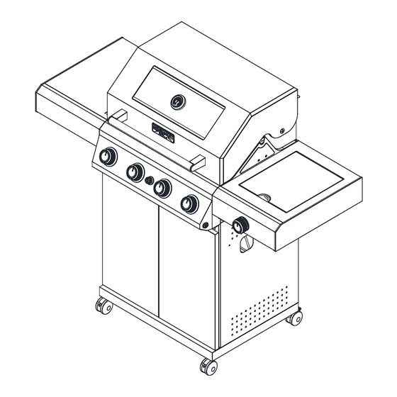
Page 7: Parts Diagram
Model Mesa 400m Parts Diagram... - Page 8 Model Mesa 400m Parts List seq. appellation qty Material code seq. appellation qty Material code Main Lid Spindle Below Door Panel D30X005561 37 A02120025 Temperature Gauge Spacing Screw Below Door Panel A0212824 A02120079 Temperature Gauge Seat Cart Bottom Panel Front Cummerbund Strip...
-
Page 9: Assembly Instructions
Assembly Instructions Insert Part No.42 into the bottom plate. Figure 1 Half screw out the screws in the bottom plate, then put Part No.30 and Part No.35 onto the relevant screw holes and screw tightly. Figure 2... - Page 10 Install Part No.33 onto the relevant place with four A screws. Figure 3 Half screw out the screws in the bottom and side plates, then put Part No.40 onto the relevant screw holes and screw tightly. Figure 4...
- Page 11 Install Part No.32 onto the relevant place with four F screws shown in Figure 5. Attention: magnet downward. Figure 5 Install Part No.2 & 3 onto the relevant place Figure 6...
- Page 12 Screw the grill body and the cart tightly with four A screws Figure 7 Install Part No.27 onto Part No.68 with one A screw. Half screw out the screw in the grill body, then put Part No.68 onto the relevant screw holes and screw tightly. Figure 8...
- Page 13 Install Part No.68 and Part No.50 with one F screw. Figure 9 Install Part No.68 onto grill body with A screw and D spacer Figure 10...
- Page 14 Half screw out the two big screws outside the grill body, then put Part No.25 onto the relevant screw holes and screw tightly. Figure 11 Install Part No.25 and Part No.50 with one F screw. Figure 12...
- Page 15 Screw part No.25 tightly with A screw and D spacer inside the grill body. Figure 13 1. Insert Part No.48, Part No.29 and Part No.56 as the figure shows. 2. Insert the wire as the figure shows. Figure 14...
- Page 16 Half screw out the screw in Part No.58, then put it into the hole of Part No.22 and screw tightly. Figure 15 cut of two white plastic tie Fixed Part No.53 onto the right plate with one F crew. Figure 16...
- Page 17 Put the C part into the relevant hole in the bottom plate. Figure 17 1. Put Part No.45 into the C part. 2. Then put the door into by pressing the flexible axis upward. Figure 18...
- Page 18 1. Install Part No.14 onto Part No.16 with two F screws. 2. Put Part No.15 into Part No.14. 3. Put the grease tray into the grill body Figure 19 1.Connect Part No.36 to Part No.47. 2.Paste the battery box onto the side panel Figure 20...
- Page 19 Put Part No. 7, Part No. 8 and Part No. 9 into the relevant place. Figure 21 Install Part No. 43 onto the bottom plate. Figure 22...
- Page 20 Connecting LP Gas Tank to LP Grill 1. Place foot ring of 20 lb tank into the hole in bottom panel. Make sure the tank valve is in OFF Regulator Connection position.(Fig.22). 2. Check the tank valve to ensure it has proper external mating threads to fit the hose and regulator assembly provided.
-
Page 21: Lighting Instructions
Checking for LP gas leaks Never test for leaks with a flame. Prior to first use, at the beginning of each season, or every time your LP gas tank is changed, you must check for gas leaks. 1. Make a 50/50 (soap/water) mild soap solution. 2. - Page 22 If Grill Still Fails To Light WARNING 1. Check gas supply and connections for leaks. Check Never lean over the grill cooking area while that all wire connections are secure. lighting your gas grill. Keep your face and body a safe distance (at least 18 inches) from the 2.
-
Page 23: Cleaning And Maintenance
Cleaning and Maintenance Cleaning Exterior Stainless Steel Surfaces To ensure a proper working unit the following proper care and maintenance is suggested. •Weathering and extreme heat can cause exterior stainless steel surfaces to turn tan in color. Machine Cleaning Cooking Grids oils used in manufacturing process of stainless steel We suggest you wash your cooking grids in a mild soap can also cause this tanning color. -
Page 24: Troubleshooting
3. Inspect each burner for damage (cracks or holes) Regardless of which burner cleaning procedure you and if such damage is found, order and install a new use, we recommend you also complete the following burner. After installation check to ensure that gas steps to help prolong burner life. -
Page 25: Cooking Instruction
Cooking Instructions Indirect Cooking WARNING Do not leave the grill unattended. To cook indirectly, the food should be placed on Your grill will get very hot. Never lean over the left or right side of your grill with the burner lit the cooking area while using your grill. - Page 26 Grill Cooking Chart...
Need help?
Do you have a question about the Mesa 400M and is the answer not in the manual?
Questions and answers