
Related Manuals for ASROCK Rack 2U2E-F Series


Summary of Contents for ASROCK Rack 2U2E-F Series
- Page 1 2U2E-F Series User Manual Version 1.0 Published August 2022 Copyright©2022 ASRock Rack INC. All rights reserved.
- Page 2 In no event shall ASRock Rack, its directors, officers, employees, or agents be liable for any indirect, special, incidental, or consequential damages (including damages for loss of profits, loss of business, loss of data, interruption of business and the like), even if ASRock Rack has been advised of the possibility of such damages arising from any defect or error in the documentation or product.
- Page 3 Setting up the Server in a Restricted Access Location • Access can only be gained by service persons or by users who have been instructed about the reasons for the restrictions applied to the location and about any precautions that shall be taken. • Access is through the use of a tool or lock and key, or other means of security, and is controlled by the authority responsible for the location.
-
Page 4: Table Of Contents
Contents Chapter 1 Introduction Shipping Box Contents Specifications Chapter 2 Server System Overview System Components Internal Features System Front Panel System Rear Panel Drive Tray LEDs Chapter 3 Hardware Installation and Maintenance Server Top Cover Power Supply System Fan Add-on Card (Riser Card) OCP NIC 3.0 Card Appendix A Installing the CPU (Intel LGA 4189 Socket) -
Page 5: Chapter 1 Introduction
In case any modifications of this documentation occur, the updated version will be available on ASRock Rack’s website without further notice. If you require technical support related to this product, please visit our website for specific information about the model you are using. -
Page 6: Shipping Box Contents
1.1 Shipping Box Contents Quantity Item /ICX2 /ROME2 2U2E-F Series Barebone (2U form factor) Power Supply Unit System Fan System Board (MB) Backplane Board (BPB) (1U2G_U2BP_G4/CB) Riser Card (2U2S_RB24_G4) Accessory Box Slide Rail If any items are missing or appear damaged, contact your authorized dealer. -
Page 7: Specifications
2U2E-F Series 1.2 Specifications 2U2E-F Series System Physical Status Form Factor 2U Rackmount Dimension 600 * 438 * 87mm (D x W x H) Support MB Size L shape 19 x 17 inch Propietary MB Model ROME2D32LM3 / SP2C621D32LM3 Front Panel... -
Page 8: Chapter 2 Server System Overview
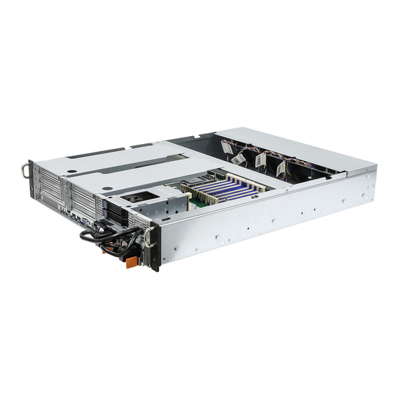
Chapter 2 Server System Overview This chapter provides diagrams showing the location of important components of the server system. 2.1 System Components 2 x AC Power Sources 4 x System Fans Riser Card (2U2S_RB24_G4) 2 x 2.5” HDD/SSD Trays Internal Power Cable Routing Hole Server Board Riser Card (2U2S_RB24_G4) -
Page 9: Internal Features
2U2E-F Series 2.2 Internal Features From 2 x 2.5” HDD/SSD Tray (Upper: HDD1 / Lower: HDD2) HDD Backplane Board Power Supply Unit (PSU2) Power Supply Unit (PSU1) Riser Card (2U2S_RB24_G4) Riser Card (2U2S_RB24_G4) OCP NIC 3.0 Slot Riser Card Mounting Bar... -
Page 10: System Front Panel
2.3 System Front Panel Description 2 x AC Power Sources 4 x System Fans 2.4 System Rear Panel HDD1 HDD2 Redundant PSU 1+1: Only one PSU is allowed to be removed while the server is running. Description 1 x OCP NIC 3.0 Slot (supports up to NVMe Gen4 device) Add-on Card Slots (support up to NVMe Gen4 devices) I/O Shield (depends on the specification of the server board) Add-on Card Slots (support up to NVMe Gen4 devices) -
Page 11: Drive Tray Leds
2U2E-F Series 2.5 Drive Tray LEDs No. Item Color Description HDD Locator LED Blue Use the locator LED to identify specific storage devices, so that you can locate them among other devices. HDD Status LED Red & Green The status LED is used to show the current status of the HDD. -
Page 12: Chapter 3 Hardware Installation And Maintenance
Chapter 3 Hardware Installation and Maintenance This chapter helps you assemble the chassis and install components. Before You Begin Before you work with the server, pay close attention to the “Important Safety Instructions” at the beginning of this manual. 1. Make sure the server is powered off. Power down the server if it is still running. -
Page 13: Server Top Cover
2U2E-F Series 3.1 Server Top Cover Removing the Server Top Cover 1. Before removing the top cover, power off the server and unplug the power cord. 2. The system must be operated with the chassis top cover installed to ensure proper cooling. - Page 14 Installing the Server Top Cover 1. Lower the top cover on the chassis, making sure the side latches align with the cutouts. Slide the top cover toward the rear side 2. Secure the top cover with the screw.
-
Page 15: Power Supply
2U2E-F Series 3.2 Power Supply The system can accommodate two AC-DC power supplies in the bay at the rear of the chassis. One power supply is required for full load operation, with the other power supply purely as a redundant, load-sharing backup. It can be removed without affecting system operation. - Page 16 Installing the Power Supply Unit To install a new power supply, please follow the steps below. 1. Carefully slide the PSU all the way into the power supply bay. 2. Make sure the power supply clicks into place and is well installed.
-
Page 17: System Fan
2U2E-F Series 3.3 System Fan The system supports hot-swappable system fans. Replacing the System Fan Please locate the failed fan by checking the fan failed LED indicator on the fan. 1. Hand release the thumbscrew on the failed fan. 2. Open the fan vent cover. - Page 18 5. Press the fan connector toward the left side so as to disengage it from the locked position. 6. Push to remove the connector from the bracket. 7. Release the screws on the fan cage. 8. Remove the system fan. 9.
-
Page 19: Add-On Card (Riser Card)
2U2E-F Series 3.4 Add-on Card (Riser Card) 1. You can install an add-on card to the chassis only when you have a riser card installed on the server board. 2. Before installing the add-on card, power off the server and unplug the power cord. - Page 20 3. Remove the screws securing the blanking plates (upper) on the riser-card bracket. 4. Slide the blanking plates out sideways. 5. Install the add-on card to the riser-card bracket. 6. Secure the add-on card to the bracket with a screw . 7.
- Page 21 2U2E-F Series 9. Install the add-on card to the riser-card bracket. 10. Secure the add-on card to the bracket with a screw . 11. Align the riser-card assembly with the openings of the chassis. Place it into the chassis. 12. Tighten the screws to secure the assembly to the chassis.
-
Page 22: Ocp Nic 3.0 Card
3.5 OCP NIC 3.0 Card Installing an OCP NIC 3.0 Card to the Chassis 1. Release the screw that secures the blanking plate to the chassis. 2. Remove the blanking plate. 1. Align and slide an OCP NIC 3.0 card into the slot. 2. -
Page 23: Installing The Cpu (Intel Lga 4189 Socket)
2U2E-F Series Appendix A Installing the CPU (Intel LGA 4189 Socket) 1. Before you insert the CPU into the socket, please check if the PnP cap is on the socket, if the CPU surface is unclean, or if there are any bent pins in the socket. Do not force to insert the CPU into the socket if above situation is found. - Page 24 1. Before you installed the heatsink, you need to spray thermal interface material between the CPU and the heatsink to improve heat dissipation. 2. Illustration in this documentation are examples only. Heatsink or fan cooler type may differ. CPU Carrier...
- Page 25 2U2E-F Series...
- Page 26 CPU Carrier...
- Page 27 2U2E-F Series Heatsink CPU Carrier Socket...
-
Page 29: Installing The Cpu (Amd Sp3 Socket)
2U2E-F Series Installing the CPU (AMD SP3 Socket) 1. Before you insert the CPU into the socket, please check if the PnP cap is on the socket, if the CPU surface is unclean, or if there are any bent pins in the socket. Do not force to insert the CPU into the socket if above situation is found. - Page 30 1. Before you installed the heatsink, you need to spray thermal interface material between the CPU and the heatsink to improve heat dissipation. 2. Illustration in this documentation are examples only. Heatsink or fan cooler type may differ.
- Page 31 2U2E-F Series Carr ier Frame with CPU Rail Frame Please make sure that the carrier frame with CPU is closely attached to the rail frame while inserting it. Install the carrier frame with CPU. Don’t separate them.
-
Page 33: Installation Of Memory Modules (Dimm)
2U2E-F Series Installation of Memory Modules (DIMM) The DIMM only fits in one correct orientation. It will cause permanent damage to the motherboard and the DIMM if you force the DIMM into the slot at incorrect orientation. For more information about DIMM installation, please refer to the User Manual that... -
Page 34: Block Diagram (Sp2C621D32Lm3)
Appendix B Block Diagram (SP2C621D32LM3) PCIe x8 gen 4 QAT x8 DMI3 x4 PCIe x8 gen 4 Serial... -
Page 35: Block Diagram (Rome2D32Lm3)
2U2E-F Series Block Diagram (ROME2D32LM3) PCIe Gen2 x1...
Need help?
Do you have a question about the 2U2E-F Series and is the answer not in the manual?
Questions and answers