Table of Contents
Advertisement
Quick Links
Advertisement
Table of Contents

Related Manuals for Sapphire Audio EDGE+ VPR-4616-MB


Summary of Contents for Sapphire Audio EDGE+ VPR-4616-MB
- Page 1 User’s Manual AMD Versal Plus Ryzen Mini-ITX Board VPR-4616-MB TRADEMARK All products and company names are trademarks or registered trademarks of their respective holders. These specifications are subject to change without notice. Manual Revision 1.0 July 18, 2024...
- Page 2 Federal Communications Commission (FCC) Statement This device has been tested and found to comply with the limits for a Class B digital device, pursuant to Part 15 of FCC Rules. These limits are designed to provide reasonable protection against harmful interference in a residential installation.
- Page 3 Waste Electrical and Electronic Equipment (WEEE) Statement To protect the global environment, this product must be sent to separate collection facilities for recovery and recycling. DISPOSAL Do not dispose of this product as unsorted municipal waste. Collect such waste separately for special treatment. HDMI, the HDMI logo and High-Definition Multimedia Interface are trademarks or registered trademarks of HDMI Licensing, LLC in the United States and other countries.
-
Page 4: Table Of Contents
Table of Contents Chapter 1 Introduction ..................1 1-1 Mainboard Specifications ................1 1-2 Package Contents ..................4 1-3 Mainboard Layout ..................5 1-4 Mainboard Dimension ................. 8 Chapter 2 Installation ..................10 2-1 Installing System Memory ................. 10 Memory Configuration ................10 Memory Installation ................... - Page 5 Versal Power Control Jumper (JP7) ............29 Main Power Control Jumper (JP8) ............29 Auto Power ON Jumper (JP9) ..............30 Clear CMOS Jumper (CMOS1) ..............30 2-4 System LED Status Indicators ..............31 2-5 Minimum connection required to boot ............31 Chapter 3 Configuring the BIOS .................
- Page 6 Technical Support and Assistance 1. Visit the Sapphire Technology website at https://support.sapphiretech.com/ticket-choose.asp?PDtype=EMB&lang=eng to open a support ticket. 2. Contact your distributor, sales representative, or Sapphire's customer service center for technical support if you need additional assistance. Please have the following information ready before calling: –...
-
Page 7: Chapter 1 Introduction
Chapter 1 Introduction 1-1 Mainboard Specifications ® AMD R2314 APU for FP5 package with Zen 2 core Graphics ® AMD Radeon series graphics Supports two independent displays with DisplayPort and HDMI port - One DisplayPort supports a maximum resolution of 3840x2160@60Hz/144Hz * Support for DisplayPort 1.4 version, HDCP 2.3 and HDR - One HDMI port supports a maximum resolution of 3840x2160@60Hz/120Hz * Support for HDMI 2.1 version, HDCP 2.3 and HDR... - Page 8 One USB3.1 Gen 2 Type C port at back panel supporting transfer speed up to 10Gbps Supports wake-up from S3 and S4 modes SATA Port One SATA3 port with 6Gb/s data transfer rate Supports AHCI (Advanced Host Controller Interface) Onboard LAN ®...
- Page 9 1 x SATA3 Connectors (S1) 1 x SATA Power Header, 1x4pin 2.50mm pitch (SATA_PW) 1 x USB2.0 Headers, 1x4pin 2.54mm pitch (USB2-A, supports 1 USB2.0 port) 1 x Front Panel Header, 2x5pin 2.54mm pitch (CFP1) 1 x Speaker Header, 1x4pin 2.54mm pitch (CSPK) ...
-
Page 10: Package Contents
Onboard jumper to clear the CMOS data Onboard Button Onboard VE2302 Reset button Form Factor Mini ITX form factor of 170mm×170mm Operating systems Supports RHEL/CentOS 7.9; RHEL 8.2- 8.6; Ubuntu 22.04 Environmental Power Requirement: Power adapter of 12V~19V DC OUT, input voltage tolerance +/- 5% ... -
Page 11: Mainboard Layout
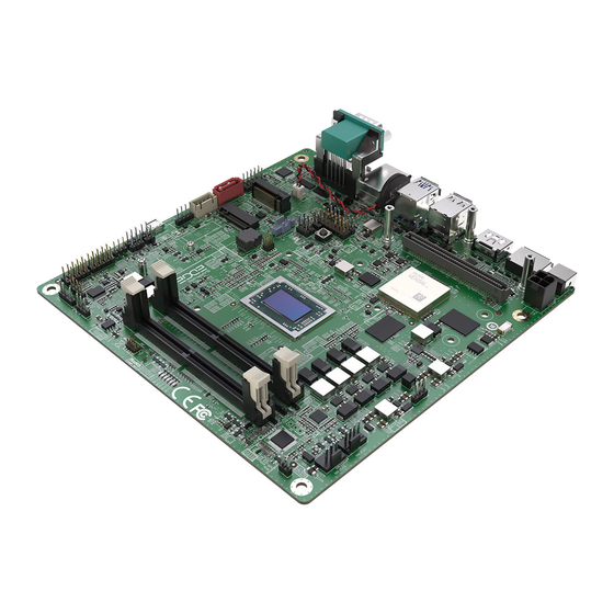
1-3 Mainboard Layout The following figure shows the location of components on the mainboard. See page 6 for component description. Note: Picture is for reference only, actual board may be slightly different. See next page for details. ~ 5 ~... - Page 12 Item Component description Location AMD FP5 APU AMD VE2302 IC DDR4 SO-DIMM *2 DIMM0/1 M.2 M-key for SSD device M.2 E-Key slot for Wifi/BT card 4-pin 12V~19V Power Connector IO Expansion Board Socket SATA3 Connector SATA Power Header, 1x4pin 2.50mm pitch SATA_PW (Note) USB 2.0 Header...
- Page 13 I/O Back Panel Item Description Item Description DC-IN 12V~19V Jack 2.5G bps RJ45 LAN Port Display Port COM Port (RS232/422/485) HDMI Port USB3.1 Type C Gen 2 Port COM1 USB2.0 Port *2 Line-Out port USB3.1 Gen 2 Port *2 Mic-In port Note: There are two ways to source power to the board: DC jack or 4-pin power connector.
-
Page 14: Mainboard Dimension
1-4 Mainboard Dimension PCB Size: 170 x 170mm ~ 8 ~... - Page 15 Mainboard with Cooler picture ~ 9 ~...
-
Page 16: Chapter 2 Installation
Chapter 2 Installation 2-1 Installing System Memory This mainboard has two 260-pin SO-DIMM sockets (ECC/Non ECC) for DDR4 memory. Supports 4GB, 8GB, 16GB and 32GB DDR4 SO-DIMMs up to maximum 64GB. Supports 1.2V DDR4-2133/2400/2666 DIMMs with dual channel architecture. Make sure that you install memory modules of the same type and density in different channel DIMM slots for Dual-Channel mode. -
Page 17: Installing Expansion Cards (Additional Purchase)
2-2 Installing Expansion Cards (Additional Purchase) IO Expansion Board Socket The mainboard provides one IO Expansion Board Socket, can be used to connect to a daughter card, like Dual Ethernet 1G card and Carmera card etc.. Note: The daughter cards are not included in standatd package contecnt. Users may want to purchase the daughter card accroding to their applications. - Page 18 Expansion Board Dimension Specification Expansion Board Outline Dimension Screw Hole Location & Dimension Connector Layout Location SEAM-40-11.0-L-04-2-A-K-TR Component Height Limit ~ 12 ~...
-
Page 19: Dual Ethernet 1G Card
Dual Ethernet 1G Card Back View Front View Connect to IO Expansion Board Dual Ethernet connector Socket of mainboard IO Expansion connector pin map Pin # I/O Bank PHY # PHY Signals Pin # I/O Bank PHY # PHY Signals +3.3V_RUN 3.3V +3.3V_RUN... -
Page 20: Camera Card
Camera Card Front View Back View PHY1 DUT RESET SW DC 12V Input connector PHY0 DUT RESET SW PHY0 LOCK/ERRB JUMPER 1-2: LOCK (Default) 2-3: ERRB Connect to IO Expansion MATE-AX connector Board Socket of mainboard PHY1 LOCK/ERRB JUMPER 1-2: LOCK (Default) 2-3: ERRB CN1 MATE-AX conn. - Page 21 Pin # I/O Bank PHY # PHY Signals Pin # I/O Bank PHY # PHY Signals +3.3V_RUN 3.3V +3.3V_RUN 3.3V LPD_MIO4_GPIO Serial I/O XPIO_L5P DA1P XPIO_L1P DA3P XPIO_L5N DA1N XPIO_L1N DA3N XPIO_L6P DB0P XPIO_L10P CKBP XPIO_L6N DB0N XPIO_L10N CKBN XPIO_L14P DB2P XPIO_L9P DB3P...
- Page 22 Dual 10/25Gb SFP28 Card Back View Front View LED1~LED4 LED1: SFP0_ACT_LED LED2: SFP0_RX_LOS_LED LED3: SFP1_ACT_LED LED4: SFP1_RX_LOS_LED Connect to IO Expansion Board Socket of mainboard SPF28 connector Mini50 connector Definition FPGA Pin Definition FPGA Pin GPI0 GPO0 GPI1 GPO1 GPI2 GPO2 GPI3 GPI4...
- Page 23 To install the SFP28 Card: 1. Align the card with the IO Expansion Board Socket, and press down on the card until it is completely seated in the slot. 2. Fasten SFP28 Card onto the nut with accompanied screws. ~ 17 ~...
-
Page 24: E-Key Slot Installation
M.2 E-Key Slot/ M.2 M-Key Slot The mainboard provides One M.2 Slot M-key (PCIe 3.0 x4 and SATA) with 2280/2580 storage type for SSD One M.2 Slot E-key (PCIe x1 and USB2.0) with 2230 type for Wifi/BT M1: M.2 M-key for M.2 SSD device LED5: When the M.2 SSD device is functional, this Green LED is blinking. -
Page 25: M-Key Slot Installation
M.2 M-Key Slot Installation To install the M.2 SSD device (type 2280/2580): 3. Remove screws and align the notch on the M.2 SSD device edge connector with the tab in the slot. 4. Plug the M.2 SSD device firmly into the slot at a 20-degree angle, and until it clicks into place. - Page 26 M.2 E-key 2230 – Supports PCIe x1 & USB2.0 based device interfaces Pin id. Pin name Description Voltage Ground +3.3V 3.3 V power supply USB_D+ USB high-, full-, and low- speed data pair positive +3.3V 3.3 V power supply USB_D- USB high-, full-, and low- speed data pair negative LED1# M2_WL_LED-...
- Page 27 M.2 M-key 2280– Supports PCIe x4 NVMe & SATA SSD Storage interfaces Pin id. Pin name Description Voltage No Connect 3.3 V Supply pin 3.3 V Ground 3.3 V Supply pin 3.3 V PERn3 PCIe Lane 3 Rx PERp3 PCIe Lane 3 Rx Ground DAS/DSS Device Activity Signal / Disable Staggered Spinup...
-
Page 28: Connecting Cables And Jumper Settings
2-3 Connecting Cables and Jumper Settings This section takes you through all the necessary connections on the mainboard. Front Panel Header The front panel header (CFP1, 2.54mm pitch) on this motherboard is used to connect the front panel switches and LEDs. PWR_LED Attach the front panel power LED cable to these two pins of the connector. -
Page 29: Sata Power Header
4-pin 12V~19V Power Connector PW1, This power connector is used to provide power to the system. Align the power plug to the connector and press firmly until seated. Definition 12V~19V 12V~19V Note: There are two ways to source power to the board: DC jack or 4-pin power connector. -
Page 30: Usb2.0 Header
USB2.0 Header This mainboard contains one 4-pin onboard header (USB2-A, 2.54mm pitch) that can be used to connect to one (1) external USB 2.0 device. Definition USB0- USB0+ COM Header The Serial port header (COM2, 2.54mm pitch) can provide one serial port via an optional COM port cable. -
Page 31: Amd Fpga Jtag Port (Internal Use Only)
AMD FPGA JTAG Port (Internal Use Only) This header (J2, 2.54mm pitch) Definition Definition +1.8V VE2302_TMS VE2302_TCK VE2302_TDO VE2302_TDI RESET- AMD APU HDT+ Header (Internal Use Only) This header (J5, 1.27mm pitch) Definition Definition +1.8V_ALW APU_TCK APU_TMS APU_TDI APU_TDO APU_TRST- APU_PWRGD RESET- APU_DBREQ-... -
Page 32: Ve2302 Gpio2 Header
VE2302 GPIO2 Header This header (J8, 2.54mm pitch) Definition FuSa_GPIO_2 AMD GPIO Header There is a GPIO (General-purpose input/output) header (J9, 2.54mm pitch) on the motherboard. It can connect a variety of simple one- or two-wire devices. Definition Definition GPIO GPIO GPIO GPIO... -
Page 33: Fan Headers
Fan Headers There are two headers (CPUFAN and SYSFAN, 2.54mm pitch) on the motherboard. These fans can be speed detected/controlled and displayed in the Hardware Health Configuration section of the CMOS Setup. The fans are automatically turned off after the system enters S3, S4 or S5 mode. Definition Note: The CPU fan cable can be either a... -
Page 34: Fuse Power Control Jumper (Jp3)
FUSE Power Control Jumper (JP3) You can use JP3 (2.54mm pitch) to select to enable or disable the FUSE Power Control function. Settings Enable Burn the FUSE Disable Burn the FUSE (Default) USB Debug Port Selection Jumper of VE2302 (JP4) The Versal AI Edge VE2302 FPGA is connected to a USB 2.0 interface via an FTDI FT4232 USB-to-JTAG/USB-UART device, providing access for debugging purposes. -
Page 35: Ve2302 Mode Selection Jumper (Jp5)
VE2302 MODE Selection Jumper (JP5) You can use JP5 (2.54mm pitch) for VE2302 MODE selection. Settings OSPI Mode (Default) JTAG Mode ROM Write Protect mode Jumper (JP6) You can use JP6 (2.54mm pitch) for ROM Write Protect mode selection. Settings Write Protect (Default) Write Operations Versal Power Control Jumper (JP7) -
Page 36: Auto Power On Jumper (Jp9)
Auto Power ON Jumper (JP9) You can use JP9 (2.54mm pitch) to select to enable or disable the auto power on function. Settings Disable. Press power button manually to power on after power input is connected to power source Enable. Automatically power on when power input is connected to power source (Default) Clear CMOS Jumper (CMOS1) -
Page 37: System Led Status Indicators
2-4 System LED Status Indicators This mainboard provides three LEDs to indicate the system’s status. STANDBY LED (LED10, Blue): When the System is in Standby Mode, this LED is on. This LED will remain on as long as the motherboard is receiving constant power. -
Page 38: Chapter 3 Configuring The Bios
Chapter 3 Configuring the BIOS This chapter provides information on the BIOS Setup program and allows you to configure the system for optimum use. 3-1 Select Boot Device Select Boot Device Menu allows you to set the first boot device without entering BIOS Setup. - Page 39 Note3: The BIOS options in this manual are for reference only. BIOS screens in manuals are usually the first BIOS version when the board is released and may be different from your purchased motherboard. Users are welcome to download the latest BIOS version from our official website.
-
Page 40: Main Menu
3-3 Main Menu When entering the Aptio Setup Utility, the main menu screen appears. This main menu includes the system overview and displays the basic system configuration, such as BIOS information, memory size and system date/time. Aptio Setup - AMI Setup Main Advanced... -
Page 41: Advanced Menu
3-4 Advanced Menu The Advanced menu items allow you to change the settings for the CPU, USB and other system devices. Press <Enter> to display the configuration options. Aptio Setup - AMI Setup Main Chipset Security Boot Save & Exit Advanced Trusted Computing Trusted Computing Settings. - Page 42 Security Device Support Enables or disables BIOS support for security device. O.S. will not show Security Device. TCG EFI protocol and INT1A interface will not be available. When enabled, the related items will appear. Options: Enabled, Disabled. SHA256 PCR Bank Enable or disable SHA256 PCR Bank.
-
Page 43: Acpi Settings
ACPI Settings Aptio Setup - AMI Setup Advanced ACPI Settings Enables or Disables BIOS ACPI Auto Configuration. Enable ACPI Auto Configuration [Disabled] Enable Hibernation [Enabled] ACPI Sleep State [S3 (Suspend to RAM)] APU ACPI Shutdown Temperature [Disabled] EuP Function [Disabled] : Select Screen ... -
Page 44: Sata Configuration
SATA Configuration Aptio Setup - AMI Setup Advanced SATA Configuration SATA Port 0 (M.2 M-Key) SAMSUNG SSD 885 (256.0GB) SATA Port 1 Not Present : Select Screen Select Item Enter: Select +/-: Change Opt. General Help Previous Values Optimized Defaults Save and Exit ESC: Exit Version 2.22.1282 Copyright (C) 2023 AMI... - Page 45 PCI-E Port XILINX Versal VE2302 (PCIE 4) Allows you to enable or disable the onboard XILINX Versal VE2302. Options: Enabled, Disabled. ASM Mode Control NB Root Port ASPM Mode Control. Options: Disabled, L0S Entry, L1 Entry, L0S and L1 Entry, Auto. Hotplug Mode Control NB Root Hotplug Mode Control.
- Page 46 ASM Mode Control NB Root Port ASPM Mode Control. Options: Disabled, L0S Entry, L1 Entry, L0S and L1 Entry, Auto. Hotplug Mode Control NB Root Hotplug Mode Control. Options: Disabled, Hotplug Basic, Hotplug Server, Hotplug Enhanced, Hotplug Inboard, Auto. Onboard 2.5 Gigabit LAN (PCIE x1) Allows you to enable or disable the onboard LAN controller.
-
Page 47: Hardware Monitor
Time of watchdog timer (second) Allows you set a period of seconds for watchdog timer. Options: 5 ~ 255 second. GPIO Header Control This sub-item is for GPIO (General-purpose input/output) header control, each GPIO is accessible via a connector pin. COM1 Mode Selection / COM2 Mode Selection Allows you to select RS232/RS485/RS422 Mode. - Page 48 Version 2.22.1282. Copyright (C) 2023 AMI. BIOS Date: 12/01/2023 14:24:53 Ver: I907W020 Press <DEL> or <ESC> to enter setup. Warning! CPU fan failure. Please check your CPU fan or enter the SETUP Hardware Monitor screen to disable fan stop spinning alarm. Press <F1>...
-
Page 49: Rtc Wake Settings
CPUFAN Speed / SYSFAN Speed Displays the current APU / System Fan Speeds. Vcore / VDDSOC / VCC3V The current voltages are automatically detected and displayed by the system. RTC Wake Settings Aptio Setup - AMI Setup Advanced Enable or disable System wake Wake system at specific Time [Disabled] on alarm event. -
Page 50: Serial Port Console Redirection
Serial Port Console Redirection Aptio Setup - AMI Setup Advanced COM1 Console Redirection Enable or Console Redirection [Disabled] Disable. Console Redirection Settings COM2 Console Redirection [Disabled] Console Redirection Settings : Select Screen Select Item Serial Port for Out-of-Band Management/ Enter: Select Windows Emergency Management Services (EMS) +/-:... -
Page 51: Cpu Configuration
CPU Configuration Aptio Setup - AMI Setup Advanced CPU Configuration Enable/disable the generation of APCI_PPC, _PSS, and _PCT Module Version: PiccasoCpu 10 objects. AGESA Version: Embedded-FP5 PI 1206RC1 PSS Support [Enabled] PPC Adjustment [PState 0] NX Mode [Enabled] : Select Screen ... -
Page 52: Sio Configuration
CPU Information Displays current processor information. Aptio Setup - AMI Setup Advanced Socket0: AMD Ryzen Embedded R2314 with Radeon Graphics 4 Core(s) Running @ 2129 MHz 1218 mV Processor Family: 17h Processor Model: 10h-1Fh CPUID: 00810F81 Current Speed:2100 MHZ Min Speed:1400 MHZ Microcode Patch Level: 8108109 -------------- Cache Per Core -------------------- L1 Instruction Cache: 64 KB/4-way... -
Page 53: Pci Subsystem Settings
PCI Subsystem Settings Aptio Setup - AMI Setup Advanced PCI Bus Driver Version: A5.01.26 Value to be programmed into PCI Latency Timer Register. PCI Devices Common Settings: PCI Latency Timer [32 PCI Bus Clocks] PCI-X Latency Timer [64 PCI Bus Clocks] VGA Palette Snoop [Disabled] PERR# Generation... -
Page 54: Usb Configuration
Above 4G Decoding Enable or disable 64bit capable device to be decoded in above 4G address space (only if system supports 64bit PCI decoding). Options: Enabled, Disabled. SR-IOV Support If system has SR-IOV capable PCIe devices, this option enables or disables Single Root IO Virtualization support. - Page 55 Legacy USB Support Allows you to select legacy support for USB devices. Enabled: Enables Legacy USB support. Disabled: Keep USB devices available only for EFI application. Auto: Disables legacy support if no USB devices are connected. XHCI Hand-off This is a workaround for OSes without XHCI hand-off support. The XHCI ownership change should be claimed by XHCI driver.
-
Page 56: Network Stack Configuration
Network Stack Configuration Aptio Setup - AMI Setup Advanced Enable/Disable UEFI Network Network Stack [Disabled] Stack : Select Screen Select Item Enter: Select +/-: Change Opt. General Help Previous Values Optimized Defaults Save and Exit ESC: Exit Version 2.22.1282 Copyright (C) 2023 AMI Network Stack This item is used for network boot in UEFI mode. -
Page 57: Csm Configuration
PXE boot wait time This item is used to set a wait time in seconds for PXE boot. Press ESC key to abort the PXE boot. Options: 0~5 sec. Media detect count Number of times presence of media will be checked. CSM Configuration Aptio Setup - AMI Setup... -
Page 58: Nvme Configuration
messages. Option ROMs requiring interactive inputs may not work properly in this mode. INT19 Trap Response This item allows BIOS reaction on INT19 trapping by option ROM. Immediate: Execute the trap right away. Postponed: Execute the trap during legacy boot. HDD Connection Order Some OS require HDD handles to adjusted, i.e. -
Page 59: Amd Cbs
AMD CBS Aptio Setup - AMI Setup Advanced AMD CBS Zen Common Options Zen Common Options DF Common Options UMC Common Options NBIO Common Options : Select Screen FCH Common Options Select Item Enter: Select +/-: Change Opt. General Help Previous Values Optimized Defaults Save and Exit... - Page 60 Core/Thread Enablement Allows you set the Core/Thread Enablement. S3 is NOT SUPPORTED on systems where cores/threads have been removed/disabled. Options: Disagree, Agree. Streaming Stores Control Allows you enable or disable the streaming stores functionality. Options: Enabled, Disabled, Auto. Enable IBS When IBS is enabled, SpecLockMap and Stack Engine are disabled.
- Page 61 Location of private memory regions Controls whether or not the private memory regions (PSP, SMU and CC6) are at the top of DRAM or distributed. Note that distributed requires memory on all dies, it will always be at the top of DRAM if some dies don’t have memory regardless of this option’s setting.
- Page 62 UMC Common Options DDR4 Common Options DRAM Timing Configuration Aptio Setup - AMI Setup Advanced DRAM Timing Configuration I Accept WARNING - DAMAGE CAUSED BY USE OF YOUR AMD PROCESSOR OUTSIDE OF SPECIFICATION OR IN EXCESS OF FACTORY SETTINGS ARE NOT COVERED UNDER YOUR AMD PRODUCT WARRANTY AND MAY NOT BE CONVERED BY YOUR SYSTEM MANUFACTURE’S WARRANTY.
- Page 63 DRAM Control Configuration DRAM Power Options Power Down Enable Allows you to enable or disable DDR power down mode. Options: Enabled, Disabled, Auto. Gear Down Mode Allows you to enable or disable gear down mode. Options: Enabled, Disabled, Auto. Data Mask Allows you to enable or disable data mask.
- Page 64 Disable Memory Error Injection Use this option to control Disable Memory Error Injection. Options: False, True. DRAM Memory Mapping Chip select Interleaving Interleave memory blocks across the DRAM chip selects for node 0. Options: Disabled, Auto. BankGroupSwap Use this option to control BankGroupSwap. Options: APU, CPU, Disabled, Auto.
- Page 65 processor. Options: Auto, 64M, 80M, 96M, 128M, 256M, 384M, 512M, 768M, 1G, 2G, 3G, 4G, 8G, 16G. Display Resolution This item will only appear when “UMA Mode” item is set to “UMA_AUTO” option. It allows you select the display resolution. Options: 1920x1080 and below, 2560x1600, 3840x2160, Auto.
- Page 66 upper/highest Embedded system configuration supported for an Embedded Rayzen part. Options: 12W POR Configuration 15W POR Configuration 25W POR Configuration 35W POR Configuration Auto. Warning: Select System Configuration may cause the system to hang, as some System Configuration may not be supported by your OPN. System Temperature Tracking This item allows you to select the System Temperature Tracking.
-
Page 67: Amd Pbs
AMD PBS Aptio Setup - AMI Setup Advanced AMD Firmware Version Show all of AMD Firmware Version : Select Screen Select Item Enter: Select +/-: Change Opt. General Help Previous Values Optimized Defaults Save and Exit ESC: Exit Version 2.22.1282 Copyright (C) 2023 AMI AMD Firmware Version Show all of AMD Firmware Version. -
Page 68: Chipset Menu
3-5 Chipset Menu The chipset menu items allow you to change the advanced chipset settings. Press <Enter> to display the sub-menu. Aptio Setup - AMI Setup Main Advanced Security Boot Save & Exit Chipset South Bridge Parameters South Bridge North Bridge : Select Screen ... - Page 69 USB3.2 TYPE-C Port / USB2.0 HUB Allows you to enable or disable USB ports. Options: Enabled, Disabled. North Bridge Aptio Setup - AMI Setup Chipset North Bridge Configuration View Information related to Socket 0 Memory Information Total Memory: 32768 MB (DDR4-2667) Memory Information Select Screen ...
-
Page 70: Security Menu
3-6 Security Menu The Security menu allows you to change the system security settings. Aptio Setup - AMI Setup Main Advanced Chipset Boot Save & Exit Security Password Description Set Administrator Password. If ONLY the Administrator’s password is set, then this only limits access to Setup and is only asked for when entering Setup. -
Page 71: Boot Menu
3-7 Boot Menu The Boot menu is used to configure the boot settings and the boot priority. Aptio Setup - AMI Setup Main Advanced Chipset Security Save & Exit Boot Boot Configuration Number of seconds to wait for Setup Prompt Timeout setup activation key. -
Page 72: Save & Exit Menu
3-8 Save & Exit Menu The Save & Exit menu allows you to load the optimal default values for BIOS, and save or discard your changes to the BIOS items. Aptio Setup - AMI Setup Main Advanced Chipset Security Boot Save &... -
Page 73: Chapter 4 Firmware And Driver Installation
Chapter 4 Firmware and Driver Installation After the operating system has been installed, you need to install the software and drivers for this mainboard. The OSPI firmware may also need to be updated. Please visit http://www.sapphiretech.com or http://www.amd.com to download the latest driver. ~ 67 ~... -
Page 74: Chapter 5 Chassis Installation
Chapter 5 Chassis Installation Follow the instructions below to install the mainboard into the chassis. Remove the 2 screws on back of chassis to open the cover of chassis. Remove the 2 screws of SATA bracket to take out the SATA bracket. Place the I/O shield on back of chassis first. - Page 75 Fasten SATA bracket to chassis with 2 screws of SATA bracket. Fasten chassis cover to chassis with 2 screws of chassis. The system installation is complete. ~ 69 ~...
-
Page 76: Appendix A: Bios Update
Appendix A: BIOS Update Please refer the following steps for BIOS update. Please download the latest BIOS version from this link. www.sappphire.com/xxxxxxxxxxxxxx After downloading the compressed file, there are four files upon extracting the archive. Open a terminal window in this folder and execute the command # sudo ./flash.sh Update completed, as shown in the following picture. -
Page 77: Appendix B: Qualified Vendors List
Appendix B: Qualified Vendors List Qualified Vendors List for Memory modules DDR4 2133 Memory modules DIMM socket support Vendor Module P/N Size Component Voltage 1 DIMM 2 DIMM ADATA AD4S2133W4G15-BSSD K4A4GO85WD 1.2V GeIL GS44GB2133C15SC GeIL 512X8DDR4 1.2V ... - Page 78 DDR4 2666 Memory modules DIMM socket support Vendor Module P/N Size Component Voltage 1 DIMM 2 DIMM Team Elite TEAMGROUP TED44G2666C19-SBK 1.2V TD5128KT-266 SMART SH1026SO410893-SC SWT0A10805383FC175 1.2V SEC 843 K4A8608 5WC SAMSUNG M471A1K43CB1-CTD 1.2V BCTD ...
- Page 79 Qualified Vendors List for SSD M.2 SSD Vander Model / PN Interface Capacity 2280 Form factor <NVME> ADATA XPG GAMMIX S70 BLADE PCIE Gen 4 x4 Kingston NV2 SNV2S250G PCIe Gen 4 x4 250GB Samsung PM9B1 MZ-VL41T00 PCIe Gen 4 x4 Teamgroup T-FORCE TMBFPL250G PCIe Gen 4 x4...
- Page 80 Qualified Vendors List for WIFI+BT Vander Model Intel AX210 WIiFi 6E Intel 9260NGW Intel 8260NGW Intel 3165NGW MediaTek MT7922 WIFI-6E (RZ616) Realtek RTL8852BE ~ 74 ~...
-
Page 81: Appendix C: Expansion Board & Connector
Appendix C: Expansion Board & Connector Expansion Connector The expansion connector is high-speed interface for specific peripherals such as cameras or high speed networking. The signals and pin numbers of connector are provided in the following Table. Type Signal Count High Speed transceivers GTYP 20 (10 diff-pairs) - Page 82 Power Enable (VCC_CARD_EN) A power enable (VCC_CARD_EN) signal is routed from the Versal device to the expansion card to be used by the local expansion card local power supplies. This signal used to gate the HDIO_VCCO and XPIO_VCCO power supplies. The HDIO_VCCO and XPIO_VCCO power supplies should remain low until the PWR_EN signal goes high.
- Page 83 SelectIO standard for XPIO Banks : DC Input and Output Levels Complementary Differential SelectIO standard for HDIO Banks : DC Input and Output Levels Complementary Differential SelectIO standard for XPIO Banks : DC Input and Output Levels ~ 77 ~...
- Page 84 Differential SelectIO standard for MIPI_DPHY : DC Input and Output Levels GTYP Transceiver : DC Input and Output Levels GTYP Transceiver Clock Output Level Specification Symbol Description Conditions Min Typ Max Units Output Low voltage for P and N RT = 100Ω...
- Page 85 PCB Routing Constrains for Daughter Board Signal name impedance Max Length space Length Matching and note VCC_CARD_EN LPD_MIO4_GPIO 50 ohm 5” 3H * HDIO[0..21] Difference between P and N traces GTYP_CLKP/N[0..1] 85 ohm 3” within a differential pair 0.75ps Difference between P and N traces GTYP_TXP/N[0..3] within a differential pair 0.5ps 85 ohm...
Need help?
Do you have a question about the EDGE+ VPR-4616-MB and is the answer not in the manual?
Questions and answers