Advertisement
Available languages
Available languages
Quick Links
INSTALLATION MANUAL
Level of Difficulty
Easy
Installation difficulty levels are based on time
and effort involved and may vary depending on
the installer level of expertise, condition of the
vehicle and proper tools and equipment.
Electrical Ratings
Signal circuits
3.0-amps per side
Tail / Running Circuits
6.0-amps total
Check vehicle owner's manual or contact
the vehicle manufacturer for more information.
Wiring Location(s)
S3 and S4
Wiring Location Guide*
for SUVs and Vans (S)
S1
Behind driver side taillight housing
S2
Behind passenger side taillight housing
S3
Behind driver side rear access panel
S4
Behind passenger side rear access panel
S5
Behind driver side rear bumper
S6
Behind center of rear bumper
S7
Behind passenger side rear bumper
S8
Under rear floor panel
S9
Behind driver side rear access panel
S10 Behind passenger side rear access panel
S10
S9
S1
S2
S3
S4
S8
S5
S6
S7
* Representative vehicle shown
Tools Required
Ratchet
Panel trim
removal tool
Socket, 10mm
Cutting tool
Socket extension
Wire crimper
Phillips screwdriver
Wire stripper
Flathead screwdriver Electrical tape
56487-INS-RA
•
03/01/2023
•
WARNING
Do not exceed product rating or tow vehicle lamp load rating, whichever is lower.
The battery connection must be fuse-protected, 10-amp max. Exceeding
the product rating can cause loss of warranty, overheating and potential fire.
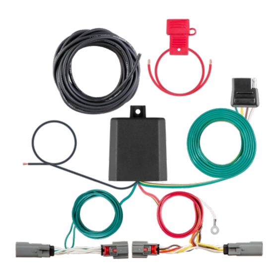
Product Photo
Hardware Photo
NOTICE
Before you begin installation, read all instructions thoroughly.
Proper tools will improve the quality of installation and reduce the time required.
All steps must be followed to ensure the product will function properly. Once installed,
test for proper function by using a test light or connecting a properly wired trailer.
Maintenance
Periodic inspection of all wires and connections should be performed
to ensure there is no visible damage or loose connections.
ECN10588
•
PAGE 1 OF 5
Advertisement

Related Manuals for Curt Manufacturing 12170


Summary of Contents for Curt Manufacturing 12170
- Page 1 INSTALLATION MANUAL Level of Difficulty WARNING Do not exceed product rating or tow vehicle lamp load rating, whichever is lower. Easy The battery connection must be fuse-protected, 10-amp max. Exceeding Installation difficulty levels are based on time and effort involved and may vary depending on the product rating can cause loss of warranty, overheating and potential fire.
- Page 2 Step 1 Locate the vehicle battery and disconnect the negative battery terminal. Be sure to fasten this wire down and away from the battery while completing the installation process. Step 2 Open the rear hatch. Remove all floor coverings and storage trays. Step 3 Remove the fasteners securing each side of the rear scuff panel.
- Page 3 Step 4 Starting on the driver side, remove the push fasteners and cargo tie down located at the rear of interior side trim panel. Remove the Phillips screw from the rear seat release. Step 5 Remove the Phillips screw located at the front upper side of the interior side trim panel.
- Page 4 Step 7 Behind the side trim panel, locate the vehicle taillight wiring harness connectors. The connectors will be similar to those on the custom wiring harness. Separate the connectors from the taillight housing taking care not to damage the locking tabs. Step 8 Insert the custom wiring harness end with yellow wire between the separated connectors.
- Page 5 POWERED CONVERTER LEAD INSTRUCTION SHEET FICHE DE CONSIGNES DU CONVERTISSEUR D'ALIMENTATION HOJA DE INSTRUCCIONES DEL CONDUCTOR DEL ADAPTADOR ALIMENTADO POR BATERÍA NOTICE WARNING AVIS / AVISO AVERTISSEMENT / ADVERTENCIA Illustrations are for reference only. Battery To avoid personal injury or property damage, check for miscellaneous location may differ depending on the vehicle.
Need help?
Do you have a question about the 12170 and is the answer not in the manual?
Questions and answers