Sign In
Upload
Manuals
Brands
Hioki Manuals
Measuring Instruments
BT4560-50
Hioki BT4560-50 Manuals
Manuals and User Guides for Hioki BT4560-50. We have
2
Hioki BT4560-50 manuals available for free PDF download: Instruction Manual
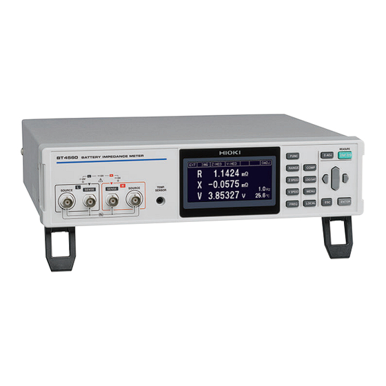
Hioki BT4560-50 Instruction Manual (167 pages)
BATTERY IMPEDANCE METER
Brand:
Hioki
| Category:
Measuring Instruments
| Size: 13 MB
Table of Contents
Table of Contents
2
Introduction
6
Verifying Package Contents
6
Safety Information
8
Operating Precautions
11
Overview
18
Product Overview and Features
18
Names and Functions of Parts
19
Screen Configuration and Operation
22
X84; Measurement Screen
22
X84; Settings Screen
22
Measurement Flow
23
Preparation
24
Connecting the Power Cord
24
Connecting the Measurement Probe and Temperature Sensor (Optional)
25
X84; Connect the Four-Terminal Cable to the Instrument
25
X84; Connect the Temperature Sensor to the Instrument
25
Turning the Power on or off
26
Inspection before Use
26
Basic Measurement
28
Selecting the Measurement Functions
28
Selecting the Measurement Range
29
Setting the Measurement Speed
30
Setting the Measurement Frequency
31
X84; When the Measurement Time Is Long (Display of the Progress Bar)
32
Performing the Zero Adjustment
33
X84; Performing the Zero Adjustment
33
X84; Connection When Performing the Zero Adjustment
36
Checking the Measurement Results
37
X84; Detecting the Measurement Abnormality
37
X84; Temperature Measurement Indication
39
X84; Overrange Indication
39
Basic Measurement Examples
40
Customization of Measurement Conditions
44
Setting the Measurement Starting Conditions (Trigger Functions)
44
X84; Setting the Trigger
44
X84; Inputting the External Trigger
45
Starting the Measurement after the Response of the Measuring Object Is Stable (Sample Delay Function)
45
Maintaining Voltage Measurement Accuracy (Self-Calibration Function)
48
Stabilizing the Measurement Values (Average Function)
49
Compensating the Potential Slope Due to Electric Discharge (Slope Correction Function)
50
Preventing the Overcharge Due to Measurement Signal (Voltage Limit Function)
52
Prevents Charging and
54
Measurement Signal
54
Cross Stop Function)
54
Judging Measurement Results (Comparator Function)
56
Turning the Comparator Function on and off
57
Setting the Upper and Lower Limit Value
58
Voltage Is Judged with the Absolute Value
61
Checking the Judgment with Sound
62
Checking the Judgment Result
63
Saving and Reading Measurement Conditions (Panel Saving and Loading)
64
Saving the Setting Conditions (Panel Saving Function)
65
Reading the Setting Conditions (Panel Loading Function)
67
Deleting the Contents of the Panel
68
System Setting
70
Making the Key Operation Effective or Ineffective
70
Setting the Sound of the Key Operation Effective or Ineffective
72
Adjusting the Contrast of the Screen
73
Adjusting the Backlight
74
System Testing
75
Confirm Instrument Information
80
Initializing (Reset)
81
X84; Initial Setting Table
83
External Control (EXT.I/O)
86
External Input/Output Terminals and Signals
87
X84; Switching the Current Sink (NPN) /The Current Source (PNP)
87
X84; Arranging the Usage Connector and the Signals
87
X84; Functions of each Signal
89
Timing Chart
91
X84; Acquiring the Judgment Results after Starting Measurement
91
X84; Timing of the Zero Adjustment
94
X84; Timing of the Self-Calibration
94
X84; Timing of the Panel Loading
96
X84; Output Signal Status When Turning on the Power Supply
96
X84; Taking-In Flow with the External Trigger
97
Internal Circuitry
98
X84; Electrical Specifications
99
X84; Examples of Connection
100
Checking the External Control
101
X84; Testing the Inputs/Outputs (EXT.I/O Testing Functions)
101
Communication (RS-232C, USB, LAN)
102
Features of Interface
102
X84; Specifications
102
Connecting and Setting Method
104
X84; Selecting an Interface (BT4560-50 Only)
104
X84; Using the USB Interface
105
X84; Using the RS-232C Cable
106
X84; Setting the Transmission Speed (Common for USB, RS-232C)
107
X84; Using the LAN Interface (BT4560-50 Only)
108
X84; Setting LAN Communications (BT4560- 50 Only)
109
X84; Outputting Measured Values after Measurement Completes
112
Controlling the Communication and Acquiring the Data
113
X84; Remote State/Local State
113
Specifications
114
Specifications of Measurement Functions
114
Additional Function
117
User Interface
123
External Interface
123
Accuracy
125
General Specifications
128
X84; Standards
129
X84; Accessories
129
X84; Options
129
Maintenance and Service
130
Troubleshooting
130
X84; Q&A (Frequent Inquiries)
130
X84; Error Display and Remedy
134
Inspection, Repair and Cleaning
136
Discarding the Instrument
137
X84; Lithium Battery Removal
137
Appendix
138
Appx. 2 Four-Terminal Pair Method
139
Your Own Measurement Probe
141
Structure and Extension
143
Measurement Value Due
144
Appx. 6 Influence Of The Eddy Current A8
145
Appx. 7 Zero Adjustment
145
Appx. 8 Measurement Probe (Option) A12
149
Making the Switching Unit
150
Measuring the Battery
152
Appx. 11 Calibrating the Instrument
155
Appx. 12 Rack Mounting
157
Appx. 13 Dimensional Diagram
159
Using PC Application Softwares
161
Appx. 15 License Information
162
Advertisement
Hioki BT4560-50 Instruction Manual (60 pages)
BATTERY IMPEDANCE METER
Brand:
Hioki
| Category:
Measuring Instruments
| Size: 1 MB
Table of Contents
Table of Contents
2
1 Introduction
4
Message Format
4
Output Queue and Input Buffer
8
Status Byte Register
9
Event Registers
11
Initialization Items
14
Local Function
14
Command Execution Time
15
Errors During Communications
15
2 Message List
16
3 Message Reference
19
Message Reference Interpretation
19
Standard Commands
20
System Data Command
20
Idn
20
Internal Operation Command
20
Tst
20
Synchronization Commands
21
Opc
21
Wai
21
Status and Event Control Commands
21
Cls
21
Ese
22
Esr
22
Sre
23
Trg
24
Device-Specific Commands
24
Instrument Model Name
24
Qpid
24
Event Status Register
24
Ese0
24
Esr0
25
Ese1
25
Esr1
25
Measurement Functions
26
Measurement Frequency
26
Frequency
26
Measurement Range
27
Range
27
Sampling Speed
27
Sample Delay
28
Sample:delay:voltage
28
Potential Slope Correction
29
Adjust:slope
29
Voltage Limit
29
Limiter
29
Limiter:voltage
29
Measurement Signal Zero Cross Stop
29
Averaging
30
Calculate:average
30
Zero Adjustment
30
Adjust:clear
30
Self-Calibration
33
Calibration
33
Calibration:auto
33
Comparator
33
Calculate:limit:state
33
Calculate:limit:beeper
33
Calculate:limit:abs
34
Calculate:limit:resistance
34
Calculate:limit:reactance
35
Saving and Reading Measurement Conditions
37
Save/:Load
37
Save:clear
37
System Reset
37
Measured Value Output
37
System:dataout
37
Key Beeper
38
Key-Lock
38
System:klock
38
Communications Settings
38
Header
38
System:header
38
Serial Number
39
LCD Settings
39
System:display:backlight
39
Triggering
40
Initiate:continuous
40
Trigger:source
40
Initiate
42
Reading Measured Values
43
Abort
44
Measure:valid
44
Fetch
45
Read
46
4 Data Exporting Methods
47
5 Sample Programs
49
Using Visual Basic 5.0 or 6.0
49
RS-232C/USB Communications (Using Microsoft Visual Basic Professional Mscomm)
49
Simple Measurement
49
Measure by PC Key
50
External Trigger Measurement
51
Set Measurement Conditions
52
Using Visual Basic2013
53
Advertisement
Related Products
Hioki BT4560
Hioki BT3562-01
Hioki BT3562
Hioki BT3563-01
Hioki BT3563
Hioki BT3554
Hioki BT3554-01
Hioki BT3554-10
Hioki BT3564
Hioki BT3554-51
Hioki Categories
Measuring Instruments
Test Equipment
Data Loggers
Multimeter
Accessories
More Hioki Manuals
Login
Sign In
OR
Sign in with Facebook
Sign in with Google
Upload manual
Upload from disk
Upload from URL