
Related Manuals for DINKO Instruments D-600/353Y


Summary of Contents for DINKO Instruments D-600/353Y
- Page 1 DIGITAL PERISTALTIC DOSING PUMP Model D-600/353Y Code 1.9754.00 MANUAL February 2024 Marked c/ Encarnació , 123 -125. Tel. +34 93 284 69 62. Fax +34 93 210 43 07 e-mail: dinter@dinko.es www.dinko.es 08024 – Barcelona...
-
Page 2: Table Of Contents
INDEX Page 1. GENERAL INTRODUCTION. ······································································ 4 2. KNOW THE PERISTALTIC PUMP. ······························································· 5 3. RECEPTION. ··························································································· 6 4. DESCRIPTION AND PUMP HEAD. ······························································ 7 5. CHANGE OF TUBES. ·············································································· 10 6. HOW TO USE. ························································································ 12 7. SPECIFICATIONS. ·················································································· 30 8. - Page 3 Security Please read this manual carefully before use! ●To avoid fire or electric shock, please do not use the pump outdoors, or in a humid environment. ●To reduce the risk of electric shock and the possibility of damage to the equipment, please use a standard 220 VAC grounded plug.
-
Page 4: General Introduction
1. GENERAL INTRODUCTION. Peristaltic pumps pump all kinds of liquid substances without coming into contact with the mechanical elements as in other pumps. They are easy to use with minimal maintenance. The pumped substance is propelled into an elastic tube by the vacuum generated by rotors that successively press and release the surface of the tube. -
Page 5: Know The Peristaltic Pump
2. GET TO KNOW THE PERIST ALTIC PUMP. The 600 series peristaltic pumps are intelligent pumps that combine flow, timing and filling dosing functions. They can be operated by buttons, or controlled by an external signal or foot switch. They have a full speed emptying function and you can adjust the suction angle, etc. -
Page 6: Reception
3. RECEPTION. To guarantee correct reception, use of the device, and the safety of the user, we recommend reading this manual in detail before proceeding to unpack the device and subsequent use and especially the following points: 3.1- THE MANUAL. This manual must be kept permanently within reach of the user of the equipment. -
Page 7: Description And Pump Head
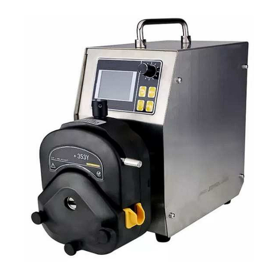
4. DESCRIPTION AND PUMP HEAD. The D-600/353Y peristaltic pumps in this manual mount the 353Y single-channel head, which allows the tube to be easily removed, for its extraction when it must be replaced due to tube wear or for the use of another tube with a different interior diameter. - Page 8 353Y Pump head and pump tube. 1- Moving head body. 2- Fixed head body. 3- Head release lever. 4- Upper control to adjust the pressure of the head on the tube. 5- Tube guides. 6- Fixing holes for the complementary head. To install the tube in the peristaltic pump head, follow these three steps: Step 1: Turn the lever counterclockwise to lift the top clamp.
- Page 9 Finally, to make a fine adjustment of the pressure of the head on the tube, place the tube in its position and turn the upper control completely to the left. Now start the pump, if there is no liquid circulation through the tube, slowly turn the upper control clockwise until you see how the liquid begins to circulate through the tube.
-
Page 10: Change Of Tubes
5. CHANGE OF TUBE. Press the OFF switch. Extract the tube according to the instructions described in the “Description” and “Head” sections. When the new tube is installed, it must be centered over the rollers to prevent the rotor from pinching it. Check that the pump is OFF. - Page 11 AVAILABLE MATERIALS: PHARMA Autoclavable multiple times. Sterilizable by ETO and Gamma . Food-medical grade, USP class VI, 21CFR 177.2600 and FDA. Not hemolytic. Excellent resistance to chemicals. ISO 10993. Low permeability and good abrasion resistance. Long duration. Use temperature, -51ºC to 132ºC Beige.
-
Page 12: How To Use
6. HOW TO USE. 6.1 Front panel description: Screen ( Screen ): where the different menus are displayed. Knob (K): It is the button for selecting and configuring all parameters. With the external control activated the button (K) is only used for function selection. - Page 13 6.3 Starting the pump. Switch Turn on the pump with the red switch located on the back. The peristaltic pump has a power-off memory function. If when we turn off the pump, we do so by holding down the Start /Stop button (S), it memorizes the last established Mode, which will be the mode that will appear when we turn on the peristaltic pump again.
- Page 14 Main menu: By pressing the selection button (K) for three seconds, we will enter the main menu. Description of the different sections: 1- Mode : Where we select the work mode. 2- Parameter : We configure the characteristics of the pump. 3- Timing: To configure this working mode.
- Page 15 2. Parameter . This section consists of two screens. 2.1. Pump Head: Here we choose which head the pump is working with, by default it is already configured with the head it mounts. 2.2. Tube type : Here we can choose which tube we are going to work with, depending on the chosen head, the different tube sizes that we can use with the chosen head will appear, we select the one we are going to work with.
- Page 16 2.4. Suck Back: In this section we activate the anti-drip function, we choose the degrees that the motor will rotate in the opposite direction at the end of the dosage. 2.5. Real Time: To adjust the device's time. To go to the second Parameter screen , we turn the knob (K) to the right. 2.6.
- Page 17 2.7. External control: Here we can select whether or not we are going to use external control. 2.8. Control type: We can select between different types of external control 0 -5 V, 0-1 V, 4-20 mA or RS485. Once all the parameters have been configured correctly, we are going to select which work mode we are going to use.
- Page 18 We select 1. Mode by pressing the selection knob (K), the three work modes will By turning the selection knob (K), we choose which working mode we are going to use: Timing: When we press the selection knob (K) on Timing, it will take us to the 3.Timing menu of the main menu and show us the different parameters to configure.
- Page 19 3.Timing 3.1. Delay : Here we can enter the waiting time before starting to dose. We choose the time in hours: minutes: seconds (00:00:00), we move between the different sections, we press the control (K) and by turning it we raise or lower the different values. 3.2.
- Page 20 3.4. Frequency : We can indicate how many times we want the dosage to berepeated. 3.5. Flow: We select the flow in ml/min that we want the pump to work with, always with the limitation that we have due to the tube we are using. All sections must have some digit, except the initial waiting time, which can be zero.
- Page 21 Speed : With this mode we will control the pump flow rate by the motor speed. It is used to transfer or fill a bottle manually. When we press the selection knob (K) on Speed , Parameter appears , as we have already programmed it, we do not touch anything.
- Page 22 Filling : We will use this mode for dosages, both single and multiple. When we press the selection knob (K) on Filling , it will take us to the 4.Filling menu of the main menu and show us the different parameters to configure. 4.Filling 4.1.
- Page 23 4.3 Pause : Here you enter the waiting time between doses, confirm by pressing the selection knob (K). This section must have some value, even if you want a single dosage, for example 1 second. 4.4 Frequency : In this section We can choose the number of doses to be carried out, you can choose between 1 and 90,000, always program at least one dose, confirm by pressing the selection knob (K).
- Page 24 5. Review . The pump is factory calibrated for silicone tubes and clean water at a temperature of 20ºC on a horizontal surface and a tube length of 1 meter. This section of the menu helps us recalibrate the pump for certain working conditions. We will enter this section once we have configured the Parameter menu .
- Page 25 It allows us to modify the time and speed, the volume will vary automatically. Confirm by pressing (K), the following screen appears with the volume to measure. We press (S) and measure the volume supplied. We enter the actual measured value by turning the knob (K) and confirm by pressing.
- Page 26 5. Traffic Correction : To enter this section we select Mode from the main menu, select Speed and confirm by pressing (K). Press (R), we enter the main menu and select Review and press (K). Appears on screen Traffic Correction. It allows us to modify the time and speed, the volume will vary automatically.
- Page 27 We enter the actual measured value by turning the knob (K) and confirm by pressing. You will return to the previous screen with the speed and flow modified. 5. Filling Correction : To enter this section we select Mode from the main menu, select Filling and confirm by pressing (K).
- Page 28 Filling appears on the screen Correction , with the values that will perform the calibration, which are those of three dosages, to average. If correct, confirm the values by pressing (K) The value that will be dosed appears on the screen, which will be three times that of a dosage.
- Page 29 Appears with the modified speed. We press (R) and it will return to the main menu.
-
Page 30: Specifications
7. SPECIFICATIONS . Table of indicative flow rates with 353Y head Item/Code 353Y /1.9754.00 Speed range 30 – 600 rpm Maximum speed 600 rpm 1 rpm Speed resolution Maximum suction 0.17MPa vacuum Maximum outlet 0.17MPa pressure Membrane keyboard Control mode Manual control, automation, timing, filling, external Principal function control... -
Page 31: Ordering Information
All initiatives must be carried out by qualified personnel to avoid greater harm. Entrust your device to a technical service authorized by DINKO Instruments. The engine and its block do not require lubrication so they are maintenance-free. The rotor bearings are self-lubricating, but it is advisable to lubricate them lightly with silicone grease ref. -
Page 32: Accessories
10. ACCESSORIES . 10.1 Scale for calibration of flow rates and dosages . Reproducibility 0.01 g. Capacity 500g. Code 1.9812.04 To measure the dosed quantity in the Calibration process of peristaltic pumps, it is very effective to use a precision scale with digital reading. - Page 33 10.5 Reducing Connectors - Splice/Equal Ends, Polypropylene For tubes with 1.6/3.2 mm ID. Code1.0080.15 For tubes with 3.2/4.8 mm ID. Code 1.0080.18 For tubes with 4.8/6.4 mm ID. Code 1.0080.05 For tubes with 6.4/8 mm ID. Code 1.0080.14 For 8/12.7mm ID tubes. Code 1.0080.20 10.6 Straight connector for splice/reducer, polypropylene Straight connector / reducer Ø...
- Page 34 10.9 Anti floats 304 stainless steel for suction tubes. For peristaltic tubes with 1.6 and 3.2 mm ID. Code1.0303.10 For peristaltic tubes with an ID of 4.8 mm. Code 1.0303.11 For peristaltic tubes with an ID of 6.4 mm. Code 1.0303.12 For peristaltic tubes with an ID of 8.0 mm.
-
Page 35: Change Of Fuses
11. CHANGING FUSES. The fuse holder box is part of the power supply base located at the back of the pump. See Figure. Fuse holder box Power base Pry with a screwdriver between the central part of the fuse holder box and the top part of the power supply base to remove the fuse holder box. -
Page 36: Maintenance
12. MAINTENANCE. 1) Before each start of the peristaltic pump, carefully check whether the tube is damaged. Before the machine stops working, please pump water to clean the tube. To extend the life of the tube, especially after running at high speed (100 rpm or more) for 8 hours, the tube should be pulled out (suction end) 80 to 100 mm to prevent the tube from shifting, being crushed in a certain fixed point due to the compression of the tube by the roller and damage to the tube due to excessive wear or bending... -
Page 37: Troubleshooting
13. TROUBLESHOOT Item Problem Inspection Treatment Observation Screen without Check the Built-in insurance Plug on or not display line in the socket Check Correct or incorrect settings and control reboot Pump head High pressure. Tube too tight Adjust Normal screen or not display, but pump Tube size suitable for... -
Page 38: Packing List
14. PACKING LIST Article Name Unit Amount Observation Smart drive 253Yx pump head Power cord Foot switch 15 pin male connector 15-pin female connector Silicone tube meter Manual Warranty card... -
Page 39: Annexes
TO NEXOS. Annex 1 BT-CA series control mode Manual Foot switch (pulse or lever for option) Speed External signal (0-5V, 0-10V, 4-20Ma, Modbus) Key Start/stop to start timing program have been Timing Mode Start/stop by on/off signal of foot switch etc. Key Start/stop to start timing program have been Filling Start/stop by on/off signal of infrared, foot switch... - Page 40 Annex 2 Definition of external control terminal Definition of input terminal 1) ON/OFF is start and stop control, CW/CCW is positive and negative control. For external control switch, short circuit or hung up to control. 2) GND is ground, which is the ground of the external control input signal. 3) When the pump is operated using the foot switch or value switch, Please short circuit the terminal ⑨...
- Page 41 Annex 3 DB15 External wiring Annex 3 DB15 External wiring External control mode 1: 0 ~ 5V External control mode 2: 0 ~10 V External control mode 3: 4~20 External control mode 3: 4 ~20mA...
- Page 42 Annex 3 DB15 External wiring External control mode 4: Modbus – rtu Foot switch Infrared switch 1. Use external control mode, 1-4 to enable external control and select the corresponding external control mode. 2. When using a switch such as a foot switch or infrared, it is necessary to ensure that the external control is turned off.
- Page 43 Annex 4 Modbus Parameter Article Content Communication rtu standard communication protocol , baud rate 9600, 8 data format data bits, 1 stop bit, even parity check. Command code Modbus- rtu uses the command code 02,04,06,15, the done starting addresses are all 999. Command 02 bit address 999 is start/stop signal, 1 for 02 discrete signal start, 0 for stop.
-
Page 44: Warranty
16. WARRANTY . 16.1 DURATION The warranty is established for a period of 1 year from the date of commissioning of the device as long as the warranty card is returned to us within 8 days following said commissioning. Without this condition the guarantee will not be valid. 16.2 SCOPE OF WARRANTY: The guarantee is given against manufacturing and material defects for an average of 40... -
Page 45: Ec Declaration Of Conformity
17. “CE” DECLARATION OF CONFORMITY. DINTER SA DINKO Instruments c/ Encarnació , 123-125 / 08024- Barcelona Declares that the articles mentioned in the attached list, to which this declaration refers, comply with the essential safety requirements of the applicable European Directive:... - Page 46 OTHER DINKO APPARATUS - Blenders-Homogenizers - Colorimeters - Conductivity Meters - Dosing Pumps - Extractor for meat analysis - Heating Plates - Infrared Stoves - Kits for water analysis - Magnetic Stirrers - Metallic block heaters - Microscopes - Nephelometers - Orbital Shakers - Oximeters - Peristaltic Pumps...
Need help?
Do you have a question about the D-600/353Y and is the answer not in the manual?
Questions and answers